EP0119986A2 - Dispositif de construction des routes pour influencer le trafic automobile - Google Patents
Dispositif de construction des routes pour influencer le trafic automobile Download PDFInfo
- Publication number
- EP0119986A2 EP0119986A2 EP84890038A EP84890038A EP0119986A2 EP 0119986 A2 EP0119986 A2 EP 0119986A2 EP 84890038 A EP84890038 A EP 84890038A EP 84890038 A EP84890038 A EP 84890038A EP 0119986 A2 EP0119986 A2 EP 0119986A2
- Authority
- EP
- European Patent Office
- Prior art keywords
- threshold
- elements
- individual elements
- individual
- reflective film
- Prior art date
- Legal status (The legal status is an assumption and is not a legal conclusion. Google has not performed a legal analysis and makes no representation as to the accuracy of the status listed.)
- Withdrawn
Links
Images


Classifications
-
- E—FIXED CONSTRUCTIONS
- E01—CONSTRUCTION OF ROADS, RAILWAYS, OR BRIDGES
- E01F—ADDITIONAL WORK, SUCH AS EQUIPPING ROADS OR THE CONSTRUCTION OF PLATFORMS, HELICOPTER LANDING STAGES, SIGNS, SNOW FENCES, OR THE LIKE
- E01F9/00—Arrangement of road signs or traffic signals; Arrangements for enforcing caution
- E01F9/50—Road surface markings; Kerbs or road edgings, specially adapted for alerting road users
- E01F9/529—Road surface markings; Kerbs or road edgings, specially adapted for alerting road users specially adapted for signalling by sound or vibrations, e.g. rumble strips; specially adapted for enforcing reduced speed, e.g. speed bumps
Definitions
- the present invention relates to a road construction device for influencing traffic with motor vehicles, consisting of a threshold made of rubber, plastic or the like attached to the roadway.
- FR-PS 1,501,896 has already disclosed a speed throttling threshold made of more flexible material, such as rubber or plastic. That threshold is based on the design of the known concrete and asphalt thresholds, ie it provides one. convex elevation and the attachment is done by screwing on the road. In addition to the assembly and disassembly problem that arises, this and also other known speed throttling thresholds have the disadvantage that they are not sufficiently recognizable during the day, but especially at night and poor visibility. A colored marking of the threshold surface is possible, but since the threshold is worn and soiled by the vehicle tires, the threshold itself is often not sufficiently visible in continuous operation.
- the present invention has therefore set itself the goal of creating a speed throttling threshold, which is easily recognizable even at night and in poor visibility, and which also enables the possibility of easy mounting on the road surface, without structural measures.
- the threshold preferably connected to the roadway by gluing and possibly consisting of a series of individual elements, has at least partially a step-like design in cross section.
- the step-like design of the threshold ensures that surfaces are present which do not come into contact with the tires of vehicles traveling over them and thus cannot be mechanically worn on the one hand or can be contaminated on the other. This results in a significantly improved recognizability.
- the step edges also provide the possibility of shadows, which also increases the visual conspicuity.
- the step-like design of the threshold also has the advantage that the impact load of the vehicle traveling over it is reduced without the desired speed throttling effect being impaired.
- the speed throttling effect is essentially related to the height and angle of the threshold, while the impact load can be greatly affected by the compliance of the threshold material. Because now in the step-like configuration of the vehicle tires only comes into contact with the step edges, the deformability of the rubber of the threshold can be fully utilized, so that the first impact takes place relatively gently. Then the resistance increases very quickly, so that the speed throttling effect comes into its own.
- the step-shaped configuration has at least two steps ascending on one side and descending on the opposite side. In many cases, three levels will have to be selected, since a approach angle of approx. 30 ° is then achieved at a threshold height of approx. 70 cm, which creates conditions that prevent damage to the underside of the vehicle (exhaust).
- At least the vertical staircase surfaces are at least partially designed to have an optical signal effect.
- This signal effect can be achieved by various measures, in the simplest case by painting in signal color.
- the surface is equipped with light-reflecting elements to achieve the signal effect. This ensures increased visibility at night.
- the light-reflecting elements can have the shape of a strip of a reflective film which runs continuously along the vertical staircase surfaces.
- the result is a signal strip that runs transversely to the roadway and can also be colored according to the respective road traffic regulations.
- the strip of reflective film can simply be glued to the threshold, it is also possible for the strip of reflective film to be located on a carrier strip which, if appropriate, can be fitted in the manner of a snap connection into an opposite, undercut recess in the threshold. This ensures a safe and quick installation, whereby it is also achieved that the reflective film is arranged completely flat and thus forms an optimally straightened signal strip. A simple replacement of the reflective film in the event of damage or the like is also possible in this way.
- the light-reflecting elements consist of individual reflectors which are glued or screwed in or screwed in at intervals.
- Such individual reflectors can be mirrored, for example, cylindrical glass bodies at the rear, which have a very high light reflectivity.
- individual plastic-based reflectors such as are also used for attaching number plates or the like to motor vehicles.
- the reflective film strips are also vulcanized with the individual elements of the threshold.
- optimal adhesion to the threshold is achieved, so that the reflective foils are not damaged after a long time, neither in the weather nor under the constant stress caused by the tires of the vehicles traveling over the threshold.
- the simpler measure of sticking on reflective foils has the disadvantage that the known adhesives that can be used with rubber parts, on the one hand, do not withstand moisture in particular for a long time and, on the other hand, do not withstand the constant stress caused by vehicle tires for a long time, so that the reflective foil would soon become detached from the threshold .
- the threshold has ramps that terminate with the step edges between the step-like configurations.
- the snow plow share can then move up and down the ramp without getting caught in one step. Nevertheless, the vertical staircase surfaces, which are so important for visual recognition, are preserved.
- At least parts of the non-perpendicular surfaces of the threshold can be e.g. have a corrugated surface structure.
- the threshold is expediently manufactured and laid in the form of individual elements of 0.5 to 2 m in length, the individual elements forming the threshold adjoining one another on their end faces to form a continuously continuous profile. It is thereby achieved that any threshold length can be easily produced by lining up any number of individual elements. This system can also be easily replaced if a single element is damaged. This gives an economic advantage.
- the End faces of the individual elements are assigned to fit elements for flush laying of adjacent individual elements.
- fitting elements can be formed by opposite projections and recesses in the end faces of adjacent individual elements. It is also possible that the fitting elements positioned by, for example, in provided on the underside of the individual elements recesses rod-like guide - are formed elements.
- rod-like guide - are formed elements.
- the ends of the threshold are chamfered in a step-like manner. On the one hand, this reduces the risk of stumbling for pedestrians and, on the other hand, also makes it easier for motorists to get over to the end of the threshold in a more comfortable manner.
- Another embodiment of the invention provides that the upward-facing stair surfaces are somewhat inclined towards the stair nosing. This tendency makes rainwater drainage easier. This also results in an increased cleaning effect, since the Water can flow away dirt particles better when draining over the inclination.
- the device has a surface layer that is softer than the inner core layer.
- the inner core layer can, for example, have a Shore A hardness of approximately 80, and the surface layer a Shore A hardness of approximately 60.
- the material for the surface layer is preferably a weather-resistant rubber quality, for example chloroprene rubber, which also has sufficient gasoline and oil resistance.
- the core layer can consist of a material that does not need to be weatherproof and gasoline and oil resistant. Rubber rain rates or rubber recycling are also suitable for this. Products that may also contain accompanying substances, e.g. textiles. It is possible that the underside of the device does not have a surface layer made of high-quality material, but that the core layer appears there.
- the underside of the threshold can be a suitable, e.g. have waffle-like structuring.
- the threshold 1 shown in Fig. 1 consists of a series of individual elements 2, 3. Each individual element is symmetrical in cross section with 3 steps on both sides, vertical steps 12, 13 being formed by the steps.
- the bottom step does not have a vertical staircase surface, but a bevel, the angle cG of which is approximately 30 ° with the road.
- Individual reflectors 15 are provided in the vertical stair surface of the top step. These individual reflectors can either be glued in or glued on or screwed in. Corresponding recesses in the individual element 2, 3 can already be provided for in the manufacture.
- the lower vertical stair surface is provided with a reflective film 13.
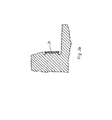
- the 2a is formed by a vertically running surface section provided with a reflective film strip 21 and a surface section running slightly obliquely to the vertical, the latter contributing to a comfortable driving on the threshold 1.
- the surface of the reflective film strip 21 is aligned with the approach of the oblique surface section.
- the reflective film strips 21 are also vulcanized with the individual elements 2, 3 of the threshold 1, so that an optimal adhesion of the same is achieved.
- the rubber-coated reflective film strips 21 are doubled onto a raw rubber plate, which is then cut into strips. These strips are inserted into undercuts of the vulcanizing mold for a single element and vulcanized with the raw rubber of the individual element.
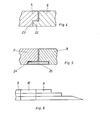
- F ig. 3 shows a single element 4, in which the step-like configuration is delimited on both sides by ramps which end with the step edges. This is one
- Damage to the individual element 4 is prevented when driving over a snow plow.
- Several such individual elements 4 can form a threshold 1.
- FIG. 4 shows a series of individual elements 5, 6, the mutual fit being achieved by mutually identical projections and recesses 22, 23. Another possibility of achieving a mutual fit is shown in FIG. 5, according to which recesses 24 are provided on the underside of the individual elements 7, 8, into which a rod-like guide element 25 is inserted.
- the projections and recesses 22, 23 shown in FIG. 4, like the recess shown in FIG. 5, do not extend over the entire width of the threshold, but only over a partial area, so that alignment is forced.
Landscapes
- Engineering & Computer Science (AREA)
- Architecture (AREA)
- Civil Engineering (AREA)
- Structural Engineering (AREA)
- Road Signs Or Road Markings (AREA)
Applications Claiming Priority (4)
| Application Number | Priority Date | Filing Date | Title |
|---|---|---|---|
| AT1000/83 | 1983-03-22 | ||
| AT0100083A AT378388B (de) | 1983-03-22 | 1983-03-22 | Strassenbauliche einrichtung zur beeinflussung des verkehrs mit kraftfahrzeugen |
| AT270/84 | 1984-01-27 | ||
| AT0027084A AT382659B (de) | 1984-01-27 | 1984-01-27 | Strassenbauliche einrichtung zur beeinflussung des verkehrs mit kraftfahrzeugen und verfahren zur herstellung derselben |
Publications (2)
| Publication Number | Publication Date |
|---|---|
| EP0119986A2 true EP0119986A2 (fr) | 1984-09-26 |
| EP0119986A3 EP0119986A3 (fr) | 1985-12-27 |
Family
ID=25592119
Family Applications (1)
| Application Number | Title | Priority Date | Filing Date |
|---|---|---|---|
| EP84890038A Withdrawn EP0119986A3 (fr) | 1983-03-22 | 1984-03-05 | Dispositif de construction des routes pour influencer le trafic automobile |
Country Status (2)
| Country | Link |
|---|---|
| EP (1) | EP0119986A3 (fr) |
| DK (1) | DK112284A (fr) |
Cited By (3)
| Publication number | Priority date | Publication date | Assignee | Title |
|---|---|---|---|---|
| US5660768A (en) * | 1994-11-09 | 1997-08-26 | Reflexite Corporation | Method for forming a retroreflective structure |
| US5769563A (en) * | 1996-09-26 | 1998-06-23 | Flynn; Gregory | Highway warning device |
| DE10118012A1 (de) * | 2001-04-10 | 2002-10-17 | Maibach Verkehrssicherheit | Plattenförmiges Schwellenelement |
Family Cites Families (6)
| Publication number | Priority date | Publication date | Assignee | Title |
|---|---|---|---|---|
| FR2113800B3 (fr) * | 1970-11-17 | 1973-08-10 | Bourgeon Christian | |
| US3880537A (en) * | 1974-02-05 | 1975-04-29 | Hazard Warning Systems Limited | Road hazard warning device |
| US3980410A (en) * | 1975-06-09 | 1976-09-14 | Itl Industries, Inc. | Pavement marker with snow plow frame |
| GB2030197B (en) * | 1978-04-14 | 1983-03-02 | Ondura Ltd | Portable road surface hump |
| GB2036140A (en) * | 1978-11-14 | 1980-06-25 | Sturtivant G | Road hazard warning device |
| GB2104946B (en) * | 1981-08-11 | 1985-08-07 | Rocol Ltd | Portable road surface ramps |
-
1984
- 1984-02-28 DK DK112284A patent/DK112284A/da not_active Application Discontinuation
- 1984-03-05 EP EP84890038A patent/EP0119986A3/fr not_active Withdrawn
Cited By (3)
| Publication number | Priority date | Publication date | Assignee | Title |
|---|---|---|---|---|
| US5660768A (en) * | 1994-11-09 | 1997-08-26 | Reflexite Corporation | Method for forming a retroreflective structure |
| US5769563A (en) * | 1996-09-26 | 1998-06-23 | Flynn; Gregory | Highway warning device |
| DE10118012A1 (de) * | 2001-04-10 | 2002-10-17 | Maibach Verkehrssicherheit | Plattenförmiges Schwellenelement |
Also Published As
| Publication number | Publication date |
|---|---|
| DK112284A (da) | 1984-09-23 |
| DK112284D0 (da) | 1984-02-28 |
| EP0119986A3 (fr) | 1985-12-27 |
Similar Documents
| Publication | Publication Date | Title |
|---|---|---|
| DE68913168T2 (de) | Strassenmarkierungsband. | |
| CH663809A5 (de) | Sicherheitsueberzug fuer leitplanken. | |
| CH623878A5 (fr) | ||
| DE2546427B1 (de) | Elastischer leitpfosten fuer strassen | |
| DE1534209A1 (de) | Verfahren und Vorrichtung zur Herstellung einer Markierung auf Strassen sowie damit hergestellte Strassenmarkierung | |
| WO1989012142A1 (fr) | Balisage de routes | |
| EP0126982B1 (fr) | Pierre de marquage ayant la forme d'un corps oblong comme une poutre | |
| EP0119986A2 (fr) | Dispositif de construction des routes pour influencer le trafic automobile | |
| DE3334927A1 (de) | Verkehrsleitschwelle | |
| DE19634389C5 (de) | Ortsveränderbare Schiebewand | |
| CH627806A5 (en) | Shaped stone for edge borders and stair steps | |
| DE4433622A1 (de) | Personenförderungsanlage | |
| DE2819006C2 (de) | Warneinrichtung für richtungsgebundene Fahrbahnen zur Verhinderung des Einfahrens in Gegenrichtung | |
| AT378388B (de) | Strassenbauliche einrichtung zur beeinflussung des verkehrs mit kraftfahrzeugen | |
| DE9106411U1 (de) | Trennschwelle für Straßenverkehrsbereiche | |
| AT400864B (de) | Bordstein | |
| DE9004916U1 (de) | Bordstein für Bushaltestellen | |
| DE2636105C3 (de) | Bordstein für Fußgängerüberwege | |
| AT382659B (de) | Strassenbauliche einrichtung zur beeinflussung des verkehrs mit kraftfahrzeugen und verfahren zur herstellung derselben | |
| EP3318674A1 (fr) | Bordure de trottoir et arrêt | |
| DE2903215A1 (de) | Bodenrueckstrahler | |
| EP0875627B1 (fr) | Natte profilée | |
| DE1917931A1 (de) | Abdeckungen fuer Leitplanken an Strassen und Autobahnen | |
| DE69724961T2 (de) | Linien zur abgrenzung von autoabstellflächen | |
| EP1242691B1 (fr) | Dispositif de marquage pour passages pour pietons |
Legal Events
| Date | Code | Title | Description |
|---|---|---|---|
| PUAI | Public reference made under article 153(3) epc to a published international application that has entered the european phase |
Free format text: ORIGINAL CODE: 0009012 |
|
| AK | Designated contracting states |
Designated state(s): AT BE CH DE FR GB IT LI LU NL SE |
|
| PUAL | Search report despatched |
Free format text: ORIGINAL CODE: 0009013 |
|
| AK | Designated contracting states |
Designated state(s): AT BE CH DE FR GB IT LI LU NL SE |
|
| 17P | Request for examination filed |
Effective date: 19860120 |
|
| 17Q | First examination report despatched |
Effective date: 19861212 |
|
| STAA | Information on the status of an ep patent application or granted ep patent |
Free format text: STATUS: THE APPLICATION IS DEEMED TO BE WITHDRAWN |
|
| 18D | Application deemed to be withdrawn |
Effective date: 19870422 |
|
| RIN1 | Information on inventor provided before grant (corrected) |
Inventor name: TICHY, HEINZ Inventor name: HOELLHUBER, EMIL |