EP0120136A1 - Procédé de mesure indirecte d'angles - Google Patents
Procédé de mesure indirecte d'angles Download PDFInfo
- Publication number
- EP0120136A1 EP0120136A1 EP19830112945 EP83112945A EP0120136A1 EP 0120136 A1 EP0120136 A1 EP 0120136A1 EP 19830112945 EP19830112945 EP 19830112945 EP 83112945 A EP83112945 A EP 83112945A EP 0120136 A1 EP0120136 A1 EP 0120136A1
- Authority
- EP
- European Patent Office
- Prior art keywords
- angle
- force
- rope
- measured
- load
- Prior art date
- Legal status (The legal status is an assumption and is not a legal conclusion. Google has not performed a legal analysis and makes no representation as to the accuracy of the status listed.)
- Ceased
Links
- 238000000034 method Methods 0.000 title claims abstract description 13
- 238000005259 measurement Methods 0.000 title claims abstract description 8
- 238000009434 installation Methods 0.000 claims description 8
- 230000010355 oscillation Effects 0.000 claims description 8
- 238000011156 evaluation Methods 0.000 claims description 2
- 230000001629 suppression Effects 0.000 claims 1
- 230000001133 acceleration Effects 0.000 description 2
- 238000004873 anchoring Methods 0.000 description 2
- 230000033001 locomotion Effects 0.000 description 2
- 241000282326 Felis catus Species 0.000 description 1
- 230000003321 amplification Effects 0.000 description 1
- 238000010276 construction Methods 0.000 description 1
- 238000013016 damping Methods 0.000 description 1
- 238000000151 deposition Methods 0.000 description 1
- 238000013461 design Methods 0.000 description 1
- 238000001514 detection method Methods 0.000 description 1
- 238000011161 development Methods 0.000 description 1
- 230000018109 developmental process Effects 0.000 description 1
- 238000010586 diagram Methods 0.000 description 1
- 230000001939 inductive effect Effects 0.000 description 1
- 238000003199 nucleic acid amplification method Methods 0.000 description 1
- 239000000725 suspension Substances 0.000 description 1
- 238000004804 winding Methods 0.000 description 1
Images


Classifications
-
- B—PERFORMING OPERATIONS; TRANSPORTING
- B66—HOISTING; LIFTING; HAULING
- B66C—CRANES; LOAD-ENGAGING ELEMENTS OR DEVICES FOR CRANES, CAPSTANS, WINCHES, OR TACKLES
- B66C13/00—Other constructional features or details
- B66C13/04—Auxiliary devices for controlling movements of suspended loads, or preventing cable slack
- B66C13/06—Auxiliary devices for controlling movements of suspended loads, or preventing cable slack for minimising or preventing longitudinal or transverse swinging of loads
- B66C13/063—Auxiliary devices for controlling movements of suspended loads, or preventing cable slack for minimising or preventing longitudinal or transverse swinging of loads electrical
-
- G—PHYSICS
- G01—MEASURING; TESTING
- G01B—MEASURING LENGTH, THICKNESS OR SIMILAR LINEAR DIMENSIONS; MEASURING ANGLES; MEASURING AREAS; MEASURING IRREGULARITIES OF SURFACES OR CONTOURS
- G01B7/00—Measuring arrangements characterised by the use of electric or magnetic techniques
- G01B7/30—Measuring arrangements characterised by the use of electric or magnetic techniques for measuring angles or tapers; for testing the alignment of axes
Definitions
- the pendulum angle can be recorded directly using mechanical means or by measuring the armature currents of the DC drive motors.
- the use of mechanical devices only leads to a relatively short lifespan due to the high loads in the rough loading area, apart from complicated tracking of the measuring system with some hoist versions (e.g. double link design).
- a similar problem can be found with offshore devices that are above a defined position, e.g. a borehole, positioned with anchors and anchor cables.
- the anchor cables form predetermined angles with respect to the vertical.
- the angles of the anchor cables change with the vertical, so that the offshore device must be returned to the predetermined position via the winch drives. It is also common here to measure the cable angle with mechanically working or inductive sensors.
- the invention has for its object to provide a method that allows the determination of the pendulum angle, the rope exit angle and the like from easily obtained data of the hoist.
- a major advantage of the method according to the invention is that the magnitude and the direction of the respective angle can be inferred from the measurement of two quantities and the drive can thus be acted upon in order to practically prevent a deviation from a predetermined position.
- the fixed roller 1 represents a pure measuring device which is attached to a crane at a suitable point in the course of the cable guide. Since it has no influence on the measurement result in every crane position, that is to say is arranged without weight, a defined force F 1 can be measured on it. The force is exerted by a load F over the rope 3, which is guided over another rope pulley 2.
- the rope 3 comprises the roller 2 depending on the crane position with a changed wrap angle ⁇ .
- the angle ⁇ also changes due to oscillations of the load F, the ge are shown in dashed lines and include the angles g 1 and g 2 with the vertical.
- the mounting position ⁇ of the measuring element for F 2 on the deflection roller 2 with respect to the load rope 3 must, however, be chosen such that, due to the change in the rocking angle ⁇ and thus changing the wrap angle ⁇ , in the extreme positions of the boom, ie in the maximum and minimum Display, equally evaluable measured value differences result. It follows that ⁇ ⁇ becomes 0 °, and there are two further angles such as the angle between the rope 3 and the horizontal and ⁇ as the difference angle between ⁇ and ⁇ .
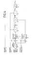
- the circuit according to FIG. 4 supplies the angle sought as a pendulum angle for hoists or the run-out angle for anchored watercraft, which is specified as a control or arithmetic parameter for the corresponding drive controls.
- the input variable for block 15 is the measured luffing angle ⁇ of the boom against the horizontal.
- the function ⁇ ⁇ ( ⁇ ) is simulated in block 15, for example by approximating several straight lines.
- the angle ⁇ is available as the output variable.
- the wrap angle ⁇ is formed at the sum points 16 and the difference angle ⁇ at 17.
- the wrap angle is ⁇ and the installation position of angle ⁇ , from which a trigenometrischer factor is formed, which, multiplied by the tensile force F 1 in block 20, for determining the desired force F to, is based on the installation position, used:
- the comparison point 21 forms the difference ⁇ F from the target force Fset and the measured actual force F 2 .
- This difference value can be both positive and negative.
- the tangent of the pendulum angle g is the ratio of the horizontal component F HOR to the measured load F 1 , block 23; from which the angle g in size and direction results from block 24
- the method just described can also be used to determine the angles which the anchored ropes assume with the perpendicular in anchored vehicles such as offshore devices. From the deviation of these angles from a predetermined value, a change in position of the vehicle can be concluded. Likewise, if the sea depth is known, the position of the anchor relative to the device can be determined using the rope outlet angle determined by the method. This knowledge is important for anchoring ropes on moving units, such as pipe-laying machines, in order to avoid the need to initiate sales Predetermine agile rope forces.
- FIG. 2 shows a vehicle 5 with an anchor winch 7 driven by a motor 6, from which an anchor cable 8 runs via a measuring roller 9 and a deflection roller 10 to an anchor 11 lying on the seabed.
- the vehicle has a plurality of such anchoring systems.
- the target position of the vehicle is reached when the anchor cables run in the direction drawn to the anchor, i.e. the target outlet angle is maintained. If, on the other hand, the vehicle is outside the target position, the run-out angle and the direction of the rope to the anchor change (dashed lines in FIG. 2).
- the amount and the direction of the run-out angle, which exists between the target direction and the currently assumed direction of the anchor rope, can be determined according to the above equations and the winch drives can be operated accordingly.
Landscapes
- Physics & Mathematics (AREA)
- General Physics & Mathematics (AREA)
- Engineering & Computer Science (AREA)
- Mechanical Engineering (AREA)
- Jib Cranes (AREA)
- Control And Safety Of Cranes (AREA)
- Spectrometry And Color Measurement (AREA)
- Eye Examination Apparatus (AREA)
- Paper (AREA)
Applications Claiming Priority (2)
| Application Number | Priority Date | Filing Date | Title |
|---|---|---|---|
| DE19833302458 DE3302458A1 (de) | 1983-01-26 | 1983-01-26 | Verfahren zur indirekten messung von winkeln |
| DE3302458 | 1983-01-26 |
Publications (1)
| Publication Number | Publication Date |
|---|---|
| EP0120136A1 true EP0120136A1 (fr) | 1984-10-03 |
Family
ID=6189201
Family Applications (1)
| Application Number | Title | Priority Date | Filing Date |
|---|---|---|---|
| EP19830112945 Ceased EP0120136A1 (fr) | 1983-01-26 | 1983-12-22 | Procédé de mesure indirecte d'angles |
Country Status (3)
| Country | Link |
|---|---|
| EP (1) | EP0120136A1 (fr) |
| DE (1) | DE3302458A1 (fr) |
| NO (1) | NO840126L (fr) |
Cited By (3)
| Publication number | Priority date | Publication date | Assignee | Title |
|---|---|---|---|---|
| EP0583816A1 (fr) * | 1992-08-04 | 1994-02-23 | FINMECCANICA S.p.A. AZIENDA ANSALDO | Procédé pour déterminer l'angle de l'inclinaison d'un câble, et un appareil pour prevenir des oscillations pendulaires par réglage de cet angle dans un appareil élévateur |
| EP2538189A1 (fr) * | 2011-06-22 | 2012-12-26 | Brosa AG | Douille de mesure de force et procédé de calcul de force |
| CN117190951A (zh) * | 2023-11-08 | 2023-12-08 | 国网湖北省电力有限公司中超建设管理公司 | 一种特高压线缆长度高精度测量装置 |
Families Citing this family (2)
| Publication number | Priority date | Publication date | Assignee | Title |
|---|---|---|---|---|
| US5392935A (en) * | 1992-10-06 | 1995-02-28 | Obayashi Corporation | Control system for cable crane |
| CN110940257B (zh) * | 2018-09-25 | 2021-09-24 | 国核电站运行服务技术有限公司 | 一种测量管道倾角变化的装置及方法 |
Citations (7)
| Publication number | Priority date | Publication date | Assignee | Title |
|---|---|---|---|---|
| DE1139257B (de) * | 1960-03-19 | 1962-11-08 | Wilhelm Reich Maschinenfabrik | Vorrichtung zur selbsttaetigen Begrenzung des Lastmomentes bei Kranen |
| DE1228770B (de) * | 1964-04-04 | 1966-11-17 | Karl Peschke Baumaschinenfabri | UEberlastsicherung an Turmdrehkraenen mit Laufkatzenausleger |
| DE1950885A1 (de) * | 1969-10-09 | 1971-04-22 | Demag Ag | Vorrichtung zum Daempfen von Lastpendelbewegungen an Doppellenker-Wippkranen |
| DE1278079B (de) * | 1964-10-26 | 1975-01-09 | Licentia Patent-Verwaltungs G m b H , 6000 Frankfurt | Anordnung zur selbsttätigen Unterdrückung der Pendelungen einer an einem Seil hangenden Last, insbesondere eines an einer Laufkatze hangenden Greifers einer Verladebrücke |
| GB1474751A (en) * | 1975-07-23 | 1977-05-25 | Ferranti Ltd | Angle measurement |
| FR2401407A1 (fr) * | 1977-06-16 | 1979-03-23 | Preux Roger | Procede et systeme de calcul de la charge d'un engin de levage ramenee au crochet d'une grue |
| GB1590300A (en) * | 1976-12-27 | 1981-05-28 | Santa Fe Int Corp | Sea sled tow line vector system |
-
1983
- 1983-01-26 DE DE19833302458 patent/DE3302458A1/de not_active Withdrawn
- 1983-12-22 EP EP19830112945 patent/EP0120136A1/fr not_active Ceased
-
1984
- 1984-01-13 NO NO840126A patent/NO840126L/no unknown
Patent Citations (7)
| Publication number | Priority date | Publication date | Assignee | Title |
|---|---|---|---|---|
| DE1139257B (de) * | 1960-03-19 | 1962-11-08 | Wilhelm Reich Maschinenfabrik | Vorrichtung zur selbsttaetigen Begrenzung des Lastmomentes bei Kranen |
| DE1228770B (de) * | 1964-04-04 | 1966-11-17 | Karl Peschke Baumaschinenfabri | UEberlastsicherung an Turmdrehkraenen mit Laufkatzenausleger |
| DE1278079B (de) * | 1964-10-26 | 1975-01-09 | Licentia Patent-Verwaltungs G m b H , 6000 Frankfurt | Anordnung zur selbsttätigen Unterdrückung der Pendelungen einer an einem Seil hangenden Last, insbesondere eines an einer Laufkatze hangenden Greifers einer Verladebrücke |
| DE1950885A1 (de) * | 1969-10-09 | 1971-04-22 | Demag Ag | Vorrichtung zum Daempfen von Lastpendelbewegungen an Doppellenker-Wippkranen |
| GB1474751A (en) * | 1975-07-23 | 1977-05-25 | Ferranti Ltd | Angle measurement |
| GB1590300A (en) * | 1976-12-27 | 1981-05-28 | Santa Fe Int Corp | Sea sled tow line vector system |
| FR2401407A1 (fr) * | 1977-06-16 | 1979-03-23 | Preux Roger | Procede et systeme de calcul de la charge d'un engin de levage ramenee au crochet d'une grue |
Cited By (4)
| Publication number | Priority date | Publication date | Assignee | Title |
|---|---|---|---|---|
| EP0583816A1 (fr) * | 1992-08-04 | 1994-02-23 | FINMECCANICA S.p.A. AZIENDA ANSALDO | Procédé pour déterminer l'angle de l'inclinaison d'un câble, et un appareil pour prevenir des oscillations pendulaires par réglage de cet angle dans un appareil élévateur |
| EP2538189A1 (fr) * | 2011-06-22 | 2012-12-26 | Brosa AG | Douille de mesure de force et procédé de calcul de force |
| CN117190951A (zh) * | 2023-11-08 | 2023-12-08 | 国网湖北省电力有限公司中超建设管理公司 | 一种特高压线缆长度高精度测量装置 |
| CN117190951B (zh) * | 2023-11-08 | 2024-01-23 | 国网湖北省电力有限公司中超建设管理公司 | 一种特高压线缆长度高精度测量装置 |
Also Published As
| Publication number | Publication date |
|---|---|
| NO840126L (no) | 1984-07-27 |
| DE3302458A1 (de) | 1984-07-26 |
Similar Documents
| Publication | Publication Date | Title |
|---|---|---|
| DE69518566T2 (de) | Verfahren zum führerlosen Betrieb eines Krans und Apparat dazu | |
| EP2614027B1 (fr) | Procédé de commande d'une machine d'entraînement d'un système d'ascenseur | |
| EP2298687B1 (fr) | Système de détection de la masse de charge d'une charge suspendue à une corde de levage de grue | |
| DE60006040T2 (de) | Dünungskompensationsvorrichtung | |
| DE3911391C5 (de) | Verfahren und Vorrichtung zum Überprüfen der Treibfähigkeit | |
| DE793615T1 (de) | Verfahren und vorrichtung zum steueren des lasttragelementes und last von einem kran | |
| WO2004031065A2 (fr) | Procede et dispositif de positionnement d'une charge | |
| EP1390286B1 (fr) | Systeme et procede pour mesurer la deviation horizontale d'un support de charge | |
| EP2878566B1 (fr) | Procédé d'influence d'un mouvement d'une charge logée au niveau d'une grue | |
| EP3409636A1 (fr) | Procédé permettant d'amortir des vibrations de torsion d'un élément de réception de charge d'un dispositif de levage | |
| DE849207T1 (de) | Verfahren und Vorrichtung zur Messung der Last einer Aufzugskabine | |
| JPH036287B2 (fr) | ||
| EP0563836A2 (fr) | Méthode pour mesurer la capacité d'entraînement d'un installation de transport | |
| WO2021037530A1 (fr) | Unité de commande et procédé d'actionnement d'un moyen de transport | |
| EP0120136A1 (fr) | Procédé de mesure indirecte d'angles | |
| DE112019006753T5 (de) | Aufzugsvorrichtung | |
| DE69432653T2 (de) | Kontroll- und Steuersystem für die Geschwindigkeit einer bewegten, pendelnden Ladung und Hebevorrichtung mit einem solchen System | |
| DE112012002180B4 (de) | Aufzuganlage | |
| DE102020205218A1 (de) | Verfahren und System zur Bestimmung des Seilschlupfes einer seilgebundenen Aufzugsanlage | |
| DE3335402C2 (fr) | ||
| EP1834920B1 (fr) | Procédé pour la manipulation automatique d'une charge de grue avec amortissement d'oscillations pendulaires et commande de parcours | |
| DE3710492C2 (fr) | ||
| DE1278079C2 (de) | Anordnung zur selbsttaetigen unterdrueckung der pendelungen einer an einem seil haengenden last, insbesondere eines an einer laufkatze haengenden greifers einer verladebruecke | |
| DE102018123150A1 (de) | Drehgeber und Verfahren zum Betrieb eines Hebezeugs | |
| DE19826695A1 (de) | Verfahren und Vorrichtung zur Ausregelung eines Verdrehwinkels einer Last |
Legal Events
| Date | Code | Title | Description |
|---|---|---|---|
| PUAI | Public reference made under article 153(3) epc to a published international application that has entered the european phase |
Free format text: ORIGINAL CODE: 0009012 |
|
| AK | Designated contracting states |
Designated state(s): BE IT NL SE |
|
| 17P | Request for examination filed |
Effective date: 19850313 |
|
| 17Q | First examination report despatched |
Effective date: 19860526 |
|
| STAA | Information on the status of an ep patent application or granted ep patent |
Free format text: STATUS: THE APPLICATION HAS BEEN REFUSED |
|
| 18R | Application refused |
Effective date: 19870803 |
|
| RIN1 | Information on inventor provided before grant (corrected) |
Inventor name: WOICKE, GUENTER, ING.GRAD. |