EP0120152A1 - Appareil pour minimiser les pertes de fluide d'une partie composante d'un système hydraulique en cas de panne de la partie composante - Google Patents
Appareil pour minimiser les pertes de fluide d'une partie composante d'un système hydraulique en cas de panne de la partie composante Download PDFInfo
- Publication number
- EP0120152A1 EP0120152A1 EP83301481A EP83301481A EP0120152A1 EP 0120152 A1 EP0120152 A1 EP 0120152A1 EP 83301481 A EP83301481 A EP 83301481A EP 83301481 A EP83301481 A EP 83301481A EP 0120152 A1 EP0120152 A1 EP 0120152A1
- Authority
- EP
- European Patent Office
- Prior art keywords
- chamber
- fluid
- component
- tank
- level
- Prior art date
- Legal status (The legal status is an assumption and is not a legal conclusion. Google has not performed a legal analysis and makes no representation as to the accuracy of the status listed.)
- Granted
Links
- 239000012530 fluid Substances 0.000 title claims abstract description 64
- 238000012423 maintenance Methods 0.000 description 1
- 230000008439 repair process Effects 0.000 description 1
- 239000011435 rock Substances 0.000 description 1
- 230000000007 visual effect Effects 0.000 description 1
Images
Classifications
-
- F—MECHANICAL ENGINEERING; LIGHTING; HEATING; WEAPONS; BLASTING
- F15—FLUID-PRESSURE ACTUATORS; HYDRAULICS OR PNEUMATICS IN GENERAL
- F15B—SYSTEMS ACTING BY MEANS OF FLUIDS IN GENERAL; FLUID-PRESSURE ACTUATORS, e.g. SERVOMOTORS; DETAILS OF FLUID-PRESSURE SYSTEMS, NOT OTHERWISE PROVIDED FOR
- F15B1/00—Installations or systems with accumulators; Supply reservoir or sump assemblies
- F15B1/26—Supply reservoir or sump assemblies
-
- F—MECHANICAL ENGINEERING; LIGHTING; HEATING; WEAPONS; BLASTING
- F02—COMBUSTION ENGINES; HOT-GAS OR COMBUSTION-PRODUCT ENGINE PLANTS
- F02B—INTERNAL-COMBUSTION PISTON ENGINES; COMBUSTION ENGINES IN GENERAL
- F02B1/00—Engines characterised by fuel-air mixture compression
- F02B1/02—Engines characterised by fuel-air mixture compression with positive ignition
- F02B1/04—Engines characterised by fuel-air mixture compression with positive ignition with fuel-air mixture admission into cylinder
Definitions
- This invention relates to an apparatus for minimising the amount of fluid leaked from a component in a. hydraulic power system when the component has failed such as for example a hose-burst.
- Hand-held hydraulic tools such as roadbreakers and rock drills are supplied with the hydraulic operating fluid by way of hoses which are connected via a power source prime mover such as a diesel or petrol engine to a tank serving as a reservoir for the fluid.
- hoses are subject to severe wear and tear during use and as a result frequently split or crack. Since the hydraulic fluid continuously circulates through these hoses at pressures of at least 200 psi even when the tools are not being operated ie during standby or rest periods, fluid leaks at high velocity through such fissures in the hose wall. This may lead to a quite substantial loss of the expensive operating fluid and will create an unacceptable hazard to the site operatives and the environment.
- the leakage can be kept to tolerably acceptable levels should an operative notice the leak quickly enough and deactivate the prime mover. However, in most cases, and particularly where the hoses are long, the operative may not notice the leak until significant fluid loss has occurred.
- apparatus for minimising the amount of fluid leaked from,a component in a hydraulic power system when the component has failed, the apparatus comprising a tank for use as the reservoir for the hydraulic fluid, the tank having a first chamber for storing a main volume of the fluid and a second chamber communicating with the first chamber for storing a reference volume of the fluid above the main volume and means for deactivating the system power source when the quantity of fluid in the second chamber has fallen to or below a preset level as a result of its leakage from the system, the chambers being so dimensioned that for a given quantity of fluid entering or leaving the tank, fluid level fluctuation in the second chamber is greater than the corresponding fluid level fluctuation which would occur in the first chamber if the fluid were only entering or leaving the first chamber.
- the means for deactivating the power source comprises a fluid level switch located in the second chamber.
- the tank includes an expansion chamber communicating with the second chamber.
- a hydraulic power system includes the apparatus defined above.
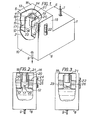
- the apparatus comprises a tank 1 providing a reservoir for a hydraulic fluid which is to serve as the working fluid in a conventional hydraulic power system incorporating hoses and other like components and a power source such as a diesel or petrol engine.
- the tank 1 comprises a lowermost chamber 2 for storing a main or major volume of the fluid, an upper chamber 3 for storing a reference minor volume of the fluid and an upper chamber 4 communicating with the chamber 3 serving as an expansion chamber.
- the upper chambers 3 and 4 are housed in an extension 5 to the lowermost chamber 2.
- the top wall 6 of the lowermost chamber 2 is provided with an inlet 7 for fluid returning from the system after use while the lower wall 8 of the chamber 2 is provided with an outlet 9 to supply fluid to the system for use.
- the upper chamber 3 is formed between the front wall 10 of the tank 1 and an open-ended vertical channel component 11 which is welded to the wall 10.
- the expansion chamber 4 is formed within the extension 5 by means of a flange 12 extending from the base of the channel component 11 and welded to the adjacent walls 10,13,14 and 15 of the tank 1.
- the channel component 11 terminates short of the top wall 16 of the extension 5 and a series of drain holes 17 is provided in each of the walls 18, 19 and 20 of the component 11 close to the base thereof.
- the holes 17 provide access for fluid to enter the expansion chamber 4 from the chamber 3 or leave the expansion chamber 4 to enter the chamber 3.
- a. conventional oil filter element 21 for an oil filter or breather, the element 21 extending into the chamber 3 formed by the channel component 11.
- a conventional fluid level gauge 22 mounted on the wall 15 of the tank 1 is a conventional fluid level gauge 22 to provide a visual indication of the fluid level in the expansion chamber 4.
- a conventional fluid level limit switch 23 shown in schematic form).
- This switch 23 is electrically connected by means (not shown) to the power source for example, a petrol or diesel engine, so that when the fluid in the chamber 3 falls to the level of the switch 23, the switch 23 switches off the power source to cause circulation of the fluid within the system to cease.
- the power source for example, a petrol or diesel engine
- the fluid 24 fills the lowermost chamber 2 and forms a column 25 in the chamber 3, above the level of the switch 23.
- the level 26 of fluid in the chamber 3 remains substantially constant if operation is normal but in any case the fluid column 25 forms a fluid reference volume and because of the relative dimensions of the chambers 2 and 3, fluid level fluctuations in the reference chamber 3 are much greater than those in the lower chamber 2 if the same volume of fluid were entering or leaving only the lower chamber. Hence a small quantity of fluid lost from the main chamber 2 will result in a rapid and considerable change in fluid level in the reference volume.
- the volume of the fluid leaked from the tank 1 during failure of a component can be limited to an extremely low level.
- a manual override should be fitted to the fluid level switch to prevent the power source being cut out while topping up the fluid reservoir after maintenance or repairs.
- the apparatus substantially eleiminates the problem of fluid expansion through the temperature range associated with outdoor work.
Landscapes
- Engineering & Computer Science (AREA)
- Physics & Mathematics (AREA)
- Fluid Mechanics (AREA)
- Mechanical Engineering (AREA)
- General Engineering & Computer Science (AREA)
- Supply Devices, Intensifiers, Converters, And Telemotors (AREA)
Priority Applications (2)
| Application Number | Priority Date | Filing Date | Title |
|---|---|---|---|
| DE8383301481T DE3372118D1 (en) | 1983-03-17 | 1983-03-17 | Apparatus for minimising the amount of fluid leaked from a component in a hydraulic system when the component has failed |
| EP19830301481 EP0120152B1 (fr) | 1983-03-17 | 1983-03-17 | Appareil pour minimiser les pertes de fluide d'une partie composante d'un système hydraulique en cas de panne de la partie composante |
Applications Claiming Priority (1)
| Application Number | Priority Date | Filing Date | Title |
|---|---|---|---|
| EP19830301481 EP0120152B1 (fr) | 1983-03-17 | 1983-03-17 | Appareil pour minimiser les pertes de fluide d'une partie composante d'un système hydraulique en cas de panne de la partie composante |
Publications (2)
| Publication Number | Publication Date |
|---|---|
| EP0120152A1 true EP0120152A1 (fr) | 1984-10-03 |
| EP0120152B1 EP0120152B1 (fr) | 1987-06-16 |
Family
ID=8191090
Family Applications (1)
| Application Number | Title | Priority Date | Filing Date |
|---|---|---|---|
| EP19830301481 Expired EP0120152B1 (fr) | 1983-03-17 | 1983-03-17 | Appareil pour minimiser les pertes de fluide d'une partie composante d'un système hydraulique en cas de panne de la partie composante |
Country Status (2)
| Country | Link |
|---|---|
| EP (1) | EP0120152B1 (fr) |
| DE (1) | DE3372118D1 (fr) |
Citations (5)
| Publication number | Priority date | Publication date | Assignee | Title |
|---|---|---|---|---|
| FR577250A (fr) * | 1924-02-16 | 1924-09-02 | Appareil pour indiquer le niveau du liquide contenu dans un réservoir et avertir quand ce niveau descend au-dessous d'une certaine limite | |
| FR919822A (fr) * | 1946-01-07 | 1947-03-19 | Automobiles De Dion Bouton | Dispositif protecteur d'un moteur thermique ou de toute autre machine contre le manque d'eau de refroidissement |
| FR1435198A (fr) * | 1965-03-06 | 1966-04-15 | Garnier & Cie A | Procédé et dispositif pour la protection des moteurs thermiques à refroidissementpar liquide |
| US3832982A (en) * | 1973-09-10 | 1974-09-03 | H Guehr | Coolant loss or coolant pump malfunction detection system for internal combustion engines |
| DE2715569A1 (de) * | 1977-04-07 | 1978-10-12 | Volkswagenwerk Ag | Vorrichtung zum abschalten einer hydraulikanlage |
-
1983
- 1983-03-17 DE DE8383301481T patent/DE3372118D1/de not_active Expired
- 1983-03-17 EP EP19830301481 patent/EP0120152B1/fr not_active Expired
Patent Citations (5)
| Publication number | Priority date | Publication date | Assignee | Title |
|---|---|---|---|---|
| FR577250A (fr) * | 1924-02-16 | 1924-09-02 | Appareil pour indiquer le niveau du liquide contenu dans un réservoir et avertir quand ce niveau descend au-dessous d'une certaine limite | |
| FR919822A (fr) * | 1946-01-07 | 1947-03-19 | Automobiles De Dion Bouton | Dispositif protecteur d'un moteur thermique ou de toute autre machine contre le manque d'eau de refroidissement |
| FR1435198A (fr) * | 1965-03-06 | 1966-04-15 | Garnier & Cie A | Procédé et dispositif pour la protection des moteurs thermiques à refroidissementpar liquide |
| US3832982A (en) * | 1973-09-10 | 1974-09-03 | H Guehr | Coolant loss or coolant pump malfunction detection system for internal combustion engines |
| DE2715569A1 (de) * | 1977-04-07 | 1978-10-12 | Volkswagenwerk Ag | Vorrichtung zum abschalten einer hydraulikanlage |
Also Published As
| Publication number | Publication date |
|---|---|
| DE3372118D1 (en) | 1987-07-23 |
| EP0120152B1 (fr) | 1987-06-16 |
Similar Documents
| Publication | Publication Date | Title |
|---|---|---|
| US5846056A (en) | Reciprocating pump system and method for operating same | |
| US4513774A (en) | Apparatus for minimizing the amount of fluid leaked from a component in a hydraulic power system when the system has failed | |
| US4089621A (en) | Selectively pressurized tank for hydraulic fluid | |
| US4019680A (en) | Steam generating system including means for reinitiating the operation of a steam bound boiler feed pump | |
| EP0426758B1 (fr) | Systeme de lubrification pour moteurs | |
| US4576197A (en) | Pump suction vacuum lift vortex control | |
| KR102077810B1 (ko) | 연료분사밸브 시험 장치 및 시험 방법 | |
| NO123115B (fr) | ||
| US2102140A (en) | System and apparatus for pumping hazardous liquids | |
| US3503618A (en) | Arrangement for ensuring supply of pressurized sealing fluid to shaft seals of high pressure machines to prevent gas leakage in event of failure of main oil pump | |
| EP0120152A1 (fr) | Appareil pour minimiser les pertes de fluide d'une partie composante d'un système hydraulique en cas de panne de la partie composante | |
| US6053702A (en) | Portable water pump having a pressure control circuit with a bypass conduit | |
| GB2115071A (en) | Apparatus for minimising the amount of fluid leaked from a component in a hydraulic power system when the component has failed | |
| US4589524A (en) | Overfill valve | |
| US2214816A (en) | Power transmission | |
| US6086331A (en) | Safety pumping system for hazardous environments using pressurized gas in a plurality of chambers | |
| US4564084A (en) | Method and apparatus for controlling the temperature of oil in an overhead tank | |
| CA1188959A (fr) | Dispositif pour reduire l'ampleur des fuites de fluide a l'endroit d'un organe de reseau de commande hydraulique advenant la defaillance dudit organe | |
| KR100551941B1 (ko) | 무정전 상태에서의 변압기 절연유 절연보강장치 | |
| US4784089A (en) | Cooling system for a water-cooled internal combustion engine | |
| EP1261803B1 (fr) | Appareil de retour de fuite d'huile pour moteur hydraulique | |
| US5156109A (en) | System to reduce spillage of oil due to rupture of ship's tank | |
| EP1436511B1 (fr) | Procede pour reduire les fuites d'huile hydraulique d'un appareil de forage de roche | |
| US3406895A (en) | Apparatus for the uttlization of combustible waste gases of refineries or other plants | |
| JP2822548B2 (ja) | タレット式工作機械の潤滑油循環方法 |
Legal Events
| Date | Code | Title | Description |
|---|---|---|---|
| PUAI | Public reference made under article 153(3) epc to a published international application that has entered the european phase |
Free format text: ORIGINAL CODE: 0009012 |
|
| AK | Designated contracting states |
Designated state(s): BE DE FR IT NL SE |
|
| 17P | Request for examination filed |
Effective date: 19841016 |
|
| GRAA | (expected) grant |
Free format text: ORIGINAL CODE: 0009210 |
|
| AK | Designated contracting states |
Kind code of ref document: B1 Designated state(s): BE DE FR IT NL SE |
|
| REF | Corresponds to: |
Ref document number: 3372118 Country of ref document: DE Date of ref document: 19870723 |
|
| ITF | It: translation for a ep patent filed | ||
| ET | Fr: translation filed | ||
| BECH | Be: change of holder |
Free format text: 870616 *BRITISH GAS P.L.C. |
|
| NLS | Nl: assignments of ep-patents |
Owner name: BRITISH GAS PLC TE LONDEN, GROOT-BRITTANNIE. |
|
| PLBE | No opposition filed within time limit |
Free format text: ORIGINAL CODE: 0009261 |
|
| STAA | Information on the status of an ep patent application or granted ep patent |
Free format text: STATUS: NO OPPOSITION FILED WITHIN TIME LIMIT |
|
| 26N | No opposition filed | ||
| REG | Reference to a national code |
Ref country code: FR Ref legal event code: TP |
|
| PGFP | Annual fee paid to national office [announced via postgrant information from national office to epo] |
Ref country code: FR Payment date: 19920210 Year of fee payment: 10 |
|
| PGFP | Annual fee paid to national office [announced via postgrant information from national office to epo] |
Ref country code: SE Payment date: 19920217 Year of fee payment: 10 |
|
| PGFP | Annual fee paid to national office [announced via postgrant information from national office to epo] |
Ref country code: DE Payment date: 19920219 Year of fee payment: 10 Ref country code: BE Payment date: 19920219 Year of fee payment: 10 |
|
| ITTA | It: last paid annual fee | ||
| PGFP | Annual fee paid to national office [announced via postgrant information from national office to epo] |
Ref country code: NL Payment date: 19920331 Year of fee payment: 10 |
|
| PG25 | Lapsed in a contracting state [announced via postgrant information from national office to epo] |
Ref country code: SE Effective date: 19930318 |
|
| PG25 | Lapsed in a contracting state [announced via postgrant information from national office to epo] |
Ref country code: BE Effective date: 19930331 |
|
| BERE | Be: lapsed |
Owner name: BRITISH GAS P.L.C. Effective date: 19930331 |
|
| PG25 | Lapsed in a contracting state [announced via postgrant information from national office to epo] |
Ref country code: NL Effective date: 19931001 |
|
| NLV4 | Nl: lapsed or anulled due to non-payment of the annual fee | ||
| PG25 | Lapsed in a contracting state [announced via postgrant information from national office to epo] |
Ref country code: FR Effective date: 19931130 |
|
| PG25 | Lapsed in a contracting state [announced via postgrant information from national office to epo] |
Ref country code: DE Effective date: 19931201 |
|
| REG | Reference to a national code |
Ref country code: FR Ref legal event code: ST |
|
| EUG | Se: european patent has lapsed |
Ref document number: 83301481.4 Effective date: 19931008 |