EP0120173B1 - Diffusor für Gasturbinentriebwerk - Google Patents
Diffusor für Gasturbinentriebwerk Download PDFInfo
- Publication number
- EP0120173B1 EP0120173B1 EP83630187A EP83630187A EP0120173B1 EP 0120173 B1 EP0120173 B1 EP 0120173B1 EP 83630187 A EP83630187 A EP 83630187A EP 83630187 A EP83630187 A EP 83630187A EP 0120173 B1 EP0120173 B1 EP 0120173B1
- Authority
- EP
- European Patent Office
- Prior art keywords
- air
- burner
- diffuser
- prediffuser
- leading
- Prior art date
- Legal status (The legal status is an assumption and is not a legal conclusion. Google has not performed a legal analysis and makes no representation as to the accuracy of the status listed.)
- Expired
Links
- 238000002485 combustion reaction Methods 0.000 claims description 22
- 238000010790 dilution Methods 0.000 claims description 14
- 239000012895 dilution Substances 0.000 claims description 14
- 238000007599 discharging Methods 0.000 claims description 6
- 239000000446 fuel Substances 0.000 claims description 6
- 238000005452 bending Methods 0.000 claims description 4
- 230000007704 transition Effects 0.000 claims description 3
- 238000001816 cooling Methods 0.000 description 12
- 238000006243 chemical reaction Methods 0.000 description 1
- 238000010276 construction Methods 0.000 description 1
- 238000009434 installation Methods 0.000 description 1
- 238000000034 method Methods 0.000 description 1
- 230000003068 static effect Effects 0.000 description 1
- 238000009966 trimming Methods 0.000 description 1
Images

Classifications
-
- F—MECHANICAL ENGINEERING; LIGHTING; HEATING; WEAPONS; BLASTING
- F02—COMBUSTION ENGINES; HOT-GAS OR COMBUSTION-PRODUCT ENGINE PLANTS
- F02C—GAS-TURBINE PLANTS; AIR INTAKES FOR JET-PROPULSION PLANTS; CONTROLLING FUEL SUPPLY IN AIR-BREATHING JET-PROPULSION PLANTS
- F02C7/00—Features, components parts, details or accessories, not provided for in, or of interest apart form groups F02C1/00 - F02C6/00; Air intakes for jet-propulsion plants
- F02C7/12—Cooling of plants
- F02C7/16—Cooling of plants characterised by cooling medium
- F02C7/18—Cooling of plants characterised by cooling medium the medium being gaseous, e.g. air
-
- F—MECHANICAL ENGINEERING; LIGHTING; HEATING; WEAPONS; BLASTING
- F23—COMBUSTION APPARATUS; COMBUSTION PROCESSES
- F23R—GENERATING COMBUSTION PRODUCTS OF HIGH PRESSURE OR HIGH VELOCITY, e.g. GAS-TURBINE COMBUSTION CHAMBERS
- F23R3/00—Continuous combustion chambers using liquid or gaseous fuel
- F23R3/02—Continuous combustion chambers using liquid or gaseous fuel characterised by the air-flow or gas-flow configuration
-
- Y—GENERAL TAGGING OF NEW TECHNOLOGICAL DEVELOPMENTS; GENERAL TAGGING OF CROSS-SECTIONAL TECHNOLOGIES SPANNING OVER SEVERAL SECTIONS OF THE IPC; TECHNICAL SUBJECTS COVERED BY FORMER USPC CROSS-REFERENCE ART COLLECTIONS [XRACs] AND DIGESTS
- Y02—TECHNOLOGIES OR APPLICATIONS FOR MITIGATION OR ADAPTATION AGAINST CLIMATE CHANGE
- Y02T—CLIMATE CHANGE MITIGATION TECHNOLOGIES RELATED TO TRANSPORTATION
- Y02T50/00—Aeronautics or air transport
- Y02T50/60—Efficient propulsion technologies, e.g. for aircraft
Definitions
- This invention relates to a diffuser and burner assembly in a gas turbine engine, comprising an annularly shaped prediffuser, a dump cavity surrounding the burner and forming a passageway for leading airto the turbine section of the gas turbine engine, means for dumping air from the pre-diffuser into the dump cavity, means for leading a primary flow of combustion air into the burner through the front end thereof, and means for leading a secondary flow of combustion and dilution air into the burner.
- a diffuser and burner assembly of this type is known from US-A-3 826 084 and GB-A-741 488, each having a prediffuser and dump diffuser disposed downstream of the compressor feeding compressor discharge air to the burner.
- compressor air is discharged into the prediffuser which serves to convert a portion of the dynamic pressure head to static pressure whereupon it is then dumped into the dump diffuser for additional conversion, but with high pressure losses.
- a portion of the now slower moving air is admitted internally of the burner liner to the combustion zones while an additional portion is utilized to cool the liner itself.
- An object of the invention is to provide an improved diffuser and burner assembly for a gas turbine engine having reduced pressure losses.
- the diffuser and burner assembly is characterized in that the means for dumping air from the prediffuser into the dump cavity comprises at least one pipe supported adjacent the discharge end of the prediffuser and having a forward open end spaced from the walls of the prediffuser for capturing the air discharging with the highest total pressure and a rear open end dumping the captured air into the dump cavity, and that means for leading the primary and secondary airflows into the burner comprises a transition pipe section for collecting the prediffuser discharge air not being captured by said at least one pipe and a tubular connecting section interconnected with said burner for feeding the combustion and dilution air directly into the burner.
- the pressure losses are reduced by discharging the air from the prediffuser into two streams.
- One stream ducts the air with reduced losses to and around the burner to supply liner cooling air, turbine cooling air and if necessary, small amounts of dilution air to trim the radial temperature profile.
- the other stream is ducted without the usual dump loss directly into the front end of the burner and supplies the combustion and dilution air.
- This latter stream without its usual large dump loss and its low loss front feed, has the ability to absorb substantial loss penalties and still provide for a low overall burner pressure loss. This capability is utilized to minimize the pressure losses in the heretofore utilized cooling air circuit.
- the compressor discharge air leaving the diffuser for feeding the burner shrouds for liner and turbine cooling is captured from the center of the gas path where the total pressure is highest.
- the ducts that capture this air may have expanding cross-sectional areas and commence with zero boundary layer at their walls, and thus may function as an additional diffuser stage, further reducing the dynamic pressure head and discharging this cooling air into the burner shroud region with a substantially reduced dump loss.
- the remaining air not intercepted by the capturing ducts, (the center region air and all the boundary layer air adjacentto the walls of the prediffuser) is collected by a number of transition sections into discrete pipes where the air is delivered to and into the front end of the burner as combustion and dilution air without the usual diffuser dump loss. Tests that have been conducted have shown that this front- feed combustion and dilution air concept has proven itself to be a low loss burner system.
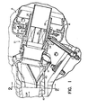
- the air discharging from the compressor is fed into the diffuser generally indicated by reference numeral 10 which is annular in shape where the air is efficiently diffused and separated into basically two streams.
- one stream consists of capturing the air at the center of the diffuser for feeding cooling air for burner liner and turbine cooling and the other stream captures the remaining portion for feeding combustion and dilution air to the burner.
- a plurality of pipes are discretely mounted about the circumference of the diffuser to achieve the proper air feeding and distribution pattern necessary for a given engine design.
- compressor discharge air in the diffuser 10 at the discharge end is captured by pipes 12 and 14 one bending in an upward direction and the other bending in a downward direction, each pipe having an expanding cross section to provide a second diffuser stage before dumping air in the cavity surrounding the burner liners generally indicated by reference numerals 16 and 18.
- Both pipes 12 and 14 are configured so that at the bend and in close proximity thereto the cross-sectional area stays constant. Downstream of the bend the inner diameter begins to increase flaring to a larger cross-sectional area at the discharge end forming a cone portion which defines the second diffuser stage.
- the burner liner comprises a plurality of louver sections joined together to form an inner and outer wall for defining an annular burning section which surrounds the engine shaft (not shown). This defines an annular combustor which is closed on the front end by the dome member 20.
- a plurality of fuel/air admission modules 21 (one being shown) is mounted in apertures formed on the front end of the dome. The fuel/air admission module is supported to the dome by the upstanding heat shield member 22 which is clamped by clamp 24 to the arm of the U-shaped dome member 20.
- This module which comprises a pair of concentric tubes 26 and 28 for defining the secondary airflow which serves as the combustion and dilution air. Suitable vanes may be employed to impart a swirling motion to the incoming air.
- Another concentric tube 30 radially spaced from the tube 28 defines an annular passage for the primary air. Fuel through pipe 32 is admitted into the primary passageway through annulus 34 and a plurality of apertures 36 formed about the circumference of tube 30.
- the flow discharging from the diffuser 10 is picked up directly by the transistion section 40 and into tubular connections 42 for feeding the primary and secondary airflow of the fuel/air injector module 21.
- the pipes 12 and 14 are located relative to the diffuser discharge end to capture the air that has the highest total pressure.
- the pipes 12 and 14 at the discharge end of the diffuser are shaped rectangularly and flare to a circular cross section and then to a conical diffuser stage and are supported by support member 44. Since the air leaving the diffuser is captured at a point away from the walls of the diffuser, this captured air passes the highest total pressure since the losses are near the boundary layer air. This air is utilized for burner liner cooling, turbine cooling and if necessary, for trimming the radial temperature profile.
- this invention by a judicious piping arrangement affords the opportunity of eliminating the wake problem associated with struts generally utilized in the diffuser.
- additional pipes (with second diffuser stage) are contemplated. This, of course, would reduce the length of the pipe-diffusers for the same area ratio and cone angle of a lesser number pipe-diffuser installation.
Landscapes
- Engineering & Computer Science (AREA)
- Chemical & Material Sciences (AREA)
- Combustion & Propulsion (AREA)
- Mechanical Engineering (AREA)
- General Engineering & Computer Science (AREA)
- Structures Of Non-Positive Displacement Pumps (AREA)
- Jet Pumps And Other Pumps (AREA)
- Spray-Type Burners (AREA)
- Supercharger (AREA)
- Exhaust-Gas Circulating Devices (AREA)
Claims (4)
Applications Claiming Priority (2)
| Application Number | Priority Date | Filing Date | Title |
|---|---|---|---|
| US06/470,369 US4527386A (en) | 1983-02-28 | 1983-02-28 | Diffuser for gas turbine engine |
| US470369 | 1983-02-28 |
Publications (2)
| Publication Number | Publication Date |
|---|---|
| EP0120173A1 EP0120173A1 (de) | 1984-10-03 |
| EP0120173B1 true EP0120173B1 (de) | 1987-06-03 |
Family
ID=23867351
Family Applications (1)
| Application Number | Title | Priority Date | Filing Date |
|---|---|---|---|
| EP83630187A Expired EP0120173B1 (de) | 1983-02-28 | 1983-11-11 | Diffusor für Gasturbinentriebwerk |
Country Status (6)
| Country | Link |
|---|---|
| US (1) | US4527386A (de) |
| EP (1) | EP0120173B1 (de) |
| JP (1) | JPS59160031A (de) |
| CA (1) | CA1240270A (de) |
| DE (2) | DE120173T1 (de) |
| IL (1) | IL70267A (de) |
Families Citing this family (22)
| Publication number | Priority date | Publication date | Assignee | Title |
|---|---|---|---|---|
| JPH0778598B2 (ja) * | 1987-10-16 | 1995-08-23 | 富士写真フイルム株式会社 | ハロゲン化銀写真乳剤 |
| JP2529061Y2 (ja) * | 1989-08-21 | 1997-03-12 | 株式会社リコー | 画像形成装置の帯電装置 |
| US5077967A (en) * | 1990-11-09 | 1992-01-07 | General Electric Company | Profile matched diffuser |
| US5406799A (en) * | 1992-06-12 | 1995-04-18 | United Technologies Corporation | Combustion chamber |
| FR2711771B1 (fr) * | 1993-10-27 | 1995-12-01 | Snecma | Diffuseur de chambre à alimentation circonférentielle variable. |
| DE19639623A1 (de) * | 1996-09-26 | 1998-04-09 | Siemens Ag | Mischung von zwei Fluidströmen an einem Verdichter |
| GB2390890B (en) * | 2002-07-17 | 2005-07-06 | Rolls Royce Plc | Diffuser for gas turbine engine |
| US6854954B2 (en) * | 2003-03-03 | 2005-02-15 | General Electric Company | Methods and apparatus for assembling turbine engines |
| EP2042707A1 (de) * | 2007-09-26 | 2009-04-01 | Siemens Aktiengesellschaft | Stationäre Gasturbine zur Energieerzeugung |
| US20090280008A1 (en) | 2008-01-16 | 2009-11-12 | Brock Gerald E | Vorticity reducing cowling for a diffuser augmented wind turbine assembly |
| US20090280009A1 (en) * | 2008-01-16 | 2009-11-12 | Brock Gerald E | Wind turbine with different size blades for a diffuser augmented wind turbine assembly |
| US20090180869A1 (en) * | 2008-01-16 | 2009-07-16 | Brock Gerald E | Inlet wind suppressor assembly |
| US8438854B2 (en) * | 2008-05-23 | 2013-05-14 | Honeywell International Inc. | Pre-diffuser for centrifugal compressor |
| USD608736S1 (en) | 2009-07-14 | 2010-01-26 | Windtamer Corporation | Diffuser for a wind turbine |
| US20110271654A1 (en) * | 2010-05-05 | 2011-11-10 | General Electric Company | Diffuser for gas turbine system |
| US8739404B2 (en) | 2010-11-23 | 2014-06-03 | General Electric Company | Turbine components with cooling features and methods of manufacturing the same |
| CN103649642B (zh) * | 2011-06-30 | 2016-05-04 | 通用电气公司 | 燃烧器及向燃烧器供应燃料的方法 |
| US9476429B2 (en) | 2012-12-19 | 2016-10-25 | United Technologies Corporation | Flow feed diffuser |
| WO2014134519A1 (en) | 2013-02-28 | 2014-09-04 | United Technologies Corporation | Method and apparatus for collecting pre-diffuser airflow and routing it to combustor pre-swirlers |
| EP2971649A4 (de) | 2013-03-14 | 2016-03-16 | United Technologies Corp | Gasturbinenmotorarchitektur mit verschachtelter konzentrischer brennkammer |
| US9752585B2 (en) | 2013-03-15 | 2017-09-05 | United Technologies Corporation | Gas turbine engine architecture with intercooled twin centrifugal compressor |
| US11674396B2 (en) | 2021-07-30 | 2023-06-13 | General Electric Company | Cooling air delivery assembly |
Family Cites Families (8)
| Publication number | Priority date | Publication date | Assignee | Title |
|---|---|---|---|---|
| US2746246A (en) * | 1952-09-05 | 1956-05-22 | Valota Alessandro | Axial flow gas turbine |
| GB741488A (en) * | 1953-02-24 | 1955-12-07 | Lucas Industries Ltd | Combustion chambers for jet-propulsion engines, gas turbines and other prime movers |
| GB1035541A (en) * | 1964-02-21 | 1966-07-13 | Rolls Royce | Combustion equipment for a gas turbine engine |
| US3364678A (en) * | 1966-02-28 | 1968-01-23 | Gen Electric | Means for stabilizing fluid flow in diffuser-combustor systems in axial flow gas turbine engines |
| GB1217807A (en) * | 1969-07-19 | 1970-12-31 | Rolls Royce | Gas turbine engine |
| US3826084A (en) * | 1970-04-28 | 1974-07-30 | United Aircraft Corp | Turbine coolant flow system |
| GB2017289B (en) * | 1978-03-28 | 1982-04-28 | Rolls Royce | Gas turbine combustion chamber |
| GB2089894B (en) * | 1980-12-22 | 1985-08-14 | Gen Electric | Gas turbine engine air dispensing arrangement |
-
1983
- 1983-02-28 US US06/470,369 patent/US4527386A/en not_active Expired - Lifetime
- 1983-11-11 DE DE198383630187T patent/DE120173T1/de active Pending
- 1983-11-11 DE DE8383630187T patent/DE3371927D1/de not_active Expired
- 1983-11-11 EP EP83630187A patent/EP0120173B1/de not_active Expired
- 1983-11-14 CA CA000441010A patent/CA1240270A/en not_active Expired
- 1983-11-18 IL IL70267A patent/IL70267A/xx not_active IP Right Cessation
- 1983-11-30 JP JP58226727A patent/JPS59160031A/ja active Granted
Also Published As
| Publication number | Publication date |
|---|---|
| JPH0325616B2 (de) | 1991-04-08 |
| EP0120173A1 (de) | 1984-10-03 |
| DE120173T1 (de) | 1985-03-28 |
| JPS59160031A (ja) | 1984-09-10 |
| CA1240270A (en) | 1988-08-09 |
| DE3371927D1 (de) | 1987-07-09 |
| IL70267A0 (en) | 1984-02-29 |
| IL70267A (en) | 1988-11-15 |
| US4527386A (en) | 1985-07-09 |
Similar Documents
| Publication | Publication Date | Title |
|---|---|---|
| EP0120173B1 (de) | Diffusor für Gasturbinentriebwerk | |
| US10801726B2 (en) | Combustor mixer purge cooling structure | |
| US6546732B1 (en) | Methods and apparatus for cooling gas turbine engine combustors | |
| EP0789195B1 (de) | Dreikanaldiffusor für Gasturbinentriebwerk | |
| US4009569A (en) | Diffuser-burner casing for a gas turbine engine | |
| EP1258682B1 (de) | Verfahren und Vorrichtung zum Kühlen von Zündbrennern in Gasturbinen | |
| US5193975A (en) | Cooled gas turbine engine aerofoil | |
| EP1271059A2 (de) | Verfahren und Systeme zur Kühlung von Gasturbinenbrennkammern | |
| US6530227B1 (en) | Methods and apparatus for cooling gas turbine engine combustors | |
| EP0724119A3 (de) | Stirnwand für eine Gasturbinenbrennkammer | |
| CN103807880A (zh) | 圆顶组件和包括该圆顶组件的燃气涡轮发动机 | |
| EP2236750A2 (de) | Agencement de refroidissement par projection pour moteur à turbine à gaz | |
| US4272955A (en) | Diffusing means | |
| US6986253B2 (en) | Methods and apparatus for cooling gas turbine engine combustors | |
| US3238718A (en) | Gas turbine engine | |
| US20200157970A1 (en) | Method and apparatus for supplying cooling air to a turbine | |
| CN115949968A (zh) | 燃烧器旋流器到伪圆顶附接以及与cmc圆顶接口 | |
| US20100242484A1 (en) | Apparatus and method for cooling gas turbine engine combustors | |
| JP3142563B2 (ja) | 燃焼室組立体 | |
| US11092076B2 (en) | Turbine engine with combustor | |
| US10815805B2 (en) | Apparatus for supplying cooling air to a turbine | |
| US8794005B2 (en) | Combustor construction | |
| JP7271232B2 (ja) | 環状燃焼器ライナの遷移ゾーン用の内側冷却シュラウド | |
| US2752753A (en) | Air swirler surrounding fuel nozzle discharge end | |
| US6351941B1 (en) | Methods and apparatus for reducing thermal stresses in an augmentor |
Legal Events
| Date | Code | Title | Description |
|---|---|---|---|
| PUAI | Public reference made under article 153(3) epc to a published international application that has entered the european phase |
Free format text: ORIGINAL CODE: 0009012 |
|
| AK | Designated contracting states |
Designated state(s): DE FR GB IT SE |
|
| 17P | Request for examination filed |
Effective date: 19840918 |
|
| ITCL | It: translation for ep claims filed |
Representative=s name: RICCARDI SERGIO & CO. |
|
| EL | Fr: translation of claims filed | ||
| DET | De: translation of patent claims | ||
| 17Q | First examination report despatched |
Effective date: 19860404 |
|
| D17Q | First examination report despatched (deleted) | ||
| GRAA | (expected) grant |
Free format text: ORIGINAL CODE: 0009210 |
|
| AK | Designated contracting states |
Kind code of ref document: B1 Designated state(s): DE FR GB IT SE |
|
| REF | Corresponds to: |
Ref document number: 3371927 Country of ref document: DE Date of ref document: 19870709 |
|
| ET | Fr: translation filed | ||
| ITF | It: translation for a ep patent filed | ||
| PLBE | No opposition filed within time limit |
Free format text: ORIGINAL CODE: 0009261 |
|
| STAA | Information on the status of an ep patent application or granted ep patent |
Free format text: STATUS: NO OPPOSITION FILED WITHIN TIME LIMIT |
|
| 26N | No opposition filed | ||
| ITTA | It: last paid annual fee | ||
| EAL | Se: european patent in force in sweden |
Ref document number: 83630187.9 |
|
| PGFP | Annual fee paid to national office [announced via postgrant information from national office to epo] |
Ref country code: FR Payment date: 19991011 Year of fee payment: 17 |
|
| PGFP | Annual fee paid to national office [announced via postgrant information from national office to epo] |
Ref country code: SE Payment date: 19991018 Year of fee payment: 17 |
|
| PGFP | Annual fee paid to national office [announced via postgrant information from national office to epo] |
Ref country code: GB Payment date: 19991020 Year of fee payment: 17 |
|
| PGFP | Annual fee paid to national office [announced via postgrant information from national office to epo] |
Ref country code: DE Payment date: 19991028 Year of fee payment: 17 |
|
| PG25 | Lapsed in a contracting state [announced via postgrant information from national office to epo] |
Ref country code: GB Free format text: LAPSE BECAUSE OF NON-PAYMENT OF DUE FEES Effective date: 20001111 |
|
| PG25 | Lapsed in a contracting state [announced via postgrant information from national office to epo] |
Ref country code: SE Free format text: THE PATENT HAS BEEN ANNULLED BY A DECISION OF A NATIONAL AUTHORITY Effective date: 20001129 |
|
| GBPC | Gb: european patent ceased through non-payment of renewal fee |
Effective date: 20001111 |
|
| EUG | Se: european patent has lapsed |
Ref document number: 83630187.9 |
|
| PG25 | Lapsed in a contracting state [announced via postgrant information from national office to epo] |
Ref country code: FR Free format text: LAPSE BECAUSE OF NON-PAYMENT OF DUE FEES Effective date: 20010731 |
|
| PG25 | Lapsed in a contracting state [announced via postgrant information from national office to epo] |
Ref country code: DE Free format text: LAPSE BECAUSE OF NON-PAYMENT OF DUE FEES Effective date: 20010801 |
|
| REG | Reference to a national code |
Ref country code: FR Ref legal event code: ST |