EP0120226A2 - Reibahle - Google Patents
Reibahle Download PDFInfo
- Publication number
- EP0120226A2 EP0120226A2 EP84101052A EP84101052A EP0120226A2 EP 0120226 A2 EP0120226 A2 EP 0120226A2 EP 84101052 A EP84101052 A EP 84101052A EP 84101052 A EP84101052 A EP 84101052A EP 0120226 A2 EP0120226 A2 EP 0120226A2
- Authority
- EP
- European Patent Office
- Prior art keywords
- guide strips
- cutter head
- recess
- guide
- guide bar
- Prior art date
- Legal status (The legal status is an assumption and is not a legal conclusion. Google has not performed a legal analysis and makes no representation as to the accuracy of the status listed.)
- Granted
Links
Images
Classifications
-
- B—PERFORMING OPERATIONS; TRANSPORTING
- B23—MACHINE TOOLS; METAL-WORKING NOT OTHERWISE PROVIDED FOR
- B23D—PLANING; SLOTTING; SHEARING; BROACHING; SAWING; FILING; SCRAPING; LIKE OPERATIONS FOR WORKING METAL BY REMOVING MATERIAL, NOT OTHERWISE PROVIDED FOR
- B23D77/00—Reaming tools
- B23D77/02—Reamers with inserted cutting edges
-
- B—PERFORMING OPERATIONS; TRANSPORTING
- B23—MACHINE TOOLS; METAL-WORKING NOT OTHERWISE PROVIDED FOR
- B23D—PLANING; SLOTTING; SHEARING; BROACHING; SAWING; FILING; SCRAPING; LIKE OPERATIONS FOR WORKING METAL BY REMOVING MATERIAL, NOT OTHERWISE PROVIDED FOR
- B23D2277/00—Reaming tools
- B23D2277/20—Number of cutting edges
- B23D2277/201—One
-
- B—PERFORMING OPERATIONS; TRANSPORTING
- B23—MACHINE TOOLS; METAL-WORKING NOT OTHERWISE PROVIDED FOR
- B23D—PLANING; SLOTTING; SHEARING; BROACHING; SAWING; FILING; SCRAPING; LIKE OPERATIONS FOR WORKING METAL BY REMOVING MATERIAL, NOT OTHERWISE PROVIDED FOR
- B23D2277/00—Reaming tools
- B23D2277/46—Guiding pads
-
- Y—GENERAL TAGGING OF NEW TECHNOLOGICAL DEVELOPMENTS; GENERAL TAGGING OF CROSS-SECTIONAL TECHNOLOGIES SPANNING OVER SEVERAL SECTIONS OF THE IPC; TECHNICAL SUBJECTS COVERED BY FORMER USPC CROSS-REFERENCE ART COLLECTIONS [XRACs] AND DIGESTS
- Y10—TECHNICAL SUBJECTS COVERED BY FORMER USPC
- Y10T—TECHNICAL SUBJECTS COVERED BY FORMER US CLASSIFICATION
- Y10T408/00—Cutting by use of rotating axially moving tool
- Y10T408/55—Cutting by use of rotating axially moving tool with work-engaging structure other than Tool or tool-support
- Y10T408/557—Frictionally engaging sides of opening in work
- Y10T408/558—Opening coaxial with Tool
- Y10T408/5583—Engaging sides of opening being enlarged by Tool
- Y10T408/5586—Engaging surface subsequent to tool-action on that surface
-
- Y—GENERAL TAGGING OF NEW TECHNOLOGICAL DEVELOPMENTS; GENERAL TAGGING OF CROSS-SECTIONAL TECHNOLOGIES SPANNING OVER SEVERAL SECTIONS OF THE IPC; TECHNICAL SUBJECTS COVERED BY FORMER USPC CROSS-REFERENCE ART COLLECTIONS [XRACs] AND DIGESTS
- Y10—TECHNICAL SUBJECTS COVERED BY FORMER USPC
- Y10T—TECHNICAL SUBJECTS COVERED BY FORMER US CLASSIFICATION
- Y10T408/00—Cutting by use of rotating axially moving tool
- Y10T408/76—Tool-carrier with vibration-damping means
-
- Y—GENERAL TAGGING OF NEW TECHNOLOGICAL DEVELOPMENTS; GENERAL TAGGING OF CROSS-SECTIONAL TECHNOLOGIES SPANNING OVER SEVERAL SECTIONS OF THE IPC; TECHNICAL SUBJECTS COVERED BY FORMER USPC CROSS-REFERENCE ART COLLECTIONS [XRACs] AND DIGESTS
- Y10—TECHNICAL SUBJECTS COVERED BY FORMER USPC
- Y10T—TECHNICAL SUBJECTS COVERED BY FORMER US CLASSIFICATION
- Y10T408/00—Cutting by use of rotating axially moving tool
- Y10T408/89—Tool or Tool with support
Definitions
- the invention relates to a reamer with detachably arranged on the circumference of the cutter head, extending essentially parallel to the cutter head axis.
- the usual fastening of the guide strips in recesses in the cutter head by means of a clamping screw has disadvantages in that the clamping screw inserted into a recess in the guide strip affects the smoothing effect exerted by the guide strips on the wall of the bore, since there is a risk that the screw head will be in the receiving recess of the Guide chips accumulate. Since the guide strips have only a relatively small thickness in the radial direction, there is also the risk that the guide strips will bend in the region of the clamping screw as a result of the cross-sectional weakening, so that for this reason too, proper contact with the bore wall is not guaranteed.
- An arrangement of the guide strips which have a cylindrical curvature with a smaller radius of curvature than the bore wall, such that the axial apex lines of the guide strips lie on a predetermined flight circle, can be achieved by arranging the guide strips in a recess having a dovetail-shaped cross section, into which they are inserted from the front of the cutter head.
- this would not ensure a necessary exact fixation of the guide strips in the axial direction and also entails the risk that when the reamer is returned from the rubbed borehole, the guide strips will be held in the rubbed bore due to the surface friction between them and the bore wall.
- the guide strips according to the invention are arranged in a self-locking manner in prismatic cutouts in the cutter head.
- This axial securing of the guide strips is advantageously achieved by an elastic body at least in the front flank of the prismatic recess in the direction of rotation are set, which protrude beyond the flank of the recess in question and cause frictional engagement with the guide strips.
- These elastic bodies are advantageously arranged in radial planes of the cutter head. They advantageously have a cylindrical shape and are used in open-edge bores.
- the guide strips 1 On the circumference of the cutter head 3 of a reamer designed as a one-knife reamer, two guide strips 1 are inserted in prismatic cutouts 2.
- the guide strips 1 have an essentially trapezoidal profile with two flanks 11 and a cylindrically curved outer surface 12.
- the guide strips 1 are inserted into the recesses 2, which have a dovetail-shaped cross section, from the end face of the cutter head 3 and rest against a stop 5 with their rear end face.
- elastic bodies 4 are inserted into a side surface of the recesses 2 in open-edged cylindrical bores, which protrude somewhat beyond this side surface and after insertion the guide strips 1 are clamped against them.
Landscapes
- Engineering & Computer Science (AREA)
- Mechanical Engineering (AREA)
- Milling, Broaching, Filing, Reaming, And Others (AREA)
- Crystals, And After-Treatments Of Crystals (AREA)
- Gripping On Spindles (AREA)
- Credit Cards Or The Like (AREA)
- Basic Packing Technique (AREA)
- Transition And Organic Metals Composition Catalysts For Addition Polymerization (AREA)
Abstract
Description
- Die Erfindung betrifft eine Reibahle mit am Umfang des Messerkopfes lösbar angeordneten, im wesentlichen parallel zur Messerkopfachse sich erstreckenden Führungsleisten.
- Die übliche Befestigung der Führungsleisten in Aussparungen des Messerkopfes mittels einer Klemmschraube weist insofern Nachteile auf, als durch die in eine Aussparung der Führungsleiste eingesetzte Klemmschraube die von den Führungsleisten auf die Bohrungswandung ausgeübte Glättwirkung beeinträchtigt wird, da die Gefahr besteht, daß sich in der den Schraubenkopf aufnehmenden Aussparung der Führungsleiste Späne ansammeln. Da die Führungsleisten in radialer Richtung nur eine verhältnismäßig geringe Dicke aufweisen, besteht darüberhinaus die Gefahr, daß sich die Führungsleisten infolge der Querschnittsschwächung im Bereich der Klemmschraube durchbiegen, so daß auch aus diesem Grund eine einwandfreie Anlage an der Bohrungswandung nicht gewährleistet ist.
- Eine Anordnung der Führungsleisten, die eine zylindrische Krümmung mit einem gegenüber der Bohrungswandung kleineren Krümmungsradius aufweisen, der Art, daß die axialen Scheitellinien der Führungsleisten auf einem vorbestimmten Flugkreis liegen, kann dadurch erreicht werden, daß die Führungsleisten in einen schwalbenschwanzförmigen Querschnitt aufweisenden Aussparungen angeordnet werden, in die sie von der Stirnseite des Messerkopfes her eingeschoben werden. Damit wäre jedoch eine notwendige exakte Fixierung der Führungsleisten in axialer Richtung nicht gewährleistet und außerdem die Gefahr verbunden, daß beim Zurückführen der Reibahle aus dem geriebenen Bohrloch die Führungsleisten aufgrund der zwischen ihnen und der Bohrungswandung vorhandenen Flächenreibung in der geriebenen Bohrung festgehalten werden.
- Um dies zu vermeiden und die Führungsleisten auch in axialer Richtung zu sichern, sind die Führungsleisten gemäß der Erfindung in prismatischen Aussparungen des Messerkopfes selbsthemmend angeordnet. Diese axiale Sicherung der Führungsleisten wird vorteilhafterweise dadurch erzielt, daß mindestens in die in Drehrichtung vordere Flanke der prismatischen Aussparung elastische Körper eingesetzt sind, die über die betreffende Flanke der Aussparung überstehen und mit den Führungsleisten einen Reibungsschluß bewirken. Vorteilhafterweise sind diese elastischen Körper, in Radialebenen des Messerkopfes angeordnet. Sie weisen vorteilhafterweise eine zylindrische Gestalt auf und sind in randoffenen Bohrungen eingesetzt.
- In der Zeichnung ist in schematischer Weise ein Ausführungsbeispiel der erfindungsgemäßen Reibahle dargestellt.
- Es zeigen
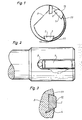
- Fig. 1 eine Stirnseitenansicht des Reibahlen-Messerkopfes,
- Fig. 2 eine Seitenansicht des Messerkopfes,
- Fig. 3 ein Querschnitt durch eine Führungsleiste in vergrößertem Maßstab.
- Am Umfang des Messerkopfes 3 einer als Einmesser-Reibahle ausgebildeten Reibahle sind zwei Führungsleisten 1 in prismatischen Aussparungen 2 eingesetzt. Die Führungsleisten 1 weisen ein im wesentlichen trapezförmiges Profil mit zwei Flanken 11 und einer zylindrisch gekrümmten Außenfläche 12 auf. In die einen schwalbeschwanzförmigen Querschnitt aufweisenden Aussparungen 2 werden die Führungsleisten 1 von der Stirnseite des Messerkopfes 3 her eingesetzt und liegen mit ihrer rückseitigen Stirnfläche gegen einen Anschlag 5 an. Um die axiale Lage der Führungsleisten 1 in den Aussparungen 2 zu sichern, sind in eine Seitenfläche der Aussparungen 2 in randoffenen zylindrischen Bohrungen elastische Körper 4 eingesetzt, die über diese Seitenfläche etwas überstehen und nach Einsetzen der Führungsleisten 1 klemmend gegen diese anliegen.
Claims (6)
Priority Applications (1)
| Application Number | Priority Date | Filing Date | Title |
|---|---|---|---|
| AT84101052T ATE27236T1 (de) | 1983-03-02 | 1984-02-02 | Reibahle. |
Applications Claiming Priority (2)
| Application Number | Priority Date | Filing Date | Title |
|---|---|---|---|
| DE3307398 | 1983-03-02 | ||
| DE3307398A DE3307398C1 (de) | 1983-03-02 | 1983-03-02 | Reibahle |
Publications (3)
| Publication Number | Publication Date |
|---|---|
| EP0120226A2 true EP0120226A2 (de) | 1984-10-03 |
| EP0120226A3 EP0120226A3 (en) | 1985-08-28 |
| EP0120226B1 EP0120226B1 (de) | 1987-05-20 |
Family
ID=6192317
Family Applications (1)
| Application Number | Title | Priority Date | Filing Date |
|---|---|---|---|
| EP84101052A Expired EP0120226B1 (de) | 1983-03-02 | 1984-02-02 | Reibahle |
Country Status (9)
| Country | Link |
|---|---|
| US (1) | US4571130A (de) |
| EP (1) | EP0120226B1 (de) |
| JP (1) | JPH0620664B2 (de) |
| AT (1) | ATE27236T1 (de) |
| CA (1) | CA1211963A (de) |
| DD (1) | DD230807A1 (de) |
| DE (2) | DE3307398C1 (de) |
| ES (1) | ES277703Y (de) |
| SU (1) | SU1351513A3 (de) |
Cited By (1)
| Publication number | Priority date | Publication date | Assignee | Title |
|---|---|---|---|---|
| DE102010052845A1 (de) * | 2010-11-29 | 2012-05-31 | Kennametal Inc. | Rotierendes Schneidwerkzeug und Führungseinsatz hierfür |
Families Citing this family (4)
| Publication number | Priority date | Publication date | Assignee | Title |
|---|---|---|---|---|
| DE19621813B4 (de) * | 1996-05-31 | 2007-08-09 | August Beck Gmbh & Co | Reibahle |
| SE517446C2 (sv) * | 1999-06-21 | 2002-06-04 | Sandvik Ab | Stödlist/Ledare |
| JP4961245B2 (ja) * | 2007-04-02 | 2012-06-27 | ユニタック株式会社 | 深穴切削装置 |
| SE533277C2 (sv) * | 2008-12-19 | 2010-08-10 | Sandvik Intellectual Property | Borrkropp samt stödlist härför |
Family Cites Families (10)
| Publication number | Priority date | Publication date | Assignee | Title |
|---|---|---|---|---|
| US1300325A (en) * | 1918-04-08 | 1919-04-15 | Frederick Baumann | Finishing-tool. |
| US2380517A (en) * | 1943-10-22 | 1945-07-31 | Gordon John | Spring blade reamer |
| US2869405A (en) * | 1957-06-05 | 1959-01-20 | American Iron & Machine Works | Trepanning head |
| DE1153223B (de) * | 1958-09-11 | 1963-08-22 | Heidenreich & Harbeck Werkzeug | Bohrwerkzeug zum Bohren langer Bohrloecher |
| GB1080155A (en) * | 1965-04-28 | 1967-08-23 | Apperley Honing Ltd | Improvements in or relating to honing mandrels |
| US3422706A (en) * | 1965-08-06 | 1969-01-21 | Int Nickel Co | Gun drill |
| DE1752151C3 (de) * | 1968-04-10 | 1974-01-10 | Mapal Dr. Kress Kg, 7080 Aalen | Einmesserreibahle mit auswechselbarem Messer |
| US3658434A (en) * | 1970-04-03 | 1972-04-25 | Erickson Tool Co | Anti-chatter guides for spade drill |
| GB1487183A (en) * | 1973-12-08 | 1977-09-28 | Toolmasters & Tech Dev Ltd | Boring heads |
| DE2522565B2 (de) * | 1975-05-22 | 1977-09-15 | Botek Prazisionsbohrtechnik Schur & Co, 7419 Riederich | Tiefbohrwerkzeug |
-
1983
- 1983-03-02 DE DE3307398A patent/DE3307398C1/de not_active Expired
-
1984
- 1984-02-02 AT AT84101052T patent/ATE27236T1/de not_active IP Right Cessation
- 1984-02-02 DE DE8484101052T patent/DE3463734D1/de not_active Expired
- 1984-02-02 EP EP84101052A patent/EP0120226B1/de not_active Expired
- 1984-02-23 ES ES1984277703U patent/ES277703Y/es not_active Expired
- 1984-02-23 US US06/582,932 patent/US4571130A/en not_active Expired - Lifetime
- 1984-02-28 JP JP59035449A patent/JPH0620664B2/ja not_active Expired - Lifetime
- 1984-02-29 CA CA000448575A patent/CA1211963A/en not_active Expired
- 1984-03-01 SU SU843707306A patent/SU1351513A3/ru active
- 1984-03-01 DD DD84260467A patent/DD230807A1/de not_active IP Right Cessation
Cited By (3)
| Publication number | Priority date | Publication date | Assignee | Title |
|---|---|---|---|---|
| DE102010052845A1 (de) * | 2010-11-29 | 2012-05-31 | Kennametal Inc. | Rotierendes Schneidwerkzeug und Führungseinsatz hierfür |
| US8801343B2 (en) | 2010-11-29 | 2014-08-12 | Kennametal Inc. | Rotating cutting tool and guide insert therefor |
| DE102010052845B4 (de) * | 2010-11-29 | 2015-01-15 | Kennametal Inc. | Rotierendes Schneidwerkzeug und Führungseinsatz hierfür |
Also Published As
| Publication number | Publication date |
|---|---|
| JPH0620664B2 (ja) | 1994-03-23 |
| ATE27236T1 (de) | 1987-06-15 |
| DE3307398C1 (de) | 1984-06-20 |
| EP0120226B1 (de) | 1987-05-20 |
| US4571130A (en) | 1986-02-18 |
| EP0120226A3 (en) | 1985-08-28 |
| ES277703U (es) | 1984-07-16 |
| ES277703Y (es) | 1985-02-16 |
| SU1351513A3 (ru) | 1987-11-07 |
| CA1211963A (en) | 1986-09-30 |
| DD230807A1 (de) | 1985-12-11 |
| DE3463734D1 (en) | 1987-06-25 |
| JPS59161225A (ja) | 1984-09-12 |
Similar Documents
| Publication | Publication Date | Title |
|---|---|---|
| DE2614599C3 (de) | Reibahle für die Bearbeitung eng tolerierter Bohrungen | |
| DE2500216B2 (de) | Werkzeug zum Ausschneiden von Scheiben aus Blech o.dgl | |
| DE2411759B2 (de) | Schneidwerkzeug fuer die spanabhebende bearbeitung | |
| EP0385280A1 (de) | Innendrehmeissel | |
| DE3226799C1 (de) | Einmesser-Reibahle | |
| DE2736612C3 (de) | Wendeplatten-Messerkopf | |
| DE7602409U1 (de) | Einbauhalter fuer ein schneidwerkzeug | |
| DE8908545U1 (de) | Befestigungselement, insbesondere für eine Kugel-Gewindespindel | |
| EP0120226A2 (de) | Reibahle | |
| EP0261465A2 (de) | Gewinde-Fräswerkzeug | |
| EP0791421A1 (de) | Verbindung zwischen einem Schneidenhalter und einem Werkzeugträger eines Ausdrehkopfes | |
| DE3533125A1 (de) | Fraeser fuer das hochgeschwindigkeitsfraesen | |
| DE3639774A1 (de) | Schraubvorrichtung | |
| DE3211460A1 (de) | Zerspanungswerkzeug | |
| DE2539363C2 (de) | Blendrahmenschenkel | |
| DE102005019945A1 (de) | Trägerwerkzeug für eine Schneidplatte mit zwei Schneiden und Schneidplatte mit zwei Schneiden | |
| DE2800884A1 (de) | Vorrichtung zur befestigung eines schneideinsatzes an einem halter | |
| DE970979C (de) | Fraeser bzw. Raeumwerkzeug mit in Quernuten eines Werkzeugkoerpers eingesetzten Zaehnen bzw. Zahnleisten | |
| DE2609617B2 (de) | Bohrstange, insbesondere für die Metallbearbeitung | |
| DE19631578A1 (de) | Fräsplatte für Fräswerkzeuge | |
| DE1752202A1 (de) | Schneidwerkzeugeinsatz und Halter fuer diesen | |
| DE9319460U1 (de) | Schneidplatten-Befestigungsvorrichtung | |
| DE19855471C2 (de) | Werkzeug zur spanabtragenden Feinbearbeitung von Bohrungsoberflächen mit wenigstens einer austauschbaren Schneidplatte | |
| DE2000186C3 (de) | Werkzeugeinsatz für Bohrstangen und dgl. Werkzeughalter | |
| DE2552874A1 (de) | Werkzeugkopf mit mindestens einem auswechselbaren messer |
Legal Events
| Date | Code | Title | Description |
|---|---|---|---|
| PUAI | Public reference made under article 153(3) epc to a published international application that has entered the european phase |
Free format text: ORIGINAL CODE: 0009012 |
|
| AK | Designated contracting states |
Designated state(s): AT BE CH DE FR GB IT LI NL SE |
|
| PUAL | Search report despatched |
Free format text: ORIGINAL CODE: 0009013 |
|
| AK | Designated contracting states |
Designated state(s): AT BE CH DE FR GB IT LI NL SE |
|
| 17P | Request for examination filed |
Effective date: 19850710 |
|
| 17Q | First examination report despatched |
Effective date: 19861015 |
|
| GRAA | (expected) grant |
Free format text: ORIGINAL CODE: 0009210 |
|
| AK | Designated contracting states |
Kind code of ref document: B1 Designated state(s): AT BE CH DE FR GB IT LI NL SE |
|
| REF | Corresponds to: |
Ref document number: 27236 Country of ref document: AT Date of ref document: 19870615 Kind code of ref document: T |
|
| REF | Corresponds to: |
Ref document number: 3463734 Country of ref document: DE Date of ref document: 19870625 |
|
| ET | Fr: translation filed | ||
| ITF | It: translation for a ep patent filed | ||
| PLBE | No opposition filed within time limit |
Free format text: ORIGINAL CODE: 0009261 |
|
| STAA | Information on the status of an ep patent application or granted ep patent |
Free format text: STATUS: NO OPPOSITION FILED WITHIN TIME LIMIT |
|
| 26N | No opposition filed | ||
| PGFP | Annual fee paid to national office [announced via postgrant information from national office to epo] |
Ref country code: AT Payment date: 19930114 Year of fee payment: 10 |
|
| PGFP | Annual fee paid to national office [announced via postgrant information from national office to epo] |
Ref country code: CH Payment date: 19930119 Year of fee payment: 10 |
|
| PGFP | Annual fee paid to national office [announced via postgrant information from national office to epo] |
Ref country code: BE Payment date: 19930126 Year of fee payment: 10 |
|
| ITTA | It: last paid annual fee | ||
| PGFP | Annual fee paid to national office [announced via postgrant information from national office to epo] |
Ref country code: NL Payment date: 19930228 Year of fee payment: 10 |
|
| PG25 | Lapsed in a contracting state [announced via postgrant information from national office to epo] |
Ref country code: AT Effective date: 19940202 |
|
| PG25 | Lapsed in a contracting state [announced via postgrant information from national office to epo] |
Ref country code: LI Effective date: 19940228 Ref country code: CH Effective date: 19940228 Ref country code: BE Effective date: 19940228 |
|
| BERE | Be: lapsed |
Owner name: MAPAL Effective date: 19940228 |
|
| PG25 | Lapsed in a contracting state [announced via postgrant information from national office to epo] |
Ref country code: NL Effective date: 19940901 |
|
| NLV4 | Nl: lapsed or anulled due to non-payment of the annual fee | ||
| REG | Reference to a national code |
Ref country code: CH Ref legal event code: PL |
|
| EAL | Se: european patent in force in sweden |
Ref document number: 84101052.3 |
|
| PGFP | Annual fee paid to national office [announced via postgrant information from national office to epo] |
Ref country code: SE Payment date: 20010223 Year of fee payment: 18 |
|
| REG | Reference to a national code |
Ref country code: GB Ref legal event code: IF02 |
|
| PG25 | Lapsed in a contracting state [announced via postgrant information from national office to epo] |
Ref country code: SE Free format text: LAPSE BECAUSE OF NON-PAYMENT OF DUE FEES Effective date: 20020203 |
|
| PGFP | Annual fee paid to national office [announced via postgrant information from national office to epo] |
Ref country code: FR Payment date: 20020211 Year of fee payment: 19 |
|
| PGFP | Annual fee paid to national office [announced via postgrant information from national office to epo] |
Ref country code: GB Payment date: 20020220 Year of fee payment: 19 |
|
| PGFP | Annual fee paid to national office [announced via postgrant information from national office to epo] |
Ref country code: DE Payment date: 20020429 Year of fee payment: 19 |
|
| EUG | Se: european patent has lapsed |
Ref document number: 84101052.3 |
|
| PG25 | Lapsed in a contracting state [announced via postgrant information from national office to epo] |
Ref country code: GB Free format text: LAPSE BECAUSE OF NON-PAYMENT OF DUE FEES Effective date: 20030202 |
|
| PG25 | Lapsed in a contracting state [announced via postgrant information from national office to epo] |
Ref country code: DE Free format text: LAPSE BECAUSE OF NON-PAYMENT OF DUE FEES Effective date: 20030902 |
|
| GBPC | Gb: european patent ceased through non-payment of renewal fee | ||
| PG25 | Lapsed in a contracting state [announced via postgrant information from national office to epo] |
Ref country code: FR Free format text: LAPSE BECAUSE OF NON-PAYMENT OF DUE FEES Effective date: 20031031 |
|
| REG | Reference to a national code |
Ref country code: FR Ref legal event code: ST |