EP0120277A1 - Pressmuffe für die Reparatur eines Rohres - Google Patents
Pressmuffe für die Reparatur eines Rohres Download PDFInfo
- Publication number
- EP0120277A1 EP0120277A1 EP84101716A EP84101716A EP0120277A1 EP 0120277 A1 EP0120277 A1 EP 0120277A1 EP 84101716 A EP84101716 A EP 84101716A EP 84101716 A EP84101716 A EP 84101716A EP 0120277 A1 EP0120277 A1 EP 0120277A1
- Authority
- EP
- European Patent Office
- Prior art keywords
- tube
- sleeve
- head
- ring member
- ring
- Prior art date
- Legal status (The legal status is an assumption and is not a legal conclusion. Google has not performed a legal analysis and makes no representation as to the accuracy of the status listed.)
- Withdrawn
Links
- 230000006835 compression Effects 0.000 title claims abstract description 17
- 238000007906 compression Methods 0.000 title claims abstract description 17
- 238000007789 sealing Methods 0.000 claims abstract description 10
- 239000002184 metal Substances 0.000 claims description 5
- 229910052751 metal Inorganic materials 0.000 claims description 5
- PCHJSUWPFVWCPO-UHFFFAOYSA-N gold Chemical compound [Au] PCHJSUWPFVWCPO-UHFFFAOYSA-N 0.000 claims description 3
- 239000010931 gold Substances 0.000 claims description 3
- 229910052737 gold Inorganic materials 0.000 claims description 3
- 230000009972 noncorrosive effect Effects 0.000 claims description 3
- 239000000463 material Substances 0.000 claims description 2
- 230000003993 interaction Effects 0.000 abstract description 3
- 230000003100 immobilizing effect Effects 0.000 abstract description 2
- 239000012530 fluid Substances 0.000 description 6
- 230000007547 defect Effects 0.000 description 5
- XLYOFNOQVPJJNP-UHFFFAOYSA-N water Substances O XLYOFNOQVPJJNP-UHFFFAOYSA-N 0.000 description 4
- 238000009434 installation Methods 0.000 description 3
- 230000014759 maintenance of location Effects 0.000 description 3
- 230000002285 radioactive effect Effects 0.000 description 3
- 230000000694 effects Effects 0.000 description 2
- 239000007788 liquid Substances 0.000 description 2
- 230000015572 biosynthetic process Effects 0.000 description 1
- 230000008602 contraction Effects 0.000 description 1
- 239000002826 coolant Substances 0.000 description 1
- 230000001351 cycling effect Effects 0.000 description 1
- 230000006866 deterioration Effects 0.000 description 1
- 230000003292 diminished effect Effects 0.000 description 1
- 230000001771 impaired effect Effects 0.000 description 1
- 238000003780 insertion Methods 0.000 description 1
- 230000037431 insertion Effects 0.000 description 1
- 238000012423 maintenance Methods 0.000 description 1
- 238000000034 method Methods 0.000 description 1
- 230000036316 preload Effects 0.000 description 1
- 230000000246 remedial effect Effects 0.000 description 1
- 239000010802 sludge Substances 0.000 description 1
Images
Classifications
-
- F—MECHANICAL ENGINEERING; LIGHTING; HEATING; WEAPONS; BLASTING
- F16—ENGINEERING ELEMENTS AND UNITS; GENERAL MEASURES FOR PRODUCING AND MAINTAINING EFFECTIVE FUNCTIONING OF MACHINES OR INSTALLATIONS; THERMAL INSULATION IN GENERAL
- F16L—PIPES; JOINTS OR FITTINGS FOR PIPES; SUPPORTS FOR PIPES, CABLES OR PROTECTIVE TUBING; MEANS FOR THERMAL INSULATION IN GENERAL
- F16L55/00—Devices or appurtenances for use in, or in connection with, pipes or pipe systems
- F16L55/18—Appliances for use in repairing pipes
-
- F—MECHANICAL ENGINEERING; LIGHTING; HEATING; WEAPONS; BLASTING
- F16—ENGINEERING ELEMENTS AND UNITS; GENERAL MEASURES FOR PRODUCING AND MAINTAINING EFFECTIVE FUNCTIONING OF MACHINES OR INSTALLATIONS; THERMAL INSULATION IN GENERAL
- F16L—PIPES; JOINTS OR FITTINGS FOR PIPES; SUPPORTS FOR PIPES, CABLES OR PROTECTIVE TUBING; MEANS FOR THERMAL INSULATION IN GENERAL
- F16L55/00—Devices or appurtenances for use in, or in connection with, pipes or pipe systems
- F16L55/10—Means for stopping flow in pipes or hoses
- F16L55/12—Means for stopping flow in pipes or hoses by introducing into the pipe a member expandable in situ
- F16L55/128—Means for stopping flow in pipes or hoses by introducing into the pipe a member expandable in situ introduced axially into the pipe or hose
- F16L55/13—Means for stopping flow in pipes or hoses by introducing into the pipe a member expandable in situ introduced axially into the pipe or hose the closure device being a plug fixed by plastic deformation
-
- F—MECHANICAL ENGINEERING; LIGHTING; HEATING; WEAPONS; BLASTING
- F16—ENGINEERING ELEMENTS AND UNITS; GENERAL MEASURES FOR PRODUCING AND MAINTAINING EFFECTIVE FUNCTIONING OF MACHINES OR INSTALLATIONS; THERMAL INSULATION IN GENERAL
- F16L—PIPES; JOINTS OR FITTINGS FOR PIPES; SUPPORTS FOR PIPES, CABLES OR PROTECTIVE TUBING; MEANS FOR THERMAL INSULATION IN GENERAL
- F16L55/00—Devices or appurtenances for use in, or in connection with, pipes or pipe systems
- F16L55/10—Means for stopping flow in pipes or hoses
- F16L55/12—Means for stopping flow in pipes or hoses by introducing into the pipe a member expandable in situ
- F16L55/128—Means for stopping flow in pipes or hoses by introducing into the pipe a member expandable in situ introduced axially into the pipe or hose
- F16L55/136—Means for stopping flow in pipes or hoses by introducing into the pipe a member expandable in situ introduced axially into the pipe or hose the closure device being a plug fixed by radially expanding or deforming a split ring, hooks or the like
-
- F—MECHANICAL ENGINEERING; LIGHTING; HEATING; WEAPONS; BLASTING
- F28—HEAT EXCHANGE IN GENERAL
- F28F—DETAILS OF HEAT-EXCHANGE AND HEAT-TRANSFER APPARATUS, OF GENERAL APPLICATION
- F28F11/00—Arrangements for sealing leaky tubes and conduits
- F28F11/02—Arrangements for sealing leaky tubes and conduits using obturating elements, e.g. washers, inserted and operated independently of each other
-
- Y—GENERAL TAGGING OF NEW TECHNOLOGICAL DEVELOPMENTS; GENERAL TAGGING OF CROSS-SECTIONAL TECHNOLOGIES SPANNING OVER SEVERAL SECTIONS OF THE IPC; TECHNICAL SUBJECTS COVERED BY FORMER USPC CROSS-REFERENCE ART COLLECTIONS [XRACs] AND DIGESTS
- Y10—TECHNICAL SUBJECTS COVERED BY FORMER USPC
- Y10T—TECHNICAL SUBJECTS COVERED BY FORMER US CLASSIFICATION
- Y10T29/00—Metal working
- Y10T29/49—Method of mechanical manufacture
- Y10T29/4935—Heat exchanger or boiler making
- Y10T29/49352—Repairing, converting, servicing or salvaging
-
- Y—GENERAL TAGGING OF NEW TECHNOLOGICAL DEVELOPMENTS; GENERAL TAGGING OF CROSS-SECTIONAL TECHNOLOGIES SPANNING OVER SEVERAL SECTIONS OF THE IPC; TECHNICAL SUBJECTS COVERED BY FORMER USPC CROSS-REFERENCE ART COLLECTIONS [XRACs] AND DIGESTS
- Y10—TECHNICAL SUBJECTS COVERED BY FORMER USPC
- Y10T—TECHNICAL SUBJECTS COVERED BY FORMER US CLASSIFICATION
- Y10T29/00—Metal working
- Y10T29/49—Method of mechanical manufacture
- Y10T29/49718—Repairing
- Y10T29/49732—Repairing by attaching repair preform, e.g., remaking, restoring, or patching
- Y10T29/49734—Repairing by attaching repair preform, e.g., remaking, restoring, or patching and removing damaged material
- Y10T29/49735—Mechanically attaching preform with separate fastener
Definitions
- the present invention relates to tube repair, and more particularly to securing a plug or bypass member within a tube.
- Nuclear power steam supply systems particulary the pressurized water type, include a large steam generator heat exchanger having tube and shell sides separated by a thick tube sheet. If sometimes is necessary to reduce leakage from the tube to shell sides In order to reduce the level of radioactivity ultimatey released to the environment. Repairing the tube leaks is a complex undertaking because the steam generator, even when drained, is radioactive In the area of the tube sheet. Accordingly, such repair operations must be performed very quickly by hand, or be adapted for remote, automated Installation.
- the components of the inventive device include an elongated tension member having an enlarged head portion at its upper or lead end, and a stem portion at the other end.
- a generally cylindrical ring member is disposed about the lower portion of the tension member, and a ferrule-type, radially expandable compression member or sleeve is interposed between the enlarged head and the ring.
- Means are included for immobilizing the ring member against the tube sheet while drawing down the tension member head. Tapered surfaces on the sleeve, the head, and the ring produce a wedge-like Interaction therebetween, such that the upper and lower surfaces of the sleeve expand outwardly into sealing engagement with the adjacent tube wall.
- the stem portion extents below the tube sheet and is adapted to support the ring and effect the tension member draw-down.
- the advantages of the present invention include quick installation time, on the order of 30 seconds per plug or bypass assembly.
- the plug or bypass may be removed and replaced with, for example, a longer bypass.
- a constant preload under both hot and cold conditions is maintained as a result of the preferred use of the tube material for the repair device components.
- both ends of the compression sleeve are sealed against the tube at the same time, thereby avoiding the time delay and procedural complexities associated with multi-step sealing operations.
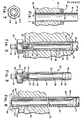
- Figure 1 shows a portion of a typical tube sheet 12 of a heat exchanger 10, such as a nuclear steam generator, wherein a plurality of generally cylindrical metal tubes 14 are secured to the tube sheet 12.
- the tube walls 16 are generally relatively thin and are usually sealed at 18 to the bottom of the tube sheet 12.
- the plenum region generally shown as 20 normally contains a liquid at high temperature and pressure, which is forced through the tubes 14 such that water surrounding the tubes 14 (not shown) is converted to steam.
- FIGS 2 and 3 show one embodiment of the invention wherein a tube repair plug assembly 26 may be quickly and effectively inserted within and secured to the tube to prevent entry of primary water from the plenum region 20.
- the plug assembly includes a generally cylindrical tension member 28 that Is preferably machined as a unitary piece.
- Member 28 Includes an upper expander means, or enlarged head, 30, a generally cylindrical body portion 32, and a stem portion 34, the stem portion preferably having screw thread 36 and retention head 38 at the lower end thereof.
- the tension member 28 is preferably bored and counterbored from the head 30 Into the stem, as shown In Figure 2. This reduces the weight of the plug device and provides some degree of flexibility for facilitating the interaction of the head portion 30 required to effect the seal as described below. Also, the tension member thermal expansion and contraction will more closely resemble that of the tube.
- the plug assembly 26 further includes a lower expander ring 40 concentrically disposed about the lower end of the body portion 32, the ring member Including a flange 42 or other means for cooperating with the tube sheet lower surface to limit the upward travel of the expander ring relative to the tube sheet 12.
- the third major component of the plug assembly 26 is a generally cylindrical compression sleever 44 carried between the expander head 30 and the expander ring 40.
- the compression sleeve surrounds the body portion 32 of the tension member and Includes upper tapered surfaces 46 and lower tapered surfaces 48 for interacting with oppositely facing, overlapping tapered surfaces 50 on the expander head 30 and 52 on the lower expander ring 40.
- the device or assembly 26 is shown to be secured to the tube wall 16 by drawing down the tension member 28 to longitudinally compress the sleeve member 44 against the ring 40.
- the compression forces cause the sleeve to expand against the tube wall 16.
- the stem portion 34 of the tension member includes means, such as nut 54, for limiting the downward travel of the ring member 40 while permitting the tension member head portion 30 to be drawn downward relative to the ring.
- the flange 42 of ring member 40 Is inittally spaced slightly below the tube sheet lower surface, so that as the nut 54 is turned, and the head 30 is drawn, the ring member advances a predetermined distance toward the sleeve 44, which distance is limited by the flange contact with the tube sheet.
- tension member 28, compression member 44, and ring member 40 are operatively arranged such that when the tension member is drawn downward the oppositely facing tapered surfaces 46,50, and 48,52 advance wedge-like over each other, radially expanding the upper and lower circumferential outer end surfaces 62 and 64, respectively, of the compression sleeve member 44.
- the means for limiting the downward travel of the ring 40 and the means adapted to draw the tension member 28 downward are preferably provided by the same tensioning nut 54, which is torqued along the screw thread 36 while a retention tool (not shown) is secured on the retention head 38 to prevent rotation of the tension member 28 while the device 26 is being installed.
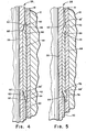
- the cooperation between the expander head 30, expander ring 40, and sleeve member 44 are shown in detail In Figures 4 and 5.
- the lower expander wedge 60 on the expansion ring 40 has an upwardly tapered surface 52 that overlaps with the downward facing tapered surface 48 on the Inside of the lower end of the compression member 44.
- the taper 50 on the expander head 30 is downward facing while the sleeve upper end taper 46 is upward facing.
- the outside circumferential surface 62,64 at the upper and lower ends of the sleeve, which are urged against the tube wall 16, are coated with a soft, non-corrosive metal, such as 24 karat gold.
- outer circumferential sealing surfaces 62,64 are preferably in the form of Integral rims defined by circumferential grooves 66,66' near the upper and lower ends of the sleeve.
- the grooves 66,66' are shown Just below, and above, the elevations 68,68', respectively, where the tapered surfaces 46,48 begin on the sleeve 44.
- Figure 5 shows the resulting upper primary seal surface 70 and upper secondary seal surface 72, and corresponding lower primary 74 and lower secondary 76 seal surfaces.
- the primary seals 70,74 are effected by plastic deformation of the rims 62 and 64 against the adjacent tube wall 16, which is also deformed at, for example, 16'.
- Grooves 66,66' provide flexibility at the ends of the compression sleeve member whereby the outward expansion forces available from the torquing of the nut 54 (see Figure 2) bend the upper and lower portions of the sleeve sufficiently to form leaktight, permanent primary seats.
- the secondary seals which are less effective, provide a limited backup In embodiments having the groove.
- the compression sleeve member 44 may optionally have a different shape from that Illustrated, so long as the extremities that interact with the tension and ring members include a tapered inner surface and an outer circumference adapted to form sealing surfaces when expanded against the tube wall.
- "tapered” is not limited to inclined plane, but includes other shapes that can slide relative to each other.
- the steam generator may be operated without fear that radioactive liquid will penetrate the plug and enter the secondary coolant through defect 22 (see Figure 1).
- It may be desirable or necessary for the plug to be subsequently removed This may arise when so many plugs have been inserted, over a period of years, that the steam generator heat transfer capability has been diminished and thus the power output of the unit must be reduced. It may thus be cost- effective to remove plugs and reuse the tubes after Installing bypass conduits.
- the plug assembly shown in Figure 2 can readily be removed by loosening the nut 54 and pulling down, if necessary, on the expander ring flange 42.
- the rims 62,64 will return to the positions shown In Figure 4, enabling the operator to withdraw the entire plug assembly 26 from the tube 14.
- a bypass conduit assembly 80 is shown with the lower seal 82 formed within the tube sheet 12 and the upper seal 84 formed above the tube sheet, beyond the location of the tube defect 22 ( Figure 1).
- the tube sheet may be up to about 20 inches In thickness, and the bypass conduit assembly 80 may be up to about 40 inches in length.
- the steam generator tube Is typically 3/4 to 7/8 Inch O.D.
- the bypass assembly 80 includes the same components previously described with respect to the tube plug assembly 26, except that the inner tension member 86 is hollow throughout Its length.
- the function of retaining the tension member 86 while the nut 54a is torqued, is provided by a slot 88 on the stem 90 as shown in Figure 7.
- a screw driver or equivalent means (not shown) Is inserted into the slot while the nut is turned.
Landscapes
- Engineering & Computer Science (AREA)
- General Engineering & Computer Science (AREA)
- Mechanical Engineering (AREA)
- Physics & Mathematics (AREA)
- Thermal Sciences (AREA)
- Pipe Accessories (AREA)
- Heat-Exchange Devices With Radiators And Conduit Assemblies (AREA)
Applications Claiming Priority (2)
| Application Number | Priority Date | Filing Date | Title |
|---|---|---|---|
| US477292 | 1983-03-21 | ||
| US06/477,292 US4485847A (en) | 1983-03-21 | 1983-03-21 | Compression sleeve tube repair |
Publications (1)
| Publication Number | Publication Date |
|---|---|
| EP0120277A1 true EP0120277A1 (de) | 1984-10-03 |
Family
ID=23895315
Family Applications (1)
| Application Number | Title | Priority Date | Filing Date |
|---|---|---|---|
| EP84101716A Withdrawn EP0120277A1 (de) | 1983-03-21 | 1984-02-20 | Pressmuffe für die Reparatur eines Rohres |
Country Status (5)
| Country | Link |
|---|---|
| US (1) | US4485847A (de) |
| EP (1) | EP0120277A1 (de) |
| JP (1) | JPS59180296A (de) |
| KR (1) | KR840008050A (de) |
| ES (1) | ES8705687A1 (de) |
Cited By (12)
| Publication number | Priority date | Publication date | Assignee | Title |
|---|---|---|---|---|
| EP0186489A3 (en) * | 1984-12-27 | 1987-09-16 | Westinghouse Electric Corporation | Device and method for protecting defect regions of steam generator tubes during removal |
| EP0270053A1 (de) * | 1986-12-01 | 1988-06-08 | Westinghouse Electric Corporation | Gerät und Verfahren zum Verschliessen eines Rohres |
| EP0270973A1 (de) * | 1986-12-01 | 1988-06-15 | Westinghouse Electric Corporation | Vermuffungsvorrichtung und Verfharen unter Verwendung eines hydraulisch unterstützten Muffenaufweiters |
| US4799305A (en) * | 1984-12-27 | 1989-01-24 | Westinghouse Electric Corp. | Tube protection device |
| US4831703A (en) * | 1986-12-01 | 1989-05-23 | Westinghouse Electric Corp. | Apparatus and method for plugging a tube |
| US5079837A (en) * | 1989-03-03 | 1992-01-14 | Siemes Aktiengesellschaft | Repair lining and method for repairing a heat exchanger tube with the repair lining |
| KR100648741B1 (ko) | 2004-08-02 | 2006-11-23 | 롬 앤드 하스 캄파니 | 플로우 스루 튜브 플러그를 이용하여 튜브를 수리하는 방법, 라미네이트된 튜브시트를 수리 및 형성하는 방법, 및 플로우 스루 튜브 플러그를 구비한 장치 |
| WO2011123590A1 (en) * | 2010-03-31 | 2011-10-06 | Saudi Arabian Oil Company | Plug kit for pressured components |
| WO2011148044A3 (en) * | 2010-05-28 | 2012-01-26 | Metso Power Oy | A flue gas air preheater, and a method for installation, as well as an air pipe component for a flue gas air preheater |
| US9541337B2 (en) | 2010-03-31 | 2017-01-10 | Saudi Arabian Oil Company | Assembly for plugging a tube |
| IT202000001588A1 (it) * | 2020-01-28 | 2021-07-28 | Hudson Italiana Fbm | Tappo per sigillare tubi di scambiatori a fascio tubiero e mantello |
| CN113404970A (zh) * | 2021-07-27 | 2021-09-17 | 天津久安机械制造有限责任公司 | 一种管道堵漏装置 |
Families Citing this family (72)
| Publication number | Priority date | Publication date | Assignee | Title |
|---|---|---|---|---|
| US4592391A (en) * | 1984-01-19 | 1986-06-03 | Combustion Engineering, Inc. | Tube sleeve |
| GB8405402D0 (en) * | 1984-03-01 | 1984-04-04 | Dom Holdings Plc | Expansion anchor |
| US4793382A (en) * | 1984-04-04 | 1988-12-27 | Raychem Corporation | Assembly for repairing a damaged pipe |
| US4713870A (en) * | 1985-03-26 | 1987-12-22 | Raychem Corporation | Pipe repair sleeve apparatus and method of repairing a damaged pipe |
| FR2598202B1 (fr) * | 1986-04-30 | 1990-02-09 | Framatome Sa | Procede de chemisage d'un tube peripherique d'un generateur de vapeur. |
| US4746240A (en) * | 1987-04-01 | 1988-05-24 | General Motors Corporation | Self crimping connection for inner and outer members and method of assembling the same |
| US5372391A (en) * | 1993-02-22 | 1994-12-13 | The United States Of America As Represented By The United States Department Of Energy | Internal pipe attachment mechanism |
| US5848874A (en) * | 1997-05-13 | 1998-12-15 | United Technologies Corporation | Gas turbine stator vane assembly |
| GB2343691B (en) | 1998-11-16 | 2003-05-07 | Shell Int Research | Isolation of subterranean zones |
| US7603758B2 (en) | 1998-12-07 | 2009-10-20 | Shell Oil Company | Method of coupling a tubular member |
| AU6981001A (en) | 1998-11-16 | 2002-01-02 | Shell Oil Co | Radial expansion of tubular members |
| US6823937B1 (en) | 1998-12-07 | 2004-11-30 | Shell Oil Company | Wellhead |
| US6575240B1 (en) | 1998-12-07 | 2003-06-10 | Shell Oil Company | System and method for driving pipe |
| US7121352B2 (en) | 1998-11-16 | 2006-10-17 | Enventure Global Technology | Isolation of subterranean zones |
| US7357188B1 (en) | 1998-12-07 | 2008-04-15 | Shell Oil Company | Mono-diameter wellbore casing |
| US6712154B2 (en) | 1998-11-16 | 2004-03-30 | Enventure Global Technology | Isolation of subterranean zones |
| US6634431B2 (en) | 1998-11-16 | 2003-10-21 | Robert Lance Cook | Isolation of subterranean zones |
| US7231985B2 (en) | 1998-11-16 | 2007-06-19 | Shell Oil Company | Radial expansion of tubular members |
| US6604763B1 (en) | 1998-12-07 | 2003-08-12 | Shell Oil Company | Expandable connector |
| US6745845B2 (en) | 1998-11-16 | 2004-06-08 | Shell Oil Company | Isolation of subterranean zones |
| US6557640B1 (en) | 1998-12-07 | 2003-05-06 | Shell Oil Company | Lubrication and self-cleaning system for expansion mandrel |
| US6640903B1 (en) | 1998-12-07 | 2003-11-04 | Shell Oil Company | Forming a wellbore casing while simultaneously drilling a wellbore |
| US6739392B2 (en) | 1998-12-07 | 2004-05-25 | Shell Oil Company | Forming a wellbore casing while simultaneously drilling a wellbore |
| US7363984B2 (en) | 1998-12-07 | 2008-04-29 | Enventure Global Technology, Llc | System for radially expanding a tubular member |
| US7185710B2 (en) | 1998-12-07 | 2007-03-06 | Enventure Global Technology | Mono-diameter wellbore casing |
| US7195064B2 (en) | 1998-12-07 | 2007-03-27 | Enventure Global Technology | Mono-diameter wellbore casing |
| CA2310878A1 (en) | 1998-12-07 | 2000-12-07 | Shell Internationale Research Maatschappij B.V. | Lubrication and self-cleaning system for expansion mandrel |
| US7552776B2 (en) | 1998-12-07 | 2009-06-30 | Enventure Global Technology, Llc | Anchor hangers |
| GB2344606B (en) | 1998-12-07 | 2003-08-13 | Shell Int Research | Forming a wellbore casing by expansion of a tubular member |
| AU770359B2 (en) | 1999-02-26 | 2004-02-19 | Shell Internationale Research Maatschappij B.V. | Liner hanger |
| US7055608B2 (en) | 1999-03-11 | 2006-06-06 | Shell Oil Company | Forming a wellbore casing while simultaneously drilling a wellbore |
| CA2306656C (en) | 1999-04-26 | 2006-06-06 | Shell Internationale Research Maatschappij B.V. | Expandable connector for borehole tubes |
| US7350563B2 (en) | 1999-07-09 | 2008-04-01 | Enventure Global Technology, L.L.C. | System for lining a wellbore casing |
| US7048067B1 (en) | 1999-11-01 | 2006-05-23 | Shell Oil Company | Wellbore casing repair |
| GC0000211A (en) | 1999-11-15 | 2006-03-29 | Shell Int Research | Expanding a tubular element in a wellbore |
| US7516790B2 (en) | 1999-12-03 | 2009-04-14 | Enventure Global Technology, Llc | Mono-diameter wellbore casing |
| US7234531B2 (en) | 1999-12-03 | 2007-06-26 | Enventure Global Technology, Llc | Mono-diameter wellbore casing |
| US7100684B2 (en) | 2000-07-28 | 2006-09-05 | Enventure Global Technology | Liner hanger with standoffs |
| CA2466685C (en) | 2000-09-18 | 2010-11-23 | Shell Oil Company | Liner hanger with sliding sleeve valve |
| WO2002029199A1 (en) | 2000-10-02 | 2002-04-11 | Shell Oil Company | Method and apparatus for casing expansion |
| US7100685B2 (en) | 2000-10-02 | 2006-09-05 | Enventure Global Technology | Mono-diameter wellbore casing |
| CA2428819A1 (en) | 2001-01-03 | 2002-07-11 | Enventure Global Technology | Mono-diameter wellbore casing |
| US7410000B2 (en) | 2001-01-17 | 2008-08-12 | Enventure Global Technology, Llc. | Mono-diameter wellbore casing |
| AU2002318438A1 (en) | 2001-07-06 | 2003-01-21 | Enventure Global Technology | Liner hanger |
| GB2394979B (en) | 2001-07-06 | 2005-11-02 | Eventure Global Technology | Liner hanger |
| US7258168B2 (en) | 2001-07-27 | 2007-08-21 | Enventure Global Technology L.L.C. | Liner hanger with slip joint sealing members and method of use |
| WO2003023178A2 (en) | 2001-09-07 | 2003-03-20 | Enventure Global Technology | Adjustable expansion cone assembly |
| US7793721B2 (en) | 2003-03-11 | 2010-09-14 | Eventure Global Technology, Llc | Apparatus for radially expanding and plastically deforming a tubular member |
| GB2421258B (en) | 2001-11-12 | 2006-08-09 | Enventure Global Technology | Mono diameter wellbore casing |
| GB2383392B (en) * | 2001-12-18 | 2004-09-15 | Titus Int Plc | Improvements in fastening devices |
| WO2003058022A2 (en) | 2001-12-27 | 2003-07-17 | Enventure Global Technology | Seal receptacle using expandable liner hanger |
| WO2004027786A2 (en) | 2002-09-20 | 2004-04-01 | Enventure Global Technology | Protective sleeve for expandable tubulars |
| US7377326B2 (en) | 2002-08-23 | 2008-05-27 | Enventure Global Technology, L.L.C. | Magnetic impulse applied sleeve method of forming a wellbore casing |
| US7424918B2 (en) | 2002-08-23 | 2008-09-16 | Enventure Global Technology, L.L.C. | Interposed joint sealing layer method of forming a wellbore casing |
| EP1985797B1 (de) | 2002-04-12 | 2011-10-26 | Enventure Global Technology | Schutzhülse für Gewindeverbindungen für eine ausdehnbare Liner-Aufhängvorrichtung |
| CA2482278A1 (en) | 2002-04-15 | 2003-10-30 | Enventure Global Technology | Protective sleeve for threaded connections for expandable liner hanger |
| GB2406125B (en) | 2002-05-29 | 2006-11-01 | Enventure Global Technology | Radially expanding a tubular member |
| AU2003274310A1 (en) | 2002-06-10 | 2003-12-22 | Enventure Global Technology | Mono-diameter wellbore casing |
| AU2003263852A1 (en) | 2002-09-20 | 2004-04-08 | Enventure Global Technology | Self-lubricating expansion mandrel for expandable tubular |
| US7739917B2 (en) | 2002-09-20 | 2010-06-22 | Enventure Global Technology, Llc | Pipe formability evaluation for expandable tubulars |
| CA2499007C (en) | 2002-09-20 | 2012-08-07 | Enventure Global Technology | Bottom plug for forming a mono diameter wellbore casing |
| US7886831B2 (en) | 2003-01-22 | 2011-02-15 | Enventure Global Technology, L.L.C. | Apparatus for radially expanding and plastically deforming a tubular member |
| JP2006517011A (ja) | 2003-01-27 | 2006-07-13 | エンベンチャー グローバル テクノロジー | 管状部材放射状拡大用潤滑システム |
| GB2429996B (en) | 2003-02-26 | 2007-08-29 | Enventure Global Technology | Apparatus for radially expanding and plastically deforming a tubular member |
| GB2415988B (en) | 2003-04-17 | 2007-10-17 | Enventure Global Technology | Apparatus for radially expanding and plastically deforming a tubular member |
| US20050166387A1 (en) | 2003-06-13 | 2005-08-04 | Cook Robert L. | Method and apparatus for forming a mono-diameter wellbore casing |
| US7712522B2 (en) | 2003-09-05 | 2010-05-11 | Enventure Global Technology, Llc | Expansion cone and system |
| US7819185B2 (en) | 2004-08-13 | 2010-10-26 | Enventure Global Technology, Llc | Expandable tubular |
| US9027601B2 (en) * | 2010-06-04 | 2015-05-12 | Hydropro, Inc. | Hydraulically installed tube plug, tube plug installation tooling, and installation system and method |
| US8296915B1 (en) | 2011-10-10 | 2012-10-30 | Gas Technology Institute | External repair method for in-service leaking fluid conduits and containers |
| CN108269635A (zh) * | 2016-12-30 | 2018-07-10 | 核动力运行研究所 | 一种蒸汽发生器传热管机械辊胀式堵管装置系统 |
| JP7418676B2 (ja) * | 2018-08-27 | 2024-01-22 | 雄治 土肥 | 拡開式アンカー |
Citations (5)
| Publication number | Priority date | Publication date | Assignee | Title |
|---|---|---|---|---|
| DE677328C (de) * | 1937-08-14 | 1939-06-23 | Schiff Und Maschb Akt Ges Deut | Rohrstopfer mit einer in das Rohrinnere einzufuehrenden Buechse |
| US2855003A (en) * | 1956-01-11 | 1958-10-07 | Ellis B Thaxton | Pipe stoppers |
| US2870794A (en) * | 1954-06-10 | 1959-01-27 | Ellis B Thaxton | Pipe plugs |
| GB1518425A (en) * | 1976-02-19 | 1978-07-19 | Furmanite Int Ltd | Tube plug |
| GB1563762A (en) * | 1977-08-16 | 1980-04-02 | Furmanite Int Ltd | Plug |
Family Cites Families (8)
| Publication number | Priority date | Publication date | Assignee | Title |
|---|---|---|---|---|
| US30802A (en) * | 1860-12-04 | Clothes-wsistgek | ||
| US710534A (en) * | 1902-02-18 | 1902-10-07 | Charles H Steward | Expansion-bolt. |
| US2951284A (en) * | 1958-12-12 | 1960-09-06 | James E Caldwell | Clarinet tenon repair tool and method of repairing clarinets |
| US3156373A (en) * | 1962-05-28 | 1964-11-10 | Han Le Ray Corp | Plug devices |
| US3542076A (en) * | 1968-03-14 | 1970-11-24 | Tuthill Pump Co | Tube tester connector |
| AT326779B (de) * | 1968-07-01 | 1975-12-29 | Waagner Biro Ag | Fernbediente rohrverschliesseinrichtung |
| USRE30802E (en) | 1976-03-26 | 1981-11-24 | Combustion Engineering, Inc. | Method of securing a sleeve within a tube |
| US4130232A (en) * | 1976-11-29 | 1978-12-19 | General Motors Corporation | Process plug for ultrasonic soldering |
-
1983
- 1983-03-21 US US06/477,292 patent/US4485847A/en not_active Expired - Fee Related
-
1984
- 1984-02-20 EP EP84101716A patent/EP0120277A1/de not_active Withdrawn
- 1984-02-28 KR KR1019840000991A patent/KR840008050A/ko not_active Ceased
- 1984-03-15 ES ES530652A patent/ES8705687A1/es not_active Expired
- 1984-03-19 JP JP59051258A patent/JPS59180296A/ja active Pending
Patent Citations (5)
| Publication number | Priority date | Publication date | Assignee | Title |
|---|---|---|---|---|
| DE677328C (de) * | 1937-08-14 | 1939-06-23 | Schiff Und Maschb Akt Ges Deut | Rohrstopfer mit einer in das Rohrinnere einzufuehrenden Buechse |
| US2870794A (en) * | 1954-06-10 | 1959-01-27 | Ellis B Thaxton | Pipe plugs |
| US2855003A (en) * | 1956-01-11 | 1958-10-07 | Ellis B Thaxton | Pipe stoppers |
| GB1518425A (en) * | 1976-02-19 | 1978-07-19 | Furmanite Int Ltd | Tube plug |
| GB1563762A (en) * | 1977-08-16 | 1980-04-02 | Furmanite Int Ltd | Plug |
Cited By (15)
| Publication number | Priority date | Publication date | Assignee | Title |
|---|---|---|---|---|
| EP0186489A3 (en) * | 1984-12-27 | 1987-09-16 | Westinghouse Electric Corporation | Device and method for protecting defect regions of steam generator tubes during removal |
| US4799305A (en) * | 1984-12-27 | 1989-01-24 | Westinghouse Electric Corp. | Tube protection device |
| EP0270053A1 (de) * | 1986-12-01 | 1988-06-08 | Westinghouse Electric Corporation | Gerät und Verfahren zum Verschliessen eines Rohres |
| EP0270973A1 (de) * | 1986-12-01 | 1988-06-15 | Westinghouse Electric Corporation | Vermuffungsvorrichtung und Verfharen unter Verwendung eines hydraulisch unterstützten Muffenaufweiters |
| US4787420A (en) * | 1986-12-01 | 1988-11-29 | Westinghouse Electric Corp. | Plugging apparatus and method using a hydraulically assisted plug expander |
| US4831703A (en) * | 1986-12-01 | 1989-05-23 | Westinghouse Electric Corp. | Apparatus and method for plugging a tube |
| US5079837A (en) * | 1989-03-03 | 1992-01-14 | Siemes Aktiengesellschaft | Repair lining and method for repairing a heat exchanger tube with the repair lining |
| KR100648741B1 (ko) | 2004-08-02 | 2006-11-23 | 롬 앤드 하스 캄파니 | 플로우 스루 튜브 플러그를 이용하여 튜브를 수리하는 방법, 라미네이트된 튜브시트를 수리 및 형성하는 방법, 및 플로우 스루 튜브 플러그를 구비한 장치 |
| WO2011123590A1 (en) * | 2010-03-31 | 2011-10-06 | Saudi Arabian Oil Company | Plug kit for pressured components |
| US9482476B2 (en) | 2010-03-31 | 2016-11-01 | Saudi Arabian Oil Company | Plug kit for pressured components |
| US9541337B2 (en) | 2010-03-31 | 2017-01-10 | Saudi Arabian Oil Company | Assembly for plugging a tube |
| WO2011148044A3 (en) * | 2010-05-28 | 2012-01-26 | Metso Power Oy | A flue gas air preheater, and a method for installation, as well as an air pipe component for a flue gas air preheater |
| IT202000001588A1 (it) * | 2020-01-28 | 2021-07-28 | Hudson Italiana Fbm | Tappo per sigillare tubi di scambiatori a fascio tubiero e mantello |
| WO2021152445A1 (en) * | 2020-01-28 | 2021-08-05 | Fbm Hudson Italiana S.P.A. | Plug for sealing tubes of shell and tube heat exchangers |
| CN113404970A (zh) * | 2021-07-27 | 2021-09-17 | 天津久安机械制造有限责任公司 | 一种管道堵漏装置 |
Also Published As
| Publication number | Publication date |
|---|---|
| ES530652A0 (es) | 1987-05-01 |
| KR840008050A (ko) | 1984-12-12 |
| ES8705687A1 (es) | 1987-05-01 |
| US4485847A (en) | 1984-12-04 |
| JPS59180296A (ja) | 1984-10-13 |
Similar Documents
| Publication | Publication Date | Title |
|---|---|---|
| US4485847A (en) | Compression sleeve tube repair | |
| US4573248A (en) | Method and means for in situ repair of heat exchanger tubes in nuclear installations or the like | |
| US4646816A (en) | Simplified tube plugging | |
| US4505017A (en) | Method of installing a tube sleeve | |
| US4390042A (en) | Tube plug | |
| US4436117A (en) | Leak resistant plug assembly | |
| US4779445A (en) | Sleeve to tube expander device | |
| EP0392646B1 (de) | Festhaltemechanismus für Pfropfen | |
| EP0047407B1 (de) | Auskleidungsverfahren | |
| EP0164524B1 (de) | Grenzdichtung für Eindringen in ein Gefäss | |
| US4723578A (en) | Steam generator tube repair method and assembly | |
| CA1226276A (en) | Tube plug | |
| JPS62293095A (ja) | 管プラグ | |
| RU2157945C2 (ru) | Устройство для герметичного крепления, по крайней мере, на одном цилиндрическом элементе | |
| US4581801A (en) | Sleeving method | |
| JP2510298B2 (ja) | 蒸気発生器の管の密封プラグ | |
| US4787420A (en) | Plugging apparatus and method using a hydraulically assisted plug expander | |
| JPS5989896A (ja) | チユ−ブ結合部の密封装置とその遠隔設置方法 | |
| EP0137984A2 (de) | Rohrreparaturpfropfen für Dampferzeuger | |
| JPS6116540B2 (de) | ||
| US4420867A (en) | Method of pressure fitting a tube in a tube sheet | |
| EP0044982B1 (de) | Stopfen für Röhren | |
| US4622732A (en) | Method for forming joints in pressurized fluid systems | |
| US5752317A (en) | Method of restricting transverse displacement of a nuclear heat exchanger tube support plate | |
| EP0121137A1 (de) | Dichtgeschweisster Rohreinsatz |
Legal Events
| Date | Code | Title | Description |
|---|---|---|---|
| PUAI | Public reference made under article 153(3) epc to a published international application that has entered the european phase |
Free format text: ORIGINAL CODE: 0009012 |
|
| AK | Designated contracting states |
Designated state(s): BE CH DE FR IT LI NL SE |
|
| 17P | Request for examination filed |
Effective date: 19850117 |
|
| STAA | Information on the status of an ep patent application or granted ep patent |
Free format text: STATUS: THE APPLICATION HAS BEEN WITHDRAWN |
|
| 18W | Application withdrawn |
Withdrawal date: 19870227 |
|
| RIN1 | Information on inventor provided before grant (corrected) |
Inventor name: WENTZELL, TIMOTHY HARWOOD |