EP0120310A2 - Méthode, procédé et circuit de compensation des défauts d'ajustement des résonateurs laser dans une structure pliée dus aux conditions de fonctionnement et/ou d'ambiance - Google Patents
Méthode, procédé et circuit de compensation des défauts d'ajustement des résonateurs laser dans une structure pliée dus aux conditions de fonctionnement et/ou d'ambiance Download PDFInfo
- Publication number
- EP0120310A2 EP0120310A2 EP84101953A EP84101953A EP0120310A2 EP 0120310 A2 EP0120310 A2 EP 0120310A2 EP 84101953 A EP84101953 A EP 84101953A EP 84101953 A EP84101953 A EP 84101953A EP 0120310 A2 EP0120310 A2 EP 0120310A2
- Authority
- EP
- European Patent Office
- Prior art keywords
- temperature
- laser
- actuating medium
- misalignments
- double
- Prior art date
- Legal status (The legal status is an assumption and is not a legal conclusion. Google has not performed a legal analysis and makes no representation as to the accuracy of the status listed.)
- Granted
Links
Images


Classifications
-
- H—ELECTRICITY
- H01—ELECTRIC ELEMENTS
- H01S—DEVICES USING THE PROCESS OF LIGHT AMPLIFICATION BY STIMULATED EMISSION OF RADIATION [LASER] TO AMPLIFY OR GENERATE LIGHT; DEVICES USING STIMULATED EMISSION OF ELECTROMAGNETIC RADIATION IN WAVE RANGES OTHER THAN OPTICAL
- H01S3/00—Lasers, i.e. devices using stimulated emission of electromagnetic radiation in the infrared, visible or ultraviolet wave range
- H01S3/05—Construction or shape of optical resonators; Accommodation of active medium therein; Shape of active medium
- H01S3/08—Construction or shape of optical resonators or components thereof
- H01S3/086—One or more reflectors having variable properties or positions for initial adjustment of the resonator
-
- H—ELECTRICITY
- H01—ELECTRIC ELEMENTS
- H01S—DEVICES USING THE PROCESS OF LIGHT AMPLIFICATION BY STIMULATED EMISSION OF RADIATION [LASER] TO AMPLIFY OR GENERATE LIGHT; DEVICES USING STIMULATED EMISSION OF ELECTROMAGNETIC RADIATION IN WAVE RANGES OTHER THAN OPTICAL
- H01S3/00—Lasers, i.e. devices using stimulated emission of electromagnetic radiation in the infrared, visible or ultraviolet wave range
- H01S3/02—Constructional details
- H01S3/03—Constructional details of gas laser discharge tubes
-
- H—ELECTRICITY
- H01—ELECTRIC ELEMENTS
- H01S—DEVICES USING THE PROCESS OF LIGHT AMPLIFICATION BY STIMULATED EMISSION OF RADIATION [LASER] TO AMPLIFY OR GENERATE LIGHT; DEVICES USING STIMULATED EMISSION OF ELECTROMAGNETIC RADIATION IN WAVE RANGES OTHER THAN OPTICAL
- H01S3/00—Lasers, i.e. devices using stimulated emission of electromagnetic radiation in the infrared, visible or ultraviolet wave range
- H01S3/05—Construction or shape of optical resonators; Accommodation of active medium therein; Shape of active medium
- H01S3/06—Construction or shape of active medium
- H01S3/07—Construction or shape of active medium consisting of a plurality of parts, e.g. segments
- H01S3/073—Gas lasers comprising separate discharge sections in one cavity, e.g. hybrid lasers
- H01S3/076—Folded-path lasers
-
- H—ELECTRICITY
- H01—ELECTRIC ELEMENTS
- H01S—DEVICES USING THE PROCESS OF LIGHT AMPLIFICATION BY STIMULATED EMISSION OF RADIATION [LASER] TO AMPLIFY OR GENERATE LIGHT; DEVICES USING STIMULATED EMISSION OF ELECTROMAGNETIC RADIATION IN WAVE RANGES OTHER THAN OPTICAL
- H01S3/00—Lasers, i.e. devices using stimulated emission of electromagnetic radiation in the infrared, visible or ultraviolet wave range
- H01S3/10—Controlling the intensity, frequency, phase, polarisation or direction of the emitted radiation, e.g. switching, gating, modulating or demodulating
- H01S3/13—Stabilisation of laser output parameters, e.g. frequency or amplitude
- H01S3/139—Stabilisation of laser output parameters, e.g. frequency or amplitude by controlling the mutual position or the reflecting properties of the reflectors of the cavity, e.g. by controlling the cavity length
Definitions
- the invention relates to a method and associated device and circuit arrangement for compensating operational and / or environmental misalignments of laser resonators in a folded arrangement using a support structure for the resonator in the form of a lightweight, preferably vertically arranged double-T profile.
- C02 laser resonators with slow gas flow in the power range up to 1000 watts are built from expensive, thermostabilized invar constructions.
- novel materials such as Superinvar are used as construction materials.
- attempts have been made to use massive blocks of marble as a stable support for the optical components of the laser resonator. Although all of these constructions meet the optical requirements, they are very expensive and have masses and dimensions that are far too large for industrial use, which are also another step lowering the laser output power no longer make economic sense.
- the aim of the invention is to develop a method for compensating for operational and / or environmental misalignments of laser resonators in a folded arrangement with associated device and circuit arrangement, with the use of which the disadvantages described above are largely avoided and that the construction of inexpensive, powerful lasers mentioned type with significantly reduced mass and volume with significantly reduced use of materials, which at the same time meet the requirements for climate resistance in industrial use.
- the invention has for its object to develop a method for compensating operational and / or environmental misalignments of laser resonators in a folded arrangement with associated device and circuit arrangement, which the B a u of laser resonators in a folded arrangement in Lightweight construction using inexpensive materials is permitted, which compensates for climate-related misalignments by appropriate adjustment of the optical components with simple means and with high precision, thereby guaranteeing high beam quality over a climatic range normally required in industrial use and thus fully satisfying the demands made on material processing .
- this object is achieved with the aid of a method together with the associated device and circuit arrangement, by first using a lightweight, preferably vertically arranged double-T profile for the folded laser resonator as the support structure.
- the method according to the invention is characterized in that, to compensate for operational and / or environmental misalignments of the laser resonator, the medium (water, oil or the like) flowing through the holders or receptacles of all optical components and serving in itself for heat stabilization Flow or normal temperature TN is brought to a defined higher temperature level TA and is used as a control medium for the optical components.
- the optical components are each arranged on a three-point support made of materials with different coefficients of thermal expansion, which is precisely adjusted at the initial temperature TA.
- Any misalignments of the laser that occur and / or the factors causing the misalignments, in particular temperature gradients that occur in the double-T profile of the resonator construction, are both in the running-in phase of the Lasers after the start, as well as in the stationary state in a suitable form, evaluated by a suitable control device and defined as a reference variable for the control medium, for example water.
- the optical components in particular the deflection mirrors, which are not arranged in deflection prisms, are mounted on a three-point support, which preferably forms an equilateral triangle.
- This triangle or the support pins forming the corner points of this triangle, is arranged in such a way that its base, which also serves as the tilting axis during the readjustment, runs horizontally and parallel to the upper or lower edge of the double-T profile.
- the associated three-point supports consist of thermo-adjustable pins of the highest precision made of materials with different thermal expansion coefficients with defined dimensions.
- the support pins, which bring about the readjustments, are fitted into their holders in a so-called clearance fit and are suitably secured against rotation, while the rest of the support pins are made of the same material as the associated receptacles stand and are firmly fitted into them.
- the position of the support pins is such that the pins fitted in the play fit, which bring about the readjustment of the respective horizontal tilting axis, the end points of which are formed by the firmly fitted pins, are located opposite or above, depending on whether the coefficient of thermal expansion of the respective one Support pin is smaller or larger than that of the fixed pins.
- the precisely aligned mirrors arranged on the associated beam deflection surfaces are also placed on three-point supports made of pins with different coefficients of thermal expansion.
- These three-point supports also form a preferably equilateral triangle, the respective associated base of which alternatively runs above or below parallel to the longitudinal edges of the beam deflecting surfaces, so that both triangles are rotated 180 degrees relative to one another.
- the pins causing the readjustment are shown in Depending on the respective relation of the thermal expansion coefficients arranged in pairs either at the outer or inner base points of the associated triangles, so that there are two parallel tilting axes on both sides with an angle of preferably 30 degrees to the axis of the beam deflecting prism.
- the actuating medium for example water
- one of the pins opposite the bases of the present triangles is used for readjustment.
- This pin which consists of a material with a different thermal expansion coefficient compared to the other pins, is also fitted in a clearance fit and, with the specified, defined change in the temperature of the actuating medium, works in parallel with the described angle correction to adequately compensate for the height deviation that has occurred.
- these adjusting screws are used in receiving bodies made of materials with different coefficients of thermal expansion.
- the adjusting screws form a right angle, one leg of which runs vertically and the other leg of which runs parallel to the upper or lower edge of the double-T beam, both legs serving as tilting axes for the horizontal or vertical readjustment.
- the receiving body for receiving the adjusting screw for vertical adjustment which is located at the end point of the vertical leg, flows through the actuating medium, for example water, so that the temperature change of the actuating medium primarily compensates for climate-related vertical misalignments.
- the two others Images can also consist of materials with different coefficients of thermal expansion, but without being flowed through by the adjusting medium, so that any slight lateral misalignments that may be caused by room temperature changes are also automatically compensated for.
- Suitable sensors are arranged on the upper and lower top surface of the double-T profile for detecting temperature gradients, such as can occur due to climate and / or operational temperature changes in the double-T profile of the resonance construction.
- the detection can take place both in the start-up phase of the laser after the start and in stationary operation.
- At least one sensor at the top and one below, or one sensor at the top and one below is arranged symmetrically to the center axis of the carrier.
- at least one further pair of sensors is also arranged at a corresponding distance above and below and also symmetrically to the center axis of the carrier.
- the upper and lower sensors are adjusted so that they deliver the difference signal zero at the temperature TA of the sample medium, e.g. water, while, in the case of the temperature gradient in the double-T profile of the resonator construction, the difference of the measurement signals from the upper and the lower measuring sensor or from the R e of the ihenscrien the upper and lower sensors represent a measure of the temperature gradient present in the double-T profile and this difference signal serves as a reference variable for the actuating medium used.
- the sample medium e.g. water
- thermocouples For the direct detection of existing laser misalignments in stationary operation, two suitable sensors, for example thermocouples, are arranged on the radiation decoupling optics in such a way that they lie vertically above and below one another on the circumference of the laser beam.
- the sensors are connected in opposite directions in series so that a difference signal zero is delivered when the laser is ideally adjusted, while a difference signal is generated both in the case of a vertical deviation of the laser beam and when the intensity distribution in the laser signal changes, the associated polarity of which is a measure of the present vertical
- the direction of misalignment and its size represent a measure of the degree of misalignment that is present, and which can also serve as a guide variable for the temperature of the actuating medium used.
- circuit arrangement is designed so that when the time module Kl is switched off, the system control takes place both in the run-in phase of the laser after starting and in the steady state via the reference variable formed from the temperature gradient, while when the time module Kl is switched on, the system control only takes place in the run-in phase from existing temperature gradient is determined and after the time set on the time module Kl with the changeover of the contact Kl, 1 the system control of the reference variable formed from the direct beam measurement is adopted.
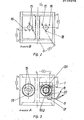
- the support structure for the laser resonator consists of a double-T profile 1 in a lightweight design, on which the optical components reflector mirror 2 with mirror mount 3, beam deflecting prism 4 with the associated beam deflecting mirrors 5 and the adjustable beam coupling optics 6 are arranged.
- the micrometer screws 7 used to adjust the beam coupling optics 6 are fastened in associated receiving bodies 8.
- this actuating medium is brought from a flow temperature TN to a defined higher temperature level TA with the aid of a flow heater 13 which can be regulated via a suitable control device 12 and is used as actuating medium for the readjustment of the optical components 2; 5; 6 used.
- the optical components each lie on a three-point support 14 made of materials with different coefficients of thermal expansion and precisely adjusted at the starting temperature TA of the actuating medium.
- the support pins 15 arranged at the end points of the tilt axis are made of steel like the associated mirror receptacle 3 and are firmly fitted into the same.
- the pin 16 opposite the tilting axis which brings about the readjustment, is made of aluminum and, in contrast, is fitted into the mirror receptacle 3 in a so-called clearance fit and is suitably secured against rotation.
- the support pins of the three-point supports 14 for the deflecting mirror 5 of the beam deflecting prism 4 likewise preferably form an equilateral triangle.
- the respective associated bases are alternatively arranged at the top and bottom parallel to the longitudinal edge of the beam deflection surfaces 17, so that the two triangles are rotated by 180 degrees.
- the aluminum pins 16 which effect the readjustment (in the illustration according to FIG. 3) are arranged in the left triangle at the bottom left and in the right triangle at the top right, so that there are two parallel tilting axes in the form shown for both mirrors 5.
- the three pins 16 (made of the same material as the deflecting prism) are in turn firmly fitted during the support pin 18 to compensate for vertical misalignment, for example - made of brass and is also fitted in a clearance fit.
- the micrometer screws 7 are used to adjust the radiation decoupling optics 6; 20, which in associated receiving bodies 8; 21 of materials with different coefficients of thermal expansion are used.
- the micrometer screws form a right angle, one leg of which runs perpendicularly and the other leg of which runs parallel to the upper edge of the double-T profile 1. Both legs serve as tilting axes for the vertical or horizontal readjustment, in particular for the vertical readjustment of the receiving body 21 for receiving the micrometer screw 20 for the vertical readjustment, which is at the end point of the vertical leg, through which the actuating medium flows.
- thermistor pairs R3.1 to R3.n on the upper cover surface 9 and corresponding thermistor pairs R4.1 to R4.n on the lower cover surface 10 are used to detect temperature gradients in the double-T profile 1 caused by climate or temperature changes of the double-T profile 1 arranged symmetrically to the carrier center axis 22 over the entire length of the profile at regular intervals.
- the series connections of all upper thermistors R3.1 to R3.n and all lower thermistors R4.1 to R4.n are connected to one another, the circuit being adjusted so that it is at an ideally adjusted laser and at the temperature TA of the actuating medium used provides the difference signal zero, while in the case of a temperature gradient, the difference between the measurement signals from the the two series connections R3 and R4 represent a measure of the temperature gradient present in each case.
- thermocouples B1 and B2 are arranged above and below the laser beam 24 with the aid of a receiving body 23 in the beam direction behind the beam coupling optics 6 and connected in series in opposite directions so that a difference signal is zero when the laser is ideally adjusted is delivered while a difference signal arises both in the case of a vertical deviation of the laser beam 24 and in the event of a change in the intensity distribution in the laser beam 24, the associated polarity of which represents a measure of the present vertical direction of misalignment and the size of which represents a measure of the degree of misalignment present.
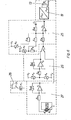
- the circuit arrangement for realizing the temperature control of the control medium used consists of a thyristor controller 19 with a downstream flow heater 13.
- the thyristor controller 19 is controlled by the PI slave controller 25, which consists of the components amplifier V5, capacitor Cl and the resistors R10 to Rl3 and which with the aid of the setting regulator R9, the temperature TA set in an ideal laser state is kept constant via the thermistor R7.
- the detection of the temperature gradient in the double-T profile 1 takes place via the circuit part 26 via the series connections of the thermistors R3.1 to R3.n or R4.1 to R4.n, the average values of which via the resistor R5 and the amplifier V2 the input of the PI slave controller 25 are guided.
- the gain factor, which causes a defined change in the temperature of the control medium used when a temperature gradient occurs, is via the counter R6 was set.
- the laser beam measurement is carried out via the circuit part 27 with the aid of the thermocouples Bl and 82 with a downstream amplifier Vi, the gain factor of which is set via the resistor R2.
- the circuit arrangement a command switch 28 , which consists of a time module Kl with an upstream selector switch Sl and an associated changeover contact Kl.1.
- the circuit is designed so that when the time module Kl is switched off, the system control takes place both in the run-in phase of the laser after starting and in the steady state via the reference variable formed from the temperature gradient, while when the time module Kl is switched on, the system control only takes place in the run-in phase from existing temperature gradient is determined and after the time set on the time module K1 with the changeover of the contact K1.1 the system control is taken over by the reference variable formed from the direct beam detection.
Landscapes
- Physics & Mathematics (AREA)
- Electromagnetism (AREA)
- Engineering & Computer Science (AREA)
- Plasma & Fusion (AREA)
- Optics & Photonics (AREA)
- Lasers (AREA)
- Piezo-Electric Or Mechanical Vibrators, Or Delay Or Filter Circuits (AREA)
- Mounting And Adjusting Of Optical Elements (AREA)
Priority Applications (1)
| Application Number | Priority Date | Filing Date | Title |
|---|---|---|---|
| AT84101953T ATE53149T1 (de) | 1983-02-24 | 1984-02-24 | Verfahren, einrichtung und schaltungsanordnung zur kompensation von betriebs- und/oder umweltbedingten dejustierungen von laserresonatoren in gefalteter anordnung. |
Applications Claiming Priority (2)
| Application Number | Priority Date | Filing Date | Title |
|---|---|---|---|
| DD83248226A DD226172A3 (de) | 1983-02-24 | 1983-02-24 | Anordnung zur stabilisierung der ausgangsparameter eines gefalteten laserresonators |
| DD248226 | 1983-02-24 |
Publications (3)
| Publication Number | Publication Date |
|---|---|
| EP0120310A2 true EP0120310A2 (fr) | 1984-10-03 |
| EP0120310A3 EP0120310A3 (en) | 1987-04-15 |
| EP0120310B1 EP0120310B1 (fr) | 1990-05-23 |
Family
ID=5545161
Family Applications (1)
| Application Number | Title | Priority Date | Filing Date |
|---|---|---|---|
| EP84101953A Expired - Lifetime EP0120310B1 (fr) | 1983-02-24 | 1984-02-24 | Méthode, procédé et circuit de compensation des défauts d'ajustement des résonateurs laser dans une structure pliée dus aux conditions de fonctionnement et/ou d'ambiance |
Country Status (8)
| Country | Link |
|---|---|
| US (1) | US4675874A (fr) |
| EP (1) | EP0120310B1 (fr) |
| JP (1) | JPS59159580A (fr) |
| AT (1) | ATE53149T1 (fr) |
| BG (1) | BG49482A1 (fr) |
| DD (1) | DD226172A3 (fr) |
| DE (1) | DE3482360D1 (fr) |
| IN (1) | IN162264B (fr) |
Families Citing this family (21)
| Publication number | Priority date | Publication date | Assignee | Title |
|---|---|---|---|---|
| US4891820A (en) * | 1985-12-19 | 1990-01-02 | Rofin-Sinar, Inc. | Fast axial flow laser circulating system |
| JPH0795605B2 (ja) * | 1987-04-03 | 1995-10-11 | 川崎重工業株式会社 | ヨウ素レ−ザ共振器 |
| US5323082A (en) * | 1989-05-03 | 1994-06-21 | Spectra Physics Lasers, Inc. | Piezoelectric actuator for planar alignment |
| US5005177A (en) * | 1989-09-27 | 1991-04-02 | Lumonics Inc. | Laser optics quality monitoring |
| US5048051A (en) * | 1990-03-02 | 1991-09-10 | Massachusetts Institute Of Technology | Optically-stabilized plano-plano optical resonators |
| US5661746A (en) * | 1995-10-17 | 1997-08-26 | Universal Laser Syatems, Inc. | Free-space gas slab laser |
| US5901167A (en) * | 1997-04-30 | 1999-05-04 | Universal Laser Systems, Inc. | Air cooled gas laser |
| US5881087A (en) * | 1997-04-30 | 1999-03-09 | Universal Laser Systems, Inc. | Gas laser tube design |
| US5867517A (en) * | 1997-04-30 | 1999-02-02 | Universal Laser Systems, Inc. | Integrated gas laser RF feed and fill apparatus and method |
| US6034977A (en) * | 1998-02-17 | 2000-03-07 | Trw Inc. | Optical path difference control system and method for solid state lasers |
| US6771437B1 (en) | 2002-02-22 | 2004-08-03 | Bae Systems Information And Electronic Systems Integration Inc. | Athermal optical bench |
| DE10314772A1 (de) * | 2003-03-31 | 2004-10-14 | Robert Bosch Gmbh | Vorrichtung zum Justieren eines optischen Spiegels |
| WO2006114832A1 (fr) * | 2005-04-06 | 2006-11-02 | Murata Manufacturing Co., Ltd. | Détecteur d’accélération |
| CN100536262C (zh) * | 2005-09-29 | 2009-09-02 | 中国科学院光电技术研究所 | 正支共焦非稳腔腔镜内自动校准装置 |
| EP2026077B1 (fr) * | 2006-06-08 | 2013-01-09 | Murata Manufacturing Co. Ltd. | Capteur d'accélération |
| KR101409110B1 (ko) * | 2010-02-25 | 2014-06-17 | 샤프 가부시키가이샤 | 표시 장치 |
| US10925805B2 (en) * | 2018-07-11 | 2021-02-23 | Bullfrog International, L.C. | Heating system for spa |
| CN109244820A (zh) * | 2018-09-25 | 2019-01-18 | 南京先进激光技术研究院 | 一种温控光学谐振腔自动稳频方法及装置 |
| US10934729B2 (en) | 2019-02-27 | 2021-03-02 | Bullfrog International, Lc | Spa cover with sensor |
| CN118263755B (zh) * | 2024-05-31 | 2024-07-26 | 厦门纽立特电子科技有限公司 | 基于分脉冲展宽光谱的凹凸腔装置 |
| CN121168086B (zh) * | 2025-11-21 | 2026-02-03 | 北京国科欣翼科技有限公司 | 一种激光线宽自适应压窄的光学谐振腔设计方法及系统 |
Family Cites Families (3)
| Publication number | Priority date | Publication date | Assignee | Title |
|---|---|---|---|---|
| US3969688A (en) * | 1975-04-14 | 1976-07-13 | United Technologies Corporation | Traveling wave unstable resonators for radial flow lasers |
| US4245195A (en) * | 1979-07-16 | 1981-01-13 | Gte Products Corporation | Laser optical resonator assembly |
| CA1139869A (fr) * | 1980-01-14 | 1983-01-18 | Henry L. Buijs | Dispositif de controle pour laser |
-
1983
- 1983-02-24 DD DD83248226A patent/DD226172A3/de not_active IP Right Cessation
- 1983-08-15 JP JP58148165A patent/JPS59159580A/ja active Granted
-
1984
- 1984-02-17 BG BG64303A patent/BG49482A1/xx unknown
- 1984-02-24 DE DE8484101953T patent/DE3482360D1/de not_active Expired - Fee Related
- 1984-02-24 US US06/583,169 patent/US4675874A/en not_active Expired - Lifetime
- 1984-02-24 AT AT84101953T patent/ATE53149T1/de not_active IP Right Cessation
- 1984-02-24 EP EP84101953A patent/EP0120310B1/fr not_active Expired - Lifetime
- 1984-03-06 IN IN160/CAL/84A patent/IN162264B/en unknown
Also Published As
| Publication number | Publication date |
|---|---|
| US4675874A (en) | 1987-06-23 |
| BG49482A1 (en) | 1991-11-15 |
| DD226172A3 (de) | 1985-08-14 |
| EP0120310A3 (en) | 1987-04-15 |
| JPS59159580A (ja) | 1984-09-10 |
| IN162264B (fr) | 1988-04-23 |
| EP0120310B1 (fr) | 1990-05-23 |
| JPH0420277B2 (fr) | 1992-04-02 |
| ATE53149T1 (de) | 1990-06-15 |
| DE3482360D1 (de) | 1990-06-28 |
Similar Documents
| Publication | Publication Date | Title |
|---|---|---|
| EP0120310B1 (fr) | Méthode, procédé et circuit de compensation des défauts d'ajustement des résonateurs laser dans une structure pliée dus aux conditions de fonctionnement et/ou d'ambiance | |
| DE60114397T2 (de) | Verfahren und vorrichtung zur korrektur von abbe fehlern | |
| DE2718807C2 (de) | Gerät zur Messung einer Dimension, insbesondere des Durchmessers, eines Objekts | |
| DE19949044A1 (de) | Vorrichtung und Feinpositionierung eines Bauteils und Koordinaten-Messmaschine mit einer Vorrichtung zur Feinpositionierung eines Bauteils | |
| DE69706819T2 (de) | Halbleiterlaserlichtquelle mit variabler Wellenlänge und mit externem Resonator | |
| DE2603423B2 (de) | Verfahren und Vorrichtung zum kantenlaufgeregelten Ausziehen des Glasbandes bei der kontinuierlichen Flachglasherstellung nach dem Floatglas-Verfahren | |
| EP0168351A1 (fr) | Générateur laser de motifs et procédé pour son emploi | |
| DE2434439A1 (de) | Multiplex-interferometer | |
| DE2202626B2 (de) | Vorrichtung zum Ausrichten von optischen Elementen | |
| DE2751415A1 (de) | Masken-photowiederholgeraet | |
| WO2012098138A1 (fr) | Dispositif de mesure doté de résistances chauffées électriquement, disposées dans des parcours de gaz | |
| DE10133582A1 (de) | Extrusions-Beschichtungs-Verfahren und -Vorrichtung | |
| DE69025202T2 (de) | Einstell- und feststellverfahren- und vorrichtung zum zusammenbauen von elementen | |
| DE3435339A1 (de) | Kapazitives hoehen(lagen)messgeraet sowie verfahren und vorrichtung zum eichen eines solchen hoehenmessgeraets | |
| WO2013072319A1 (fr) | Dilatomètre miniature pour les mesures de la dilatation thermique et de la magnétostriction à utiliser dans le cadre d'un usage multifonctionnel d'un appareil ppms | |
| DE3116214C2 (de) | Umlenkeinheit | |
| EP3479161B1 (fr) | Dispositif d'adaptation de faisceau astigmate variable et ensemble de conversion de fréquence | |
| DE2947071A1 (de) | Anordnung zur praezisionsmaterialbearbeitung mittels laserstrahlen | |
| DE3633015A1 (de) | Verfahren und anordnung zur messung des taupunktes | |
| DE3412015C2 (de) | Ringlaser | |
| DE69522463T2 (de) | Verfahren zur einstellung einer fotodetektormatrix und strahlenteilungs- und detektorstruktur für kamera mit zeilenabtastung | |
| EP0216307A2 (fr) | Dispositif mécanique pour le positionnement de deux extrémités de fibres optiques | |
| DE102014009423B4 (de) | Formklemmvorrichtung einer Spritzgussmaschine mit Temperaturanpassung | |
| DE112010005364T5 (de) | Parallelschiebevorrichtung mit einer Druckluftlinearführung, Steuerverfahren dafür und Messvorrichtung, welche diese verwendet | |
| AT394271B (de) | Messsystem zur messung der laengs- und querausdehnung eines werkstuecks |
Legal Events
| Date | Code | Title | Description |
|---|---|---|---|
| PUAI | Public reference made under article 153(3) epc to a published international application that has entered the european phase |
Free format text: ORIGINAL CODE: 0009012 |
|
| AK | Designated contracting states |
Designated state(s): AT BE CH DE FR GB IT LI NL SE |
|
| PUAL | Search report despatched |
Free format text: ORIGINAL CODE: 0009013 |
|
| AK | Designated contracting states |
Kind code of ref document: A3 Designated state(s): AT BE CH DE FR GB IT LI NL SE |
|
| 17P | Request for examination filed |
Effective date: 19870511 |
|
| 17Q | First examination report despatched |
Effective date: 19890606 |
|
| ITF | It: translation for a ep patent filed | ||
| GRAA | (expected) grant |
Free format text: ORIGINAL CODE: 0009210 |
|
| AK | Designated contracting states |
Kind code of ref document: B1 Designated state(s): AT BE CH DE FR GB IT LI NL SE |
|
| REF | Corresponds to: |
Ref document number: 53149 Country of ref document: AT Date of ref document: 19900615 Kind code of ref document: T |
|
| REF | Corresponds to: |
Ref document number: 3482360 Country of ref document: DE Date of ref document: 19900628 |
|
| ET | Fr: translation filed | ||
| GBT | Gb: translation of ep patent filed (gb section 77(6)(a)/1977) | ||
| PLBE | No opposition filed within time limit |
Free format text: ORIGINAL CODE: 0009261 |
|
| STAA | Information on the status of an ep patent application or granted ep patent |
Free format text: STATUS: NO OPPOSITION FILED WITHIN TIME LIMIT |
|
| 26N | No opposition filed | ||
| PGFP | Annual fee paid to national office [announced via postgrant information from national office to epo] |
Ref country code: SE Payment date: 19950111 Year of fee payment: 12 |
|
| EAL | Se: european patent in force in sweden |
Ref document number: 84101953.2 |
|
| PGFP | Annual fee paid to national office [announced via postgrant information from national office to epo] |
Ref country code: AT Payment date: 19950131 Year of fee payment: 12 |
|
| PGFP | Annual fee paid to national office [announced via postgrant information from national office to epo] |
Ref country code: BE Payment date: 19950202 Year of fee payment: 12 |
|
| PGFP | Annual fee paid to national office [announced via postgrant information from national office to epo] |
Ref country code: NL Payment date: 19950228 Year of fee payment: 12 |
|
| PG25 | Lapsed in a contracting state [announced via postgrant information from national office to epo] |
Ref country code: AT Effective date: 19960224 |
|
| PG25 | Lapsed in a contracting state [announced via postgrant information from national office to epo] |
Ref country code: SE Effective date: 19960225 |
|
| PG25 | Lapsed in a contracting state [announced via postgrant information from national office to epo] |
Ref country code: BE Effective date: 19960228 |
|
| BERE | Be: lapsed |
Owner name: VEB KOMBINAT FEINMECHANISCHE WERKE HALLE Effective date: 19960228 |
|
| PG25 | Lapsed in a contracting state [announced via postgrant information from national office to epo] |
Ref country code: NL Effective date: 19960901 |
|
| NLV4 | Nl: lapsed or anulled due to non-payment of the annual fee |
Effective date: 19960901 |
|
| PGFP | Annual fee paid to national office [announced via postgrant information from national office to epo] |
Ref country code: GB Payment date: 19990217 Year of fee payment: 16 |
|
| PGFP | Annual fee paid to national office [announced via postgrant information from national office to epo] |
Ref country code: FR Payment date: 19990323 Year of fee payment: 16 |
|
| PGFP | Annual fee paid to national office [announced via postgrant information from national office to epo] |
Ref country code: CH Payment date: 19990329 Year of fee payment: 16 |
|
| PGFP | Annual fee paid to national office [announced via postgrant information from national office to epo] |
Ref country code: DE Payment date: 19990408 Year of fee payment: 16 |
|
| PG25 | Lapsed in a contracting state [announced via postgrant information from national office to epo] |
Ref country code: GB Free format text: LAPSE BECAUSE OF NON-PAYMENT OF DUE FEES Effective date: 20000224 |
|
| PG25 | Lapsed in a contracting state [announced via postgrant information from national office to epo] |
Ref country code: LI Free format text: LAPSE BECAUSE OF NON-PAYMENT OF DUE FEES Effective date: 20000229 Ref country code: CH Free format text: LAPSE BECAUSE OF NON-PAYMENT OF DUE FEES Effective date: 20000229 |
|
| GBPC | Gb: european patent ceased through non-payment of renewal fee |
Effective date: 20000224 |
|
| REG | Reference to a national code |
Ref country code: CH Ref legal event code: PL |
|
| PG25 | Lapsed in a contracting state [announced via postgrant information from national office to epo] |
Ref country code: FR Free format text: LAPSE BECAUSE OF NON-PAYMENT OF DUE FEES Effective date: 20001031 |
|
| PG25 | Lapsed in a contracting state [announced via postgrant information from national office to epo] |
Ref country code: DE Free format text: LAPSE BECAUSE OF NON-PAYMENT OF DUE FEES Effective date: 20001201 |
|
| REG | Reference to a national code |
Ref country code: FR Ref legal event code: ST |