EP0120354A2 - Appareil de massage par bouillonnement d'air - Google Patents
Appareil de massage par bouillonnement d'air Download PDFInfo
- Publication number
- EP0120354A2 EP0120354A2 EP84102377A EP84102377A EP0120354A2 EP 0120354 A2 EP0120354 A2 EP 0120354A2 EP 84102377 A EP84102377 A EP 84102377A EP 84102377 A EP84102377 A EP 84102377A EP 0120354 A2 EP0120354 A2 EP 0120354A2
- Authority
- EP
- European Patent Office
- Prior art keywords
- housing
- control device
- air bubble
- recess
- massager according
- Prior art date
- Legal status (The legal status is an assumption and is not a legal conclusion. Google has not performed a legal analysis and makes no representation as to the accuracy of the status listed.)
- Withdrawn
Links
Images

Classifications
-
- A—HUMAN NECESSITIES
- A61—MEDICAL OR VETERINARY SCIENCE; HYGIENE
- A61H—PHYSICAL THERAPY APPARATUS, e.g. DEVICES FOR LOCATING OR STIMULATING REFLEX POINTS IN THE BODY; ARTIFICIAL RESPIRATION; MASSAGE; BATHING DEVICES FOR SPECIAL THERAPEUTIC OR HYGIENIC PURPOSES OR SPECIFIC PARTS OF THE BODY
- A61H33/00—Bathing devices for special therapeutic or hygienic purposes
- A61H33/02—Bathing devices for use with gas-containing liquid, or liquid in which gas is led or generated, e.g. carbon dioxide baths
- A61H33/028—Means for producing a flow of gas, e.g. blowers, compressors
-
- A—HUMAN NECESSITIES
- A61—MEDICAL OR VETERINARY SCIENCE; HYGIENE
- A61H—PHYSICAL THERAPY APPARATUS, e.g. DEVICES FOR LOCATING OR STIMULATING REFLEX POINTS IN THE BODY; ARTIFICIAL RESPIRATION; MASSAGE; BATHING DEVICES FOR SPECIAL THERAPEUTIC OR HYGIENIC PURPOSES OR SPECIFIC PARTS OF THE BODY
- A61H33/00—Bathing devices for special therapeutic or hygienic purposes
- A61H33/60—Components specifically designed for the therapeutic baths of groups A61H33/00
Definitions
- the invention relates to an air bubble massager with a seat which can be used as a seat and which can be closed by means of a cover and which accommodates the collapsible bubble mat, the air hose and the control unit with the blower, the heater and the adjusting elements.
- An air bubble massager of this type is known from US-PS 32 67 936 and has the advantage that the bubble mat and the air hose are stored next to the control unit when not in use.
- the housing which can be used as a seat, also has space in every small bathroom and protects all parts of the air bubble massager.
- a lower and an upper receiving space is divided into the housing by means of a horizontal partition.
- the lower receiving space accommodates - the blower and the other functional units.
- the adjustment devices are. arranged in the partition and in the upper receiving space, which is closed by the lid, the disassembled bubbling grate and the air hose can be inserted.
- This known air bubble massager is not easy to use, since the setting members are only accessible when the lid is open and, moreover, are much lower than the upper edge of the housing. This is a serious disadvantage especially for a user lying in the bathtub, since he has to stand up in order to be able to access the adjusting elements at all.
- this structure of an air bubble massage device does not meet the safety regulations and requirements placed on such devices the construction also requires considerable installation work in the housing.
- the control unit is only accessible when dismantled and is difficult to test on its own.
- the housing has a recess in the area of at least one vertical side wall, in which the control unit designed as a separate structural unit is set, and in that the setting members of the control unit are arranged in the upper region of a visible wall of the control unit.
- the recess in the housing creates a parking space for the control unit designed as a separate structural unit.
- the control unit can therefore be prefabricated according to safety-related conditions and checked for itself before it is placed in the space provided in the housing. In addition to the seating, the rest of the housing also offers enough space to accommodate the collapsible bubbling grate and the air hose.
- one embodiment provides that the housing is cuboid and that the recess is arranged in a longitudinal side wall of the housing.
- the design is preferably such that the control unit set in the recess of the housing is flush with the side walls of the housing that are facing.
- a simple and fully sufficient receptacle for the control device is created according to one embodiment in that the recess which is open to the sides and to the front is delimited at the bottom by a base plate and at the top by a projecting housing part.
- a further embodiment provides that the control device is fixed in the recess in the housing. The easiest way to do this is to screw the control unit onto the base plate of the housing.
- control unit is cuboid-shaped and runs out toward the upper side in a pedestal-like attachment part, that the e insehbare front is -des attachment part at an obtuse angle to the adjoining front face of the control unit and is designed as a control panel with the setting members and that the projecting housing part of the housing is adapted to the contour of the top part of the control unit.
- An embodiment is advantageous, which is characterized in that the plug receptacle for connecting the air hose to the compressed air outlet of the blower is also arranged in the control panel. The large side surfaces of the control unit then remain closed.
- control device The construction of the control device is facilitated in that the control panel is connected to the attachment part of the control device as a separate building board with built-in adjustment elements.
- the use as a seat is improved in that the area of the upper side of the housing facing the control unit is designed as a seat plate which is firmly connected to the housing and passes over a rounded or inclined transition section into the front of the projecting housing part and the control unit and that remaining area of the top is covered by the lid.
- the seat plate is then an integral part of the housing, which cannot unintentionally detach, which significantly increases safety.
- the cover is sufficient to allow access to the housing receiving space. This access is facilitated in that the housing facing the cover is designed as a plug-in receptacle into which the cover provided with plug-in edges can be inserted. The cover only needs to be removed from the housing, but is sufficiently secured and secured to the housing in the closed position.
- the design of the seat plate is' carried out so that the seat plate consists of individual strips that are connected to the housing and cover the open top of the housing in the region of the seat plate. Wooden strips can be used.
- the manufacture of the housing is cheaper because the base plate, the projecting housing part and the transition section are integrally formed on the housing and that the housing is open towards the control unit in the area of the contact surfaces.
- the recess for the control device extends only over the upper part of a side wall of the housing, that the recess is closed at the bottom by means of an intermediate plate or the like, and that between the intermediate plate and the Base plate is formed a further recess for setting a small bathtub.
- the small bathtub also has a place in the housing when not in use and is placed cleanly.
- An embodiment is preferred which is characterized in that the set small bathtub is flush with the adjoining side walls of the control unit and the housing.
- the removal of the small bathtub from the recess in the housing is facilitated in that two opposite side walls of the small bathtub in the upper area with handle elements, e.g. Handle openings are provided.
- the control device 10 represents a separate structural unit which can be prefabricated and tested on its own.
- the control unit housing accommodates the blower, the heater and the other functional units that are used for the generation of compressed air and the control of the compressed air delivery required are.
- This unit is subject to special safety regulations because it accepts live parts.
- the control device 10 is cuboid in the embodiment and has a closed lower housing part that complies with the safety regulations.
- the desk-like attachment part 11 is placed on the cuboid housing bottom part and is closed towards the front with the building board used as the control panel 12. This building board accommodates the setting members 13 to 15 and also the connecting piece 16 for the air hose, which connects the bubble mat to the blower.
- the connecting piece 16 leads in the control unit 10 to the compressed air outlet of the fan.
- the control panel 12 is slightly inclined to the rear so that it includes an obtuse angle to the front of the control unit 10. The control panel 12 is therefore easier to see from above and the adjustment members 13 to 15 are easier to use when the device is placed next to a bathtub.
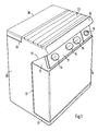
- the housing 20 which can be used as a seat is also essentially cuboid, the front front having a recess 27 which is delimited at the bottom by the base plate 21 and at the top by the projecting housing part 22. If the control device 10 is set in this recess 27, then the side walls of the control device 10 are flush with the side walls of the housing 20.
- the projecting housing part 22 is adapted to the contour of the desk-like attachment part 11 of the control device 10 and slightly projects beyond the control panel 12.
- the housing part 22 merges into the seat plate 23 via the inclined transition section 24 and, like the base plate 21, is preferably in one piece with the housing 20 connected.
- the seat plate 23 can be formed from individual strips which, following the transition section, cover part of the open top of the housing 20 and are firmly connected to the latter. The rest of the The open top of the housing 20 is closed by means of the cover 26, which is provided with plug-in edges and is inserted into the plug-in receptacle 25 formed on the top of the housing 20 and is held sufficiently therein.
- control device 10 can also be fixed in the recess 27. For this purpose, it is simply screwed to the base plate 21 of the housing 20.
- the housing 20 can only consist of the side walls, the rear wall and the base plate 21, since the control unit completes the receptacle for the folded bubble mat and the air hose in the housing 20. As a result, the housing 20 is significantly cheaper.
- the control device 10 can also be made smaller, so that it can be accommodated in a smaller recess 27 in the front of the housing 20.
- the desk-like structure 11 with the control panel 12 remains unchanged, as does the projecting housing part 22 with the transition section 24.
- the recess 27 is placed in the upper region of the front face, so that the adjusting members 13 to 15 are again clearly visible and easily accessible.
- a further recess 29 is delimited below the recess 27 and is delimited by the base plate 21 and the intermediate plate 28.
- the control unit 10 can be parked on the intermediate plate 28 and held or fixed thereon.
- the small bathtub 30 is inserted into the recess 29 and is flush with the adjacent side walls of the control unit 10 and the housing 20.
- the small bathtub 30 can be designed and used as an arm or foot bathtub.
- the bottom plate 21 can hold the small bathtub 30 in connection with the adjacent side walls of the housing 20. So that the small bathtub 30 can be easily removed from the recess 29, handle elements, for example handle openings 31, are provided in the upper regions of two opposite side walls of the small bathtub.
- the housing 20 with the set control device 10 and the set small bath tub 30 carries rollers on the underside of the base plate 21 and is therefore designed to be mobile.
Landscapes
- Health & Medical Sciences (AREA)
- Public Health (AREA)
- Epidemiology (AREA)
- Pain & Pain Management (AREA)
- Physical Education & Sports Medicine (AREA)
- Rehabilitation Therapy (AREA)
- Life Sciences & Earth Sciences (AREA)
- Animal Behavior & Ethology (AREA)
- General Health & Medical Sciences (AREA)
- Veterinary Medicine (AREA)
- Percussion Or Vibration Massage (AREA)
- Devices For Medical Bathing And Washing (AREA)
Applications Claiming Priority (2)
| Application Number | Priority Date | Filing Date | Title |
|---|---|---|---|
| DE3311103 | 1983-03-26 | ||
| DE3311103A DE3311103C2 (de) | 1983-03-26 | 1983-03-26 | Luftsprudelmassagegerät |
Publications (2)
| Publication Number | Publication Date |
|---|---|
| EP0120354A2 true EP0120354A2 (fr) | 1984-10-03 |
| EP0120354A3 EP0120354A3 (fr) | 1985-01-09 |
Family
ID=6194776
Family Applications (1)
| Application Number | Title | Priority Date | Filing Date |
|---|---|---|---|
| EP84102377A Withdrawn EP0120354A3 (fr) | 1983-03-26 | 1984-03-06 | Appareil de massage par bouillonnement d'air |
Country Status (3)
| Country | Link |
|---|---|
| US (1) | US4566443A (fr) |
| EP (1) | EP0120354A3 (fr) |
| DE (1) | DE3311103C2 (fr) |
Cited By (3)
| Publication number | Priority date | Publication date | Assignee | Title |
|---|---|---|---|---|
| DE8907568U1 (de) * | 1989-06-21 | 1989-11-02 | Mayer, Herbert, 8940 Memmingen | Luftsprudelvorrichtung mit Fußbadewanne |
| EP0355299A3 (fr) * | 1988-06-30 | 1991-03-20 | Heddernheimer Metallwarenfabrik GmbH | Dispositif d'hydrothérapie |
| DE4030556C1 (en) * | 1990-09-27 | 1992-01-02 | Metronic Electronic Gmbh, 7210 Rottweil, De | Air massage machine - has control housing with collapsible air ducts and jet openings |
Families Citing this family (11)
| Publication number | Priority date | Publication date | Assignee | Title |
|---|---|---|---|---|
| USD305688S (en) | 1987-06-26 | 1990-01-23 | Associated Mills Inc. | Control unit for a bubbling bath device |
| US4872224A (en) * | 1988-02-16 | 1989-10-10 | Grimes Fred D | Bathtub apparatus |
| DE19907404C2 (de) * | 1998-04-11 | 2001-02-01 | W & W Frenkel Gmbh & Co Kg | Wellness-Oase in Säulenform |
| WO2015010058A2 (fr) | 2013-07-18 | 2015-01-22 | Intex Recreation Corp. | Spa gonflable |
| CN103600502A (zh) | 2013-11-25 | 2014-02-26 | 明达实业(厦门)有限公司 | 一种充气产品熔着工艺 |
| EP4222329B1 (fr) | 2020-09-29 | 2026-04-15 | Intex Marketing Ltd. | Unité de passage d'air, système de passage d'air, corps de bassin et bassin de massage |
| EP4650633A3 (fr) | 2021-07-15 | 2026-02-18 | Intex Marketing Ltd. | Un système d'air d'une piscine de massage, comprenant une pompe à air et une unité d'air |
| CN216045610U (zh) | 2021-07-15 | 2022-03-15 | 明达实业(厦门)有限公司 | 带控制阀的按摩水池气路结构 |
| CN216009650U (zh) | 2021-07-15 | 2022-03-11 | 明达实业(厦门)有限公司 | 按摩水池接气管路装置、按摩水池池体及按摩水池 |
| CN216042922U (zh) | 2021-07-15 | 2022-03-15 | 明达实业(厦门)有限公司 | Spa水池带补偿功能的气路结构及spa水池 |
| US20260022882A1 (en) * | 2024-07-22 | 2026-01-22 | Matthew Philip Davidson | Portable water-cooled air conditioner with a dedicated storage compartment for a hose kit |
Family Cites Families (9)
| Publication number | Priority date | Publication date | Assignee | Title |
|---|---|---|---|---|
| US1409330A (en) * | 1920-12-18 | 1922-03-14 | Anna B Aper | Nursery bath cabinet |
| US3267936A (en) * | 1963-11-01 | 1966-08-23 | Osborn Engineering Corp | Hydrotherapy apparatus |
| US3280458A (en) * | 1963-12-19 | 1966-10-25 | Dentists Supply Co | Dental equipment stand |
| US3597033A (en) * | 1968-12-20 | 1971-08-03 | American Hospital Supply Corp | Mobile dental console |
| DE7142241U (de) * | 1971-11-09 | 1972-02-17 | Baumann L | Mit einem drucklufterzeuger insbesondere geblaese betriebenes unterwasser-luftsprudelgeraet fuer badewannen u.dgl. |
| US3845759A (en) * | 1973-08-24 | 1974-11-05 | J Miklovic | Whirlpool bath |
| CH596833A5 (fr) * | 1975-09-25 | 1978-03-31 | Creativ Patentanstalt | |
| US4262374A (en) * | 1978-12-05 | 1981-04-21 | Nikki Co., Ltd. | Bubble wash unit |
| DE3202862C2 (de) * | 1982-01-29 | 1984-04-12 | Metronic Electronic GmbH, 7210 Rottweil | Luftsprudelmassagegerät |
-
1983
- 1983-03-26 DE DE3311103A patent/DE3311103C2/de not_active Expired
-
1984
- 1984-02-28 US US06/584,513 patent/US4566443A/en not_active Expired - Fee Related
- 1984-03-06 EP EP84102377A patent/EP0120354A3/fr not_active Withdrawn
Cited By (3)
| Publication number | Priority date | Publication date | Assignee | Title |
|---|---|---|---|---|
| EP0355299A3 (fr) * | 1988-06-30 | 1991-03-20 | Heddernheimer Metallwarenfabrik GmbH | Dispositif d'hydrothérapie |
| DE8907568U1 (de) * | 1989-06-21 | 1989-11-02 | Mayer, Herbert, 8940 Memmingen | Luftsprudelvorrichtung mit Fußbadewanne |
| DE4030556C1 (en) * | 1990-09-27 | 1992-01-02 | Metronic Electronic Gmbh, 7210 Rottweil, De | Air massage machine - has control housing with collapsible air ducts and jet openings |
Also Published As
| Publication number | Publication date |
|---|---|
| DE3311103C2 (de) | 1985-12-12 |
| EP0120354A3 (fr) | 1985-01-09 |
| US4566443A (en) | 1986-01-28 |
| DE3311103A1 (de) | 1984-10-04 |
Similar Documents
| Publication | Publication Date | Title |
|---|---|---|
| DE69202315T2 (de) | Sanitärvorrichtung wie Waschbecken, Bidet oder dergleichen. | |
| EP0120354A2 (fr) | Appareil de massage par bouillonnement d'air | |
| EP0379497B1 (fr) | Logement destine a recevoir des accessoires d'hygiene buccale et dentaire | |
| DE69023237T2 (de) | Zusammenfaltbare bronzierungskabine. | |
| DE4106213A1 (de) | Halter fuer ein reibeisen oder dergleichen | |
| DE19901350A1 (de) | Scharnierbaugruppe für ein Gehäuse | |
| DE1088551B (de) | Als Standmikrotelefon ausgebildeter Fernsprechapparat | |
| DE4319407A1 (de) | Mikrocomputer mit einem Rechnergehäuse, einem Monitor und einer Tastatur | |
| DE3202862C2 (de) | Luftsprudelmassagegerät | |
| EP0076906A1 (fr) | Dispositif de support de douche | |
| DE8309070U1 (de) | Luftsprudelmassagegeraet | |
| DE3822176A1 (de) | Stroemungs-behandlungsgeraet zur behandlung des menschlichen koerpers | |
| DE7719844U1 (de) | Schreibtisch mit einem kabelkanal | |
| DE3112718C2 (de) | Bausatz für Schalt- und/oder Steuerschrank | |
| DE3881968T2 (de) | Somatisches musikalisches aussetzungssystem. | |
| DE3803814C2 (fr) | ||
| DE10235776A1 (de) | Küchenmodulsystem | |
| DE4005137C2 (fr) | ||
| DE4030556C2 (de) | Luftsprudelmassagegerät | |
| DE29904616U1 (de) | Trainingsgerät | |
| EP0313933B1 (fr) | Dispositif de massage | |
| DE8702390U1 (de) | Badewanne | |
| AT939U1 (de) | Einrichtung für die fusssohlenreflexzonen-massage | |
| DE8402653U1 (de) | Fussmassagegeraet | |
| DE2746212C3 (de) | Toiletteschrank |
Legal Events
| Date | Code | Title | Description |
|---|---|---|---|
| PUAI | Public reference made under article 153(3) epc to a published international application that has entered the european phase |
Free format text: ORIGINAL CODE: 0009012 |
|
| AK | Designated contracting states |
Designated state(s): AT BE CH FR GB IT LI LU NL SE |
|
| PUAL | Search report despatched |
Free format text: ORIGINAL CODE: 0009013 |
|
| AK | Designated contracting states |
Designated state(s): AT BE CH FR GB IT LI LU NL SE |
|
| 17P | Request for examination filed |
Effective date: 19841116 |
|
| STAA | Information on the status of an ep patent application or granted ep patent |
Free format text: STATUS: THE APPLICATION HAS BEEN WITHDRAWN |
|
| 18W | Application withdrawn |
Withdrawal date: 19860705 |
|
| RIN1 | Information on inventor provided before grant (corrected) |
Inventor name: BUCHER, HEINZ |