EP0120367B1 - Elément de construction pour réaliser une enceinte rectangulaire - Google Patents
Elément de construction pour réaliser une enceinte rectangulaire Download PDFInfo
- Publication number
- EP0120367B1 EP0120367B1 EP84102493A EP84102493A EP0120367B1 EP 0120367 B1 EP0120367 B1 EP 0120367B1 EP 84102493 A EP84102493 A EP 84102493A EP 84102493 A EP84102493 A EP 84102493A EP 0120367 B1 EP0120367 B1 EP 0120367B1
- Authority
- EP
- European Patent Office
- Prior art keywords
- shell portion
- shell
- profiling
- case
- glued
- Prior art date
- Legal status (The legal status is an assumption and is not a legal conclusion. Google has not performed a legal analysis and makes no representation as to the accuracy of the status listed.)
- Expired - Lifetime
Links
- 238000010276 construction Methods 0.000 title claims 2
- 239000004033 plastic Substances 0.000 claims description 6
- 229920003023 plastic Polymers 0.000 claims description 6
- 239000000112 cooling gas Substances 0.000 claims description 4
- 239000012815 thermoplastic material Substances 0.000 claims description 2
- 238000000465 moulding Methods 0.000 description 6
- 238000004519 manufacturing process Methods 0.000 description 4
- 238000000034 method Methods 0.000 description 4
- 238000000926 separation method Methods 0.000 description 4
- 238000001816 cooling Methods 0.000 description 3
- 229920001169 thermoplastic Polymers 0.000 description 2
- 239000004604 Blowing Agent Substances 0.000 description 1
- 239000004793 Polystyrene Substances 0.000 description 1
- 239000000853 adhesive Substances 0.000 description 1
- 238000004026 adhesive bonding Methods 0.000 description 1
- 230000001070 adhesive effect Effects 0.000 description 1
- 238000005187 foaming Methods 0.000 description 1
- 238000001746 injection moulding Methods 0.000 description 1
- 238000005304 joining Methods 0.000 description 1
- 238000005192 partition Methods 0.000 description 1
- 230000002093 peripheral effect Effects 0.000 description 1
- 229920002223 polystyrene Polymers 0.000 description 1
- 229920002635 polyurethane Polymers 0.000 description 1
- 239000004814 polyurethane Substances 0.000 description 1
- 230000001681 protective effect Effects 0.000 description 1
- 239000007921 spray Substances 0.000 description 1
- 238000003860 storage Methods 0.000 description 1
- 239000004416 thermosoftening plastic Substances 0.000 description 1
Images


Classifications
-
- A—HUMAN NECESSITIES
- A47—FURNITURE; DOMESTIC ARTICLES OR APPLIANCES; COFFEE MILLS; SPICE MILLS; SUCTION CLEANERS IN GENERAL
- A47B—TABLES; DESKS; OFFICE FURNITURE; CABINETS; DRAWERS; GENERAL DETAILS OF FURNITURE
- A47B31/00—Service or tea tables, trolleys, or wagons
- A47B31/06—Service or tea tables, trolleys, or wagons adapted to the use in vehicles
-
- B—PERFORMING OPERATIONS; TRANSPORTING
- B65—CONVEYING; PACKING; STORING; HANDLING THIN OR FILAMENTARY MATERIAL
- B65D—CONTAINERS FOR STORAGE OR TRANSPORT OF ARTICLES OR MATERIALS, e.g. BAGS, BARRELS, BOTTLES, BOXES, CANS, CARTONS, CRATES, DRUMS, JARS, TANKS, HOPPERS, FORWARDING CONTAINERS; ACCESSORIES, CLOSURES, OR FITTINGS THEREFOR; PACKAGING ELEMENTS; PACKAGES
- B65D11/00—Containers having bodies formed by interconnecting or uniting two or more rigid, or substantially rigid, components made wholly or mainly of plastics material
- B65D11/10—Containers having bodies formed by interconnecting or uniting two or more rigid, or substantially rigid, components made wholly or mainly of plastics material of polygonal cross-section and all parts being permanently connected to each other
Definitions
- the invention relates to a component for producing a cuboid housing made of plastic for a serving trolley, in particular a serving trolley for aircraft.
- housings and container parts in a suitable tool, e.g. to be made from plastics such as polystyrene or polyurethane using the foaming technique or the spray technique. Furniture and device parts, as well as housings for serving trolleys, are manufactured in a mold using injection molding machines. The costs of the molding tools play a not inconsiderable effort. If several sizes of one device type are to be manufactured, corresponding different molding tools must be available.
- US-A-3905 668 shows a component for producing a cuboid housing, which comprises half the housing cover, half the housing base, half of the two side walls and a complete end wall.
- thermoplastic plastic described in DE-B-1055 802 is not suitable for large components, such as the housing of a serving trolley.
- the invention has for its object to manufacture the container for a serving trolley, in particular a serving trolley for airplanes - from plastic with little outlay on tooling costs and yet to maintain the required strength.
- the housing consists of two identical shell parts, whereby the uniform shell part is designed so that on the one hand it can be connected to a body with the same shell part, but on the other hand it is also possible to halve one shell part and the two parts obtained into one Join the half-size body.
- the necessary strength of the connection is made possible by the fact that the large areas to be joined together have a profiling which, on one half of the shell, is negatively counter to the profiling of the other halves of the shell.
- the housing 1 consists of the side wall 1, half the housing cover 2 and half the housing base 3. In addition, half partitions for the upper drawer 4 and a central stiffening wall 5th be provided.
- the housing cover 2 is provided with a raised peripheral edge 6, so that a secure storage space is created. Lateral support and guide strips 7 for trays to be inserted as well as cooling channels 8 for the cooling gas flowing out of the upper cooling compartment are formed in the side wall 1.
- Such a component, which forms a housing half is made of a thermoplastic with very high impact strength according to the so-called TSG process. In this special process, the thermoplastic material to be sprayed is additionally mixed with a blowing agent for better mold filling and surface quality.
- the plastic is completely colored with the desired color. This creates a practically indestructible container even in rough use, which still has its external appearance even after a long time.
- Two such shell parts produced in the same molding tool are permanently bonded to one another to form a heavy-duty housing by appropriately designing the connection points by joining them in mirror image.
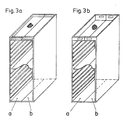
- 3a and 3b show this in two examples in which the ceiling area is designed differently.
- An identical part b is added to part a in mirror image.
- the gluing point of the abutting transverse walls can be formed according to FIG. 2.
- the Z-shaped profile ensures that the two shell parts fit together precisely because their tips slide into a counter-groove.
- the component according to the invention is also symmetrically divided into two equal halves in relation to a central plane E (indicated by a line) that runs through the housing cover, side wall and housing base. If the shell part is separated along this plane, two parts are obtained which can likewise be joined together to form a housing, albeit of half the size, as illustrated in FIG. 4. The later separation can be facilitated by inserting strips in the area of the separation point for the molding tool.
- connection points (Fig. 2) is formed on one half of the shell part negatively congruent to the profile of the other half of the shell part so that the shell parts, be it the whole or the halved shell parts can be put together in mirror image.
- the side cooling gas channels 8 starting from the upper cooling compartment are arranged in the interior of the side wall 1 such that after the separation of the shell divider at least one cooling gas channel 8 remains at both ends of the shell part halves, as indicated in FIG. 1.
Landscapes
- Engineering & Computer Science (AREA)
- Mechanical Engineering (AREA)
- Moulds For Moulding Plastics Or The Like (AREA)
- Injection Moulding Of Plastics Or The Like (AREA)
Claims (5)
- Composant pour la fabrication d'une caisse en plastique sous la forme d'un parallélépipède pour une charrette de service, particulièrement une charrette de service pour des avions,
caractérisé en ce quea) ledit composant se compose d'une partie d'enveloppe formant l'une paroi latérale (1) et la moitié du plafond (2) et du fonds (3) de la moitié de la caisse, ladite partie d'enveloppe étant moulée d'une seule pièce d'une matière thermoplastique dans un moule,b) ladite partie d'enveloppe est divisée symétriquement par rapport à un plan de symétrie (E) central s'étendant à travers du plafond (2), de la paroi latérale (1) et du fond (3) de la caisse en deux moitiés identiques de la partie d'enveloppe,c) les surfaces d'about des faces des moitiés du plafond et du fond de la caisse à coller lors de l'assemblage de deux parties d'enveloppe comportant un profilage étant négativement congru sur une moitié de la partie d'enveloppe par rapport au profilage sur l'autre moitié de la partie d'enveloppe. - Composant selon la revendication 1,
caractérisé en ce que le profilage des faces des deux parties d'enveloppe est en forme d'U. - Composant selon les revendications 1 et 2,
caractérisé en ce que le profilage en forme d'U des faces à coller est collé d'une telle manière, que le bout d'une partie d'enveloppe glisse dans une contre-rainure de l'autre partie d'enveloppe. - Composant selon une ou plusieurs des revendications 1 à 3,
caractérisé en ce que parallèlement au plafond (2) de la caisse s'étend au moins une paroi transversale (4, 5). - Composant selon une des revendications 1 à 4,
caractérisé en ce que la paroi latérale (1) de chaque moitié de la partie d'enveloppe est pourvue d'au moins deux canaux de gaz de refroidissement (8) verticaux.
Applications Claiming Priority (2)
| Application Number | Priority Date | Filing Date | Title |
|---|---|---|---|
| DE8309164U | 1983-03-28 | ||
| DE19838309164U DE8309164U1 (de) | 1983-03-28 | 1983-03-28 | Bauelement zur herstellung eines quaderfoermigen gehaeuses |
Publications (3)
| Publication Number | Publication Date |
|---|---|
| EP0120367A2 EP0120367A2 (fr) | 1984-10-03 |
| EP0120367A3 EP0120367A3 (en) | 1988-07-20 |
| EP0120367B1 true EP0120367B1 (fr) | 1991-09-11 |
Family
ID=6751698
Family Applications (1)
| Application Number | Title | Priority Date | Filing Date |
|---|---|---|---|
| EP84102493A Expired - Lifetime EP0120367B1 (fr) | 1983-03-28 | 1984-03-08 | Elément de construction pour réaliser une enceinte rectangulaire |
Country Status (3)
| Country | Link |
|---|---|
| US (1) | US4616754A (fr) |
| EP (1) | EP0120367B1 (fr) |
| DE (2) | DE8309164U1 (fr) |
Families Citing this family (13)
| Publication number | Priority date | Publication date | Assignee | Title |
|---|---|---|---|---|
| US4848608A (en) * | 1987-10-09 | 1989-07-18 | Grumman Aerospace Corporation | Expandable racking system for trays or the like |
| US5016948A (en) * | 1989-02-02 | 1991-05-21 | Intermetro Industries Corporation | Modular utility cart |
| US4910866A (en) * | 1989-02-21 | 1990-03-27 | Micron Technology, Inc. | Method of manufacturing a series of leadframe strip carriers having fixed external dimensions and varied internal dimensions using a common mold |
| USD345547S (en) | 1992-03-03 | 1994-03-29 | International Business Machines Corporation | Rack and cover system |
| US6419098B1 (en) * | 1995-02-10 | 2002-07-16 | Donald M. Hall | Nestable and/or liftable rack |
| US7419063B1 (en) | 1996-04-26 | 2008-09-02 | M & E Manufacturing Company, Inc. | Nestable and liftable oven rack |
| US20020162813A1 (en) * | 1997-04-25 | 2002-11-07 | Hall Donald M. | V-shaped nestable tray rack |
| US6102216A (en) * | 1999-03-11 | 2000-08-15 | Frank; Monty S | Attire organizer |
| GB9911004D0 (en) * | 1999-05-13 | 1999-07-14 | Stalley Francis E | Plane clearing trolley (P.E.T.) |
| US20040118730A1 (en) * | 2002-11-05 | 2004-06-24 | Rynel, Inc. | Trays for growth plugs, and methods of producing them |
| NL2011754C2 (en) * | 2013-11-07 | 2015-05-11 | Gils Stephanus Johannes Van | Galley container. |
| ES2739682T3 (es) * | 2014-04-10 | 2020-02-03 | Gratzup Corp | Contenedor para esterilizar objetos y sistema de esterilización que comprende dicho contenedor |
| US10034806B1 (en) * | 2017-05-24 | 2018-07-31 | Samuel Greenhalgh, Sr. | Over-bed table organizer |
Family Cites Families (13)
| Publication number | Priority date | Publication date | Assignee | Title |
|---|---|---|---|---|
| US785591A (en) * | 1904-11-22 | 1905-03-21 | John Gabriel Conez | Cabinet for pies. |
| US1342269A (en) * | 1919-10-08 | 1920-06-01 | Irving N Stewart | Portable wardrobe |
| DE1055802B (de) * | 1956-06-28 | 1959-04-23 | Bayerische Fichtenpechsiederei | Verfahren zum Herstellen von aufstellbaren Behaeltern aus einem organischen thermoplastischen Kunststoff aus zwei zusammengehoerigen Behaelterhaelften |
| US2930487A (en) * | 1957-05-15 | 1960-03-29 | Dart Mfg Company | Wall mountable shelf unit |
| US3298763A (en) * | 1965-02-08 | 1967-01-17 | Domenico Joseph Di | Device for dispensing cylindrical articles |
| US3905662A (en) * | 1974-05-28 | 1975-09-16 | Stryker Corp | Combined cabinet and table |
| US3963125A (en) * | 1975-01-23 | 1976-06-15 | Crescent Metal Products, Inc. | Rack for storing trays or the like |
| GB2021470A (en) * | 1978-05-25 | 1979-12-05 | Kangol Helmets Ltd | Manufacture of hollow plastics articles |
| US4287992A (en) * | 1978-07-11 | 1981-09-08 | Shimoda Kogyo, Ltd. | Rack structure |
| GB2041726B (en) * | 1979-01-08 | 1983-04-13 | Plessey Co Ltd | Storage cabinets |
| US4274687A (en) * | 1979-05-14 | 1981-06-23 | Richard A. Bayles | Suspension file assembly |
| EP0066547A3 (fr) * | 1981-06-02 | 1985-10-09 | Schweizerische Aluminium Ag | Chariot de dessert |
| US4463684A (en) * | 1982-03-08 | 1984-08-07 | Haworth, Inc. | Horizontal shelf unit for handling papers |
-
1983
- 1983-03-28 DE DE19838309164U patent/DE8309164U1/de not_active Expired
-
1984
- 1984-03-08 DE DE8484102493T patent/DE3485031D1/de not_active Expired - Lifetime
- 1984-03-08 EP EP84102493A patent/EP0120367B1/fr not_active Expired - Lifetime
- 1984-03-27 US US06/593,874 patent/US4616754A/en not_active Expired - Fee Related
Also Published As
| Publication number | Publication date |
|---|---|
| EP0120367A2 (fr) | 1984-10-03 |
| US4616754A (en) | 1986-10-14 |
| EP0120367A3 (en) | 1988-07-20 |
| DE8309164U1 (de) | 1983-09-08 |
| DE3485031D1 (de) | 1991-10-17 |
Similar Documents
| Publication | Publication Date | Title |
|---|---|---|
| EP0210587B1 (fr) | Procédé de fabrication d'un élément de rembourrage et dispositif pour la mise en oeuvre de ce procédé | |
| DE69110312T2 (de) | Behälter und Giessform zu seiner Herstellung. | |
| DE3124391C2 (de) | Koffer | |
| DE1429512B1 (de) | Erweiterbares Gestell | |
| EP0120367A2 (fr) | Elément de construction pour réaliser une enceinte rectangulaire | |
| DE4024839C2 (fr) | ||
| DE2300675C2 (de) | Kastenelement für Regalbauten | |
| DE1905219B1 (de) | Verfahren zum Herstellen eines aus Spritzgussteilen bestehenden Bauelementes | |
| DE102009046693B4 (de) | Stapelbarer Transport- und Lagerbehälter aus Kunststoff | |
| DE3204052C2 (fr) | ||
| DE3742008C2 (de) | Verfahren zur Herstellung einer Arbeitsplatte und Arbeitsplatte | |
| DE3413453A1 (de) | Kopfstuetze fuer kraftfahrzeugsitze | |
| DE102004052527A1 (de) | Verfahren zum Ausbilden eines Behältnisabschnittes | |
| DE3217133C2 (de) | Warenverkaufsständer | |
| EP0353582B1 (fr) | Poignée de meuble | |
| DE2350354A1 (de) | Blende fuer eine schublade | |
| DE4010744C2 (fr) | ||
| DE2421877A1 (de) | Verbindungsstueck zum verbinden von zwei rahmenleisten od.dgl. | |
| DE3406305A1 (de) | Brillenetui, welches haelftig auf aneinander angelenkte formkoerper aufgeteilt ist | |
| DE8803367U1 (de) | Vorrichtung zur Unterteilung eines Kofferraumes | |
| DE1704258A1 (de) | Verfahren zur Herstellung von Behaeltern mit Wandungen aus geschaeumten Materialien | |
| AT403982B (de) | Rückwand für bilderrahmen | |
| DE4123766A1 (de) | Abdeckleiste | |
| DE8808239U1 (de) | Spielzeug-Steckbaustein | |
| DE1927014C3 (de) | Vorrichtung zum Herstellen eines Kanisters aus Kunststoff mit drei Griffen |
Legal Events
| Date | Code | Title | Description |
|---|---|---|---|
| PUAI | Public reference made under article 153(3) epc to a published international application that has entered the european phase |
Free format text: ORIGINAL CODE: 0009012 |
|
| AK | Designated contracting states |
Designated state(s): BE CH DE FR GB IT LI NL |
|
| RAP1 | Party data changed (applicant data changed or rights of an application transferred) |
Owner name: BUDERUS SELL GMBH |
|
| PUAL | Search report despatched |
Free format text: ORIGINAL CODE: 0009013 |
|
| AK | Designated contracting states |
Kind code of ref document: A3 Designated state(s): BE CH DE FR GB IT LI NL |
|
| 17P | Request for examination filed |
Effective date: 19890109 |
|
| 17Q | First examination report despatched |
Effective date: 19891109 |
|
| GRAA | (expected) grant |
Free format text: ORIGINAL CODE: 0009210 |
|
| AK | Designated contracting states |
Kind code of ref document: B1 Designated state(s): BE CH DE FR GB IT LI NL |
|
| PG25 | Lapsed in a contracting state [announced via postgrant information from national office to epo] |
Ref country code: GB Effective date: 19910911 Ref country code: BE Effective date: 19910911 |
|
| PGFP | Annual fee paid to national office [announced via postgrant information from national office to epo] |
Ref country code: DE Payment date: 19911009 Year of fee payment: 9 |
|
| REF | Corresponds to: |
Ref document number: 3485031 Country of ref document: DE Date of ref document: 19911017 |
|
| ITF | It: translation for a ep patent filed | ||
| ET | Fr: translation filed | ||
| PGFP | Annual fee paid to national office [announced via postgrant information from national office to epo] |
Ref country code: FR Payment date: 19920214 Year of fee payment: 9 |
|
| GBV | Gb: ep patent (uk) treated as always having been void in accordance with gb section 77(7)/1977 [no translation filed] | ||
| PG25 | Lapsed in a contracting state [announced via postgrant information from national office to epo] |
Ref country code: LI Effective date: 19920331 Ref country code: CH Effective date: 19920331 |
|
| PGFP | Annual fee paid to national office [announced via postgrant information from national office to epo] |
Ref country code: NL Payment date: 19920331 Year of fee payment: 9 |
|
| PLBE | No opposition filed within time limit |
Free format text: ORIGINAL CODE: 0009261 |
|
| STAA | Information on the status of an ep patent application or granted ep patent |
Free format text: STATUS: NO OPPOSITION FILED WITHIN TIME LIMIT |
|
| 26N | No opposition filed | ||
| REG | Reference to a national code |
Ref country code: CH Ref legal event code: PL |
|
| PG25 | Lapsed in a contracting state [announced via postgrant information from national office to epo] |
Ref country code: NL Effective date: 19931001 |
|
| NLV4 | Nl: lapsed or anulled due to non-payment of the annual fee | ||
| PG25 | Lapsed in a contracting state [announced via postgrant information from national office to epo] |
Ref country code: FR Effective date: 19931130 |
|
| PG25 | Lapsed in a contracting state [announced via postgrant information from national office to epo] |
Ref country code: DE Effective date: 19931201 |
|
| REG | Reference to a national code |
Ref country code: FR Ref legal event code: ST |