EP0120380A1 - Sicherheitseinrichtung gegen unzulässigen Druck in einem Behälter - Google Patents
Sicherheitseinrichtung gegen unzulässigen Druck in einem Behälter Download PDFInfo
- Publication number
- EP0120380A1 EP0120380A1 EP84102607A EP84102607A EP0120380A1 EP 0120380 A1 EP0120380 A1 EP 0120380A1 EP 84102607 A EP84102607 A EP 84102607A EP 84102607 A EP84102607 A EP 84102607A EP 0120380 A1 EP0120380 A1 EP 0120380A1
- Authority
- EP
- European Patent Office
- Prior art keywords
- closure element
- container
- pressure
- cutting device
- plate
- Prior art date
- Legal status (The legal status is an assumption and is not a legal conclusion. Google has not performed a legal analysis and makes no representation as to the accuracy of the status listed.)
- Granted
Links
- 239000002184 metal Substances 0.000 claims description 2
- 238000007789 sealing Methods 0.000 claims 1
- 239000012528 membrane Substances 0.000 abstract description 4
- 239000000463 material Substances 0.000 abstract description 3
- 230000007797 corrosion Effects 0.000 description 1
- 238000005260 corrosion Methods 0.000 description 1
- 239000002360 explosive Substances 0.000 description 1
- 239000011888 foil Substances 0.000 description 1
Images
Classifications
-
- F—MECHANICAL ENGINEERING; LIGHTING; HEATING; WEAPONS; BLASTING
- F16—ENGINEERING ELEMENTS AND UNITS; GENERAL MEASURES FOR PRODUCING AND MAINTAINING EFFECTIVE FUNCTIONING OF MACHINES OR INSTALLATIONS; THERMAL INSULATION IN GENERAL
- F16K—VALVES; TAPS; COCKS; ACTUATING-FLOATS; DEVICES FOR VENTING OR AERATING
- F16K17/00—Safety valves; Equalising valves, e.g. pressure relief valves
- F16K17/02—Safety valves; Equalising valves, e.g. pressure relief valves opening on surplus pressure on one side; closing on insufficient pressure on one side
- F16K17/14—Safety valves; Equalising valves, e.g. pressure relief valves opening on surplus pressure on one side; closing on insufficient pressure on one side with fracturing member
-
- Y—GENERAL TAGGING OF NEW TECHNOLOGICAL DEVELOPMENTS; GENERAL TAGGING OF CROSS-SECTIONAL TECHNOLOGIES SPANNING OVER SEVERAL SECTIONS OF THE IPC; TECHNICAL SUBJECTS COVERED BY FORMER USPC CROSS-REFERENCE ART COLLECTIONS [XRACs] AND DIGESTS
- Y10—TECHNICAL SUBJECTS COVERED BY FORMER USPC
- Y10T—TECHNICAL SUBJECTS COVERED BY FORMER US CLASSIFICATION
- Y10T137/00—Fluid handling
- Y10T137/1624—Destructible or deformable element controlled
- Y10T137/1632—Destructible element
- Y10T137/1692—Rupture disc
- Y10T137/1707—Disc burst after destruction of additional element
-
- Y—GENERAL TAGGING OF NEW TECHNOLOGICAL DEVELOPMENTS; GENERAL TAGGING OF CROSS-SECTIONAL TECHNOLOGIES SPANNING OVER SEVERAL SECTIONS OF THE IPC; TECHNICAL SUBJECTS COVERED BY FORMER USPC CROSS-REFERENCE ART COLLECTIONS [XRACs] AND DIGESTS
- Y10—TECHNICAL SUBJECTS COVERED BY FORMER USPC
- Y10T—TECHNICAL SUBJECTS COVERED BY FORMER US CLASSIFICATION
- Y10T137/00—Fluid handling
- Y10T137/1624—Destructible or deformable element controlled
- Y10T137/1632—Destructible element
- Y10T137/1692—Rupture disc
- Y10T137/1759—Knife or cutter causes disc to break
- Y10T137/1767—Movable knife or cutter
-
- Y—GENERAL TAGGING OF NEW TECHNOLOGICAL DEVELOPMENTS; GENERAL TAGGING OF CROSS-SECTIONAL TECHNOLOGIES SPANNING OVER SEVERAL SECTIONS OF THE IPC; TECHNICAL SUBJECTS COVERED BY FORMER USPC CROSS-REFERENCE ART COLLECTIONS [XRACs] AND DIGESTS
- Y10—TECHNICAL SUBJECTS COVERED BY FORMER USPC
- Y10T—TECHNICAL SUBJECTS COVERED BY FORMER US CLASSIFICATION
- Y10T137/00—Fluid handling
- Y10T137/1624—Destructible or deformable element controlled
- Y10T137/1632—Destructible element
- Y10T137/1782—Frangible element returns pressure responsive valve
-
- Y—GENERAL TAGGING OF NEW TECHNOLOGICAL DEVELOPMENTS; GENERAL TAGGING OF CROSS-SECTIONAL TECHNOLOGIES SPANNING OVER SEVERAL SECTIONS OF THE IPC; TECHNICAL SUBJECTS COVERED BY FORMER USPC CROSS-REFERENCE ART COLLECTIONS [XRACs] AND DIGESTS
- Y10—TECHNICAL SUBJECTS COVERED BY FORMER USPC
- Y10T—TECHNICAL SUBJECTS COVERED BY FORMER US CLASSIFICATION
- Y10T137/00—Fluid handling
- Y10T137/1624—Destructible or deformable element controlled
- Y10T137/1632—Destructible element
- Y10T137/1789—Having pressure responsive valve
Definitions
- the invention relates to a safety device against impermissible pressure in a container according to the preamble of claim 1.
- safety devices are also often used, each of which is provided with a concave-convex, membrane-like closure element which, when the pressure is inadmissible, rests against a cutting device and is cut open by it.
- these devices only work properly at a relatively high rate of increase in the pressure acting on the closure element. When the pressure rises slowly, the minimum cutting work required to cut through the closure element is not regularly achieved.
- a safety device against impermissible pressure in a container according to the preamble of claim 1 is also known.
- this safety device constructed in the manner of a valve
- the internal pressure of the container is applied to one side of the closure element.
- On the opposite side of the closure element there is a valve plate which is under the pressure of a spring and has cutting points for cutting open the closure element.
- the spring can be omitted in the known safety device and the valve plate can be designed in the manner of a stamp, the free shaft end of which engages on a crossbar clamped at both ends, which has a desired pressure point on its rear side.
- the known safety device works in such a way that the closure element rests against the cutting points when the pressure in the container is inadmissible and is cut open by them and the crossbar on it The intended location breaks, so that the plunger releases the entire valve cross section for pressure relief.
- the closure element rests against the cutting points when the pressure in the container is inadmissible and is cut open by them and the crossbar on it The intended location breaks, so that the plunger releases the entire valve cross section for pressure relief.
- the closure element lies against the cutting points without being cut open.
- the arrangement is such that only a round, bendable closure element can be used (US-PS 2o 79 164).
- a closure element of the type mentioned in the preamble of claim 1 is also provided. If excess pressure occurs, this closure element can be cut open by a tubular cutting device which is held in the starting position by a rocker arm and is under the pressure of a spring. The rocker arm can be pivoted out of its initial position by a complex manostat device to release the cutting device. The arrangement is sluggish (FR-PS 2o 44 512).
- a safety device against impermissible pressure in a container in which a closure element of the type mentioned in the preamble of claim 1 can be cut open with a tilting knife.
- the tilting knife can be deflected into the tilting position by an actuating rod which engages a membrane which is arranged in its back and is under pressure in the container.
- This known safety device is very complex. The cutting device is held non-positively in the starting position (US-PS 32 79 647).
- Another known safety device against impermissible pressure in a container works so that an annular, two-layer snap spring holds a hollow cylindrical knife against a pressure of a medium present on a membrane designed as a closure element in its one snap position. If the pressure exceeds the force of the snap spring, the diaphragm bulges out and moves the snap spring into its other snap position via intermediate elements. The snap spring strikes, the knife against the membrane, which destroys it and the desired pressure relief takes place (US-PS 34 82 732).
- the safety devices similar to the prior art described so far are from the publications FR-PS 22 52 519, FR-PS 15 95 66 0 , FR-PS 23 55 226, US-PS 19 7 0 718, DE-PS 568 0 51, DE -OS 27 27 935, US-PS 31 45 573, DE-OS 17 9 0 137 known.
- the objects described in these documents are furthermore the object mentioned in the preamble of claim 1 than the safety devices described above.
- the object of the invention is to provide the safety device specified in the preamble of claim 1 against impermissible pressure in a container so that even with a gradual increase in the pressure acting on the closure element it fulfills its safety function perfectly, that it is simply constructed that the geometry of its Closure element is largely freely selectable and that the closure element, except for the closure task, remains constantly inactive, so that no special requirements have to be made of its material properties, apart from the mechanical strength and the corrosion resistance.
- the object is achieved by the solved in the characterizing part of claim 1 specified training.
- the solution found is characterized in that when the pressure limit is reached, the cutting device does not creep, but suddenly, with the desired result, becomes active.
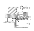
- 1 denotes a container wall in which a pressure relief opening 2 is provided.
- a frame 3 is welded in a gas-tight manner in the pressure relief opening 2 and has an edge 3a which is bent outwards.
- a closure element 4 consisting of a metal foil is gas-welded, which closes the pressure relief opening 2.
- closure element 5 designates a cutting device consisting of a single knife, with which the closure element 4 can be cut open when a predetermined pressure limit is reached, in order to achieve pressure equalization on both sides of the closure element 4.
- the cutting device 5 is held in the starting position by a holding member 6 clamped in place.
- a holding member 6 clamped in place.
- several holding members 6 can also be used (not shown).
- the holding member 6 is positively connected via an intermediate member 7 to the cutting device 5, which in turn is connected to the closure element 4 via a plate 8.
- the closure element 4 is clamped between the plate 8 and a further plate 9.
- the plates 8 and 9 only extend so far that there is still space for the attack of the cutting device 5 between the frame 3 and them.
- the holding member 6 is further provided with a predetermined breaking point 6a in the example shown, which breaks through when the predetermined limit of the pressure acting on the overall arrangement is reached.
- the holding member 6 suddenly breaks through at the predetermined breaking point 6a.
- the pressure acting in the direction of the arrow then pushes the cutting device 5 against the closure element 4, which is cut under the attack of the cutting device.
- the pressure medium then flows out of the pressure relief opening 2 until a pressure equalization occurs in front of and behind the closure element 4.
Landscapes
- General Engineering & Computer Science (AREA)
- Engineering & Computer Science (AREA)
- Mechanical Engineering (AREA)
- Safety Valves (AREA)
- Pressure Vessels And Lids Thereof (AREA)
- Supply Devices, Intensifiers, Converters, And Telemotors (AREA)
- Packages (AREA)
- Food Preservation Except Freezing, Refrigeration, And Drying (AREA)
- Respiratory Apparatuses And Protective Means (AREA)
- External Artificial Organs (AREA)
- Filling Or Discharging Of Gas Storage Vessels (AREA)
- Orthopedics, Nursing, And Contraception (AREA)
- Valves And Accessory Devices For Braking Systems (AREA)
- Control Of Combustion (AREA)
- Cartons (AREA)
Abstract
Description
- Die Erfindung bezieht sich auf eine Sicherheitseinrichtung gegen unzulässigen Druck in einem Behälter nach dem Oberbegriff des Anspruches 1.
- Sicherheitseinrichtungen gegen unzulässigen Druck in einem Behälter sind bereits mannigfach bekannt. Außer Ventilen gibt es unter anderem Einrichtungen, die bei unzulässigem Druck aufreißende Dünnstellen aufweisen, mit ebenen oder konkav-konvexen Berstscheiben ausgerüstet sind, Scherpfropfen besitzen oder durch Sprengkraft zerstörbare Verschlußelemente enthalten.
- Je nach Erfordernissen,werden vielfach auch Sicherheitseinrichtungen verwendet, die jeweils mit einem konkav-konvexen, membranartigen Verschlußelement versehen sind, das sich bei unzulässigem Druck an eine Schneideinrichtung anlegt und von dieser aufgeschnitten wird. Diese Einrichtungen arbeiten jedoch nur bei einer verhältnismäßig großen Anstiegsgeschwindigkeit des auf das Verschlußelement wirkenden Druckes einwandfrei. Bei schleichend ansteigendem Druck wird die zum Durchschneiden des Verschlußelementes erforderliche Mindestschneidarbeit regelmäßig nicht erreicht. Die bekannten Sicherheitseinrichtungen, bei denen die Verschlußelemente durch den anstehenden Druck im Behälter, unter Änderung ihrer Form, gegen eine Schneideinrichtung gedrückt werden, müssen äußerst präzise gefertigt sein und erfordern neben der genügend hohen Geschwindigkeit des Druckanstieges eine besondere Geometrie sowie besondere Materialeigenschaften des Verschlußelementes, wenn sie zufriedenstellend arbeiten sollen (DE-A 28 28 341, 27 o6 723, 25 4o 597).
- Es ist auch eine Sicherheitseinrichtung gegen unzulässigen Druck in einem Behälter nach dem Oberbegriff des Anspruches 1 bekannt. Bei einem Ausführungsbeispiel dieser, in der Art eines Ventils aufgebauten Sicherheitseinrichtung, steht der Innendruck des Behälters an einer Seite des Verschlußelementes an. Auf der Gegenseite des Verschlußelementes liegt ein Ventilteller an, der unter dem Druck einer Feder steht und Schneidpunkte zum Aufschneiden des Verschlußelementes aufweist. Gemäß einem zweiten Ausführungsbeispiel, kann bei der bekannten Sicherheitseinrichtung die Feder entfallen und der Ventilteller in der Art eines Stempels ausgebildet sein, dessen freies Schaftende an einer beidendig eingespannten Querstange angreift, die auf ihrer Rückseite eine Solldruckstelle aufweist. Unter der Voraussetzung, daß der Stempel nach dem zweiten Ausführungsbeispiel mit Schneidpunkten nach dem ersten Ausführungsbeispiel versehen ist, arbeitet die bekannte Sicherheitseinrichtung so, daß sich das Verschlußelement bei unzulässigem Druck im Behälter an die Schneidpunkte anlegt und durch diese aufgeschnitten wird und die Querstange an der dafür vorgesehenen Stelle bricht, so daß der Stempel den ganzen Ventilquerschnitt für eine Druckentlastung frei gibt. Auch hier ist jedoch eine verhältnismäßig große Geschwindigkeit des Druckanstieges im Behälter erforderlich, wenn die Schneidpunkte zur Wirkung kommen sollen. Bei schleichend ansteigendem Druck legt sich das Verschlußelement an die Schneidpunkte an, ohne aufgeschnitten zu werden. Die Anordnung ist so getroffen, daß nur ein rundes, ausbiegbares Verschlußelement verwendbar ist (US-PS 2o 79 164).
- Bei einer weiteren Sicherheitseinrichtung gegen unzulässigen Druck in einem Behälter, ist ebenfalls ein Verschlußelement der im Oberbegriff des Anspruches 1 genannten Art vorgesehen. Wenn Überdruck auftritt, ist dieses Verschlußelement durch eine rohrförmige Schneideinrichtung aufschneidbar, die durch einen Kipphebel in der Ausgangslage gehalten ist und unter dem Druck einer Feder steht. Der Kipphebel ist durch eine aufwendige Manostateinrichtung zur Freigabe der Schneideinrichtung ausseiner Ausgangslage ausschwenkbar. Die Anordnung ist träge (FR-PS 2o 44 512).
- Ferner ist eine Sicherheitseinrichtung gegen unzulässigen Druck in einem Behälter bekannt, bei der ein Verschlußelement der im Oberbegriff des Anspruches 1 genannten Art mit einem Kippmesser aufschneidbar ist. Das Kippmesser ist bei auftretendem Überdruck in die Kipplage durch eine Betätigungsstange auslenkbar, die an einer in ihrem Rücken angeordnete unter dem Druck im Behälter stehende Membrane angreift. Diese bekannte Sicherheitseinrichtung ist sehr aufwendig. Die Schneideinrichtung wird nur kraftschlüssig in der Ausgangslage gehalten (US-PS 32 79 647).
- Eine ebenfalls bekannte Sicherheitseinrichtung gegen unzulässigen Druck in einem Behälter arbeitet so, daß eine ringförmige, Zweilagen-Schnappfeder ein hohlzylindrisches Messer gegen einen an einer als Verschlußelement ausgebildeten Membrane anstehenden Druck eines Mediums in ihrer einen Schnapplage hält. Wenn der Druck die Kraft der Schnappfeder überschreitet, baucht sich die Membrane aus und bewegt über Zwischenglieder die Schnappfeder in ihre andere Schnapplage. Die Schnappfeder stößt, dabei das Messer gegen die Membrane, wodurch diese zerstört wird und die erstrebte Druckentlastung erfolgt (US-PS 34 82 732).
- Dem bisher beschriebenen Stand der Technik ähnliche Sicherheitseinrichtungen sind aus den Druckschriften FR-PS 22 52 519, FR-PS 15 95 660, FR-PS 23 55 226, US-PS 19 70 718, DE-PS 568 051, DE-OS 27 27 935, US-PS 31 45 573, DE-OS 17 90 137 bekannt. Die in diesen Druckschriften beschriebenen Gegenstände liegen dem im Oberbegriff des Anspruches 1 genannten Gegenstand ferner als die vorstehend beschriebenen Sicherheitseinrichtungen.
- Aufgabe der Erfindung ist es, die im Oberbegriff des Anspruches 1 angegebene Sicherheitseinrichtung gegen unzulässigen Druck in einem Behälter so auszubilden, daß sie auch bei schleichendem Anstieg des auf das Verschlußelement wirkenden Druckes ihre Sicherheitsaufgabe einwandfrei erfüllt, daß sie einfach aufgebaut ist, daß die Geometrie ihres Verschlußelementes weitgehend frei wählbar ist und daß das Verschlußelement,außer der Verschlußaufgabe, ständig inaktiv bleibt, so daß an seine Materialeigenschaften, abgesehen von der mechanischen Festigkeit und der Korrosionsfestigkeit, keine besonderen Anforderungen gestellt werden müssen.
- Die gestellte Aufgabe wird erfindungsgemäß durch die im kennzeichnenden Teil des Anspruches 1 angegebene Ausbildung gelöst.
- Die gefundene Lösung zeichnet sich dadurch aus, daß beim Erreichen der Druckgrenze die Schneideinrichtung nicht schleichend sondern plötzlich, mit dem gewünschten Ergebnis aktiv wird.
- Ein Ausführungsbeispiel des Erfindungsgegenstandes ist in der Zeichnung rein schematisch dargestellt, die im Schnitt einen Aufriß einer Sicherheitseinrichtung zeigt, bei der alle wesentlichen Elemente formschlüssig miteinander verbunden sind.
- In der Zeichnung ist mit 1 eine Behälterwand bezeichnet, in der eine Druckentlastungsöffnung 2 vorgesehen ist.
- In der Druckentlastungsöffnung 2 ist gasdicht ein Rahmen 3 eingeschweißt, der einen nach außen umgebogenen Rand 3a aufweist. Auf dem Rand 3a ist ein aus einer Metallfolie bestehendes Verschlußelement 4 gasicht angeschweißt, das die Druckentlastungsöffnung 2 verschließt.
- Mit 5 ist eine aus einem einzigen Messer bestehende Schneideinrichtung bezeichnet, mit der bei Erreichen einer vorgegebenen Druckgrenze das Verschlußelement 4 aufschneidbar ist, um einen Druckausgleich beidseits des Verschlußelementes 4 zu erreichen.
- Die Schneideinrichtung 5 ist durch ein ortsfest eingespanntes Halteglied 6 in der Ausgangslage gehalten. Anstelle nur eines Haltegliedes 6 können auch mehrere Halteglieder 6 verwendet werden (nicht dargestellt).
- Das Halteglied 6 ist über ein Zwischenglied 7 mit der Schneideinrichtung 5 formschlüssig verbunden, welche ihrerseits mit dem Verschlußelement 4 über eine Platte 8 verbunden ist. Das Verschlußelement 4 ist zwischen der Platte 8 sowie einer weiteren Platte 9 eingespannt.
- Die Platten8 und 9 erstrecken sich nur soweit, daß zwischen dem Rahmen 3 und ihnen noch Platz für den Angriff der Schneideinrichtung 5 ist.
- Das Halteglied 6 ist ferner mit einer im dargestellten Beispiel aus einer Ringnut bestehenden Sollbruchstelle 6a versehen, die beim Erreichen der vorgegebenen Grenze des auf die Gesamtanordnung wirkenden Druckes durchbricht.
- Wirkungsweise:
- Unterhalb der vorgegebenen Druckgrenze bleibt die gesamte Anordnung in Ruhe.
- Sobald die vorgegebene Druckgrenze erreicht ist, bricht das Halteglied 6 an der Sollbruchstelle 6a plötzlich durch. Der in Pfeilrichtung wirkende Druck stöst daraufhin die Schneideinrichtung 5 gegen das Verschlußelement 4, welches unter dem Angriff der Schneideinrichtung durchgeschnitten wird. Anschliessend strömt das Druckmedium solange aus der Druckentlastungsöffnung 2 aus, bis sich vor- und-hinter dem Verschlußelement 4 ein Druckausgleich einstellt.
Claims (2)
Priority Applications (1)
| Application Number | Priority Date | Filing Date | Title |
|---|---|---|---|
| AT84102607T ATE21540T1 (de) | 1983-03-24 | 1984-03-09 | Sicherheitseinrichtung gegen unzulaessigen druck in einem behaelter. |
Applications Claiming Priority (2)
| Application Number | Priority Date | Filing Date | Title |
|---|---|---|---|
| DE3310782 | 1983-03-24 | ||
| DE3310782A DE3310782C1 (de) | 1983-03-24 | 1983-03-24 | Sicherheitseinrichtung gegen unzulaessigen Druck in einem Behaelter |
Publications (2)
| Publication Number | Publication Date |
|---|---|
| EP0120380A1 true EP0120380A1 (de) | 1984-10-03 |
| EP0120380B1 EP0120380B1 (de) | 1986-08-20 |
Family
ID=6194565
Family Applications (1)
| Application Number | Title | Priority Date | Filing Date |
|---|---|---|---|
| EP84102607A Expired EP0120380B1 (de) | 1983-03-24 | 1984-03-09 | Sicherheitseinrichtung gegen unzulässigen Druck in einem Behälter |
Country Status (10)
| Country | Link |
|---|---|
| US (1) | US4476991A (de) |
| EP (1) | EP0120380B1 (de) |
| KR (1) | KR910006559B1 (de) |
| AT (1) | ATE21540T1 (de) |
| BR (1) | BR8401322A (de) |
| DE (2) | DE3310782C1 (de) |
| EG (1) | EG15659A (de) |
| IN (1) | IN159171B (de) |
| YU (1) | YU21684A (de) |
| ZA (1) | ZA842160B (de) |
Cited By (2)
| Publication number | Priority date | Publication date | Assignee | Title |
|---|---|---|---|---|
| DE4041979A1 (de) * | 1990-12-21 | 1992-07-02 | Siemens Ag | Vorrichtung zur druckentlastung an einer metallgekapselten, druckgasisolierten schaltanlage |
| DE102013107559A1 (de) * | 2013-07-16 | 2015-01-22 | Maschinenfabrik Reinhausen Gmbh | Bersteinrichtung für ein Hochspannungsgerät |
Families Citing this family (1)
| Publication number | Priority date | Publication date | Assignee | Title |
|---|---|---|---|---|
| US5284177A (en) * | 1990-11-13 | 1994-02-08 | Sandia Corporation | Non-reclosing pressure relief device for vacuum systems |
Citations (8)
| Publication number | Priority date | Publication date | Assignee | Title |
|---|---|---|---|---|
| DE568051C (de) * | 1932-01-20 | 1933-01-13 | Neumann Berthold | Anordnung zur schnellen Beseitigung von UEberdrucken |
| US1970718A (en) * | 1932-01-09 | 1934-08-21 | Standard Oil Dev Co | Frangible rod and disk type safety valve |
| US2079164A (en) * | 1935-12-06 | 1937-05-04 | Morrison Brothers Company | Relief valve |
| US3279647A (en) * | 1963-11-20 | 1966-10-18 | Shell Oil Co | Membrane-type safety device |
| FR1595660A (de) * | 1968-02-08 | 1970-06-15 | ||
| FR2044512A5 (en) * | 1969-05-23 | 1971-02-19 | Bvs | Safety device for pressure vessel |
| FR2252519A1 (en) * | 1973-11-26 | 1975-06-20 | Labem | Safety valve for pressurised storage container - overpressure releases plunger to rupture sealing diaphragm |
| FR2355226A1 (fr) * | 1976-06-18 | 1978-01-13 | Euratom | Valve de securite a membrane |
Family Cites Families (14)
| Publication number | Priority date | Publication date | Assignee | Title |
|---|---|---|---|---|
| US2954897A (en) * | 1956-02-15 | 1960-10-04 | Black Sivalls & Bryson Inc | Safety pressure relief device |
| US3145573A (en) * | 1962-12-21 | 1964-08-25 | Specialties Dev Corp | Control head |
| US3482732A (en) * | 1967-10-19 | 1969-12-09 | Allen V C Davis | Frangible safety means for relieving excess fluid pressure |
| DE6751599U (de) * | 1968-09-17 | 1969-01-30 | Siemens Ag | Unter druck stehendes gehaeuse mit einer entlastungsoeffnung |
| FR2269013B1 (de) * | 1974-04-26 | 1977-10-21 | Alsthom Cgee | |
| US3908684A (en) * | 1974-11-04 | 1975-09-30 | Black Sivalls & Bryson Inc | Rupture disk assembly |
| US4119112A (en) * | 1976-07-19 | 1978-10-10 | Pullman Incorporated | Pressure relief valve |
| US4079854A (en) * | 1976-08-09 | 1978-03-21 | Continental Disc Corporation | Rupture disc pressure relief device |
| US4158422A (en) * | 1977-09-12 | 1979-06-19 | Black, Sivalls & Bryson, Inc. | Safety pressure relief apparatus |
| US4301938A (en) * | 1978-08-25 | 1981-11-24 | Bs&B Safety Systems, Inc. | Safety pressure relief device |
| US4345611A (en) * | 1979-06-07 | 1982-08-24 | Sanyo Electric Co., Ltd. | Safety valve means for battery |
| US4363418A (en) * | 1982-02-11 | 1982-12-14 | Bs&B Safety Systems, Inc. | Knife blade apparatus for severing rupture disks |
| US4394926A (en) * | 1982-02-18 | 1983-07-26 | Bs & B Safety Systems, Inc. | Reverse buckling rupture disk apparatus |
| US4434905A (en) * | 1982-03-31 | 1984-03-06 | Bs&B Safety Systems, Inc. | Rupturable low pressure relief apparatus |
-
1983
- 1983-03-24 DE DE3310782A patent/DE3310782C1/de not_active Expired
- 1983-12-22 IN IN1573/CAL/83A patent/IN159171B/en unknown
-
1984
- 1984-01-30 KR KR1019840000413A patent/KR910006559B1/ko not_active Expired
- 1984-02-07 YU YU00216/84A patent/YU21684A/xx unknown
- 1984-03-09 US US06/588,019 patent/US4476991A/en not_active Expired - Fee Related
- 1984-03-09 AT AT84102607T patent/ATE21540T1/de not_active IP Right Cessation
- 1984-03-09 EP EP84102607A patent/EP0120380B1/de not_active Expired
- 1984-03-09 DE DE8484102607T patent/DE3460497D1/de not_active Expired
- 1984-03-21 EG EG182/84D patent/EG15659A/xx active
- 1984-03-22 BR BR8401322A patent/BR8401322A/pt not_active IP Right Cessation
- 1984-03-23 ZA ZA842160A patent/ZA842160B/xx unknown
Patent Citations (8)
| Publication number | Priority date | Publication date | Assignee | Title |
|---|---|---|---|---|
| US1970718A (en) * | 1932-01-09 | 1934-08-21 | Standard Oil Dev Co | Frangible rod and disk type safety valve |
| DE568051C (de) * | 1932-01-20 | 1933-01-13 | Neumann Berthold | Anordnung zur schnellen Beseitigung von UEberdrucken |
| US2079164A (en) * | 1935-12-06 | 1937-05-04 | Morrison Brothers Company | Relief valve |
| US3279647A (en) * | 1963-11-20 | 1966-10-18 | Shell Oil Co | Membrane-type safety device |
| FR1595660A (de) * | 1968-02-08 | 1970-06-15 | ||
| FR2044512A5 (en) * | 1969-05-23 | 1971-02-19 | Bvs | Safety device for pressure vessel |
| FR2252519A1 (en) * | 1973-11-26 | 1975-06-20 | Labem | Safety valve for pressurised storage container - overpressure releases plunger to rupture sealing diaphragm |
| FR2355226A1 (fr) * | 1976-06-18 | 1978-01-13 | Euratom | Valve de securite a membrane |
Cited By (3)
| Publication number | Priority date | Publication date | Assignee | Title |
|---|---|---|---|---|
| DE4041979A1 (de) * | 1990-12-21 | 1992-07-02 | Siemens Ag | Vorrichtung zur druckentlastung an einer metallgekapselten, druckgasisolierten schaltanlage |
| DE102013107559A1 (de) * | 2013-07-16 | 2015-01-22 | Maschinenfabrik Reinhausen Gmbh | Bersteinrichtung für ein Hochspannungsgerät |
| EP3022745B1 (de) * | 2013-07-16 | 2020-02-19 | Maschinenfabrik Reinhausen GmbH | Bersteinrichtung für ein hochspannungsgerät |
Also Published As
| Publication number | Publication date |
|---|---|
| EG15659A (en) | 1987-05-30 |
| IN159171B (de) | 1987-04-04 |
| DE3310782C1 (de) | 1984-07-19 |
| ATE21540T1 (de) | 1986-09-15 |
| EP0120380B1 (de) | 1986-08-20 |
| YU21684A (en) | 1988-04-30 |
| KR840008039A (ko) | 1984-12-12 |
| US4476991A (en) | 1984-10-16 |
| ZA842160B (en) | 1984-10-31 |
| BR8401322A (pt) | 1984-10-30 |
| KR910006559B1 (ko) | 1991-08-28 |
| DE3460497D1 (en) | 1986-09-25 |
Similar Documents
| Publication | Publication Date | Title |
|---|---|---|
| DE2828341C2 (de) | Überdruck-Sicherung mit einer Umkehr-Bruchscheibe | |
| EP3329528B1 (de) | Druckausgleichsvorrichtung | |
| DE2121389C3 (de) | Schnell zu öffnendes Absperrventil für unter Druck stehende Strömungsmittel | |
| DE2706723C2 (de) | Drucksicherheitseinrichtung für Druckgefäße o. dgl. | |
| EP0350565B1 (de) | Schmelz-Sicherheitseinrichtung für das Gassystem hydropneumatischer Druckspeicher | |
| EP3354948B1 (de) | Berstscheibenanordnung mit einer berstscheibe und einem aktuator zum herabsetzen des berstdrucks | |
| DE60033706T2 (de) | Sicherheitventil mit Sollbruchstelle | |
| DE2335342A1 (de) | Sicherheitsvorrichtung zum begrenzen des druckes eines fluids | |
| DE3876696T2 (de) | Umkehrberstscheibe zur druckentlastung. | |
| EP0288827A2 (de) | Vorrichtung zur Messung von Drücken | |
| DE102004037060A1 (de) | Stellantrieb für eine Vorrichtung zum Anheben einer Motorhaube und Verfahren zum Betreiben eines solchen Stellantriebs | |
| WO2022226557A1 (de) | Pyrotechnischer stromtrenner | |
| DE3702557C2 (de) | Druckentlastungsvorrichtung | |
| EP0120380B1 (de) | Sicherheitseinrichtung gegen unzulässigen Druck in einem Behälter | |
| DE69810525T2 (de) | Schnellöffnungsmechanismus mit Dämpfung | |
| DE102017001155A1 (de) | Vorrichtung zum Öffnen von Getränkepulverkapseln | |
| DE69409470T2 (de) | Sicherheitsvorrichtung zur Öffnung oder Schliessung eines Schiebers | |
| DE1079236B (de) | Vorrichtung zur Abbremsung des Falles eines Kernreaktor-Steuer- oder Abschaltstabes | |
| DE2412080C3 (de) | Ventil | |
| DE102014017232A1 (de) | Batteriegehäuseanordnung mit einem plattenförmigen Element für ein Kraftfahrzeug und Verfahren zur Druckentlastung einer derartigen Batteriegehäuseanordnung | |
| EP0684189B1 (de) | Originalitäts-Sicherungsvorrichtung für Behälterverschlüsse | |
| DE2821588A1 (de) | Ueberdruckventil | |
| DE1955703C3 (de) | Elektrisch zu zündendes Schaltelement | |
| DE1140770B (de) | UEberlastsicherung mit Scherstift fuer land-wirtschaftliche Maschinen und Geraete, insbesondere Pfluege | |
| DE2518035A1 (de) | Sicherheitsventil fuer druckgasbehaelter |
Legal Events
| Date | Code | Title | Description |
|---|---|---|---|
| PUAI | Public reference made under article 153(3) epc to a published international application that has entered the european phase |
Free format text: ORIGINAL CODE: 0009012 |
|
| AK | Designated contracting states |
Designated state(s): AT CH DE FR GB IT LI SE |
|
| 17P | Request for examination filed |
Effective date: 19841026 |
|
| GRAA | (expected) grant |
Free format text: ORIGINAL CODE: 0009210 |
|
| AK | Designated contracting states |
Kind code of ref document: B1 Designated state(s): AT CH DE FR GB IT LI SE |
|
| REF | Corresponds to: |
Ref document number: 21540 Country of ref document: AT Date of ref document: 19860915 Kind code of ref document: T |
|
| REF | Corresponds to: |
Ref document number: 3460497 Country of ref document: DE Date of ref document: 19860925 |
|
| ET | Fr: translation filed | ||
| ITF | It: translation for a ep patent filed | ||
| PLBE | No opposition filed within time limit |
Free format text: ORIGINAL CODE: 0009261 |
|
| STAA | Information on the status of an ep patent application or granted ep patent |
Free format text: STATUS: NO OPPOSITION FILED WITHIN TIME LIMIT |
|
| 26N | No opposition filed | ||
| PGFP | Annual fee paid to national office [announced via postgrant information from national office to epo] |
Ref country code: AT Payment date: 19910301 Year of fee payment: 8 |
|
| ITTA | It: last paid annual fee | ||
| PG25 | Lapsed in a contracting state [announced via postgrant information from national office to epo] |
Ref country code: AT Effective date: 19920309 |
|
| EAL | Se: european patent in force in sweden |
Ref document number: 84102607.3 |
|
| PGFP | Annual fee paid to national office [announced via postgrant information from national office to epo] |
Ref country code: DE Payment date: 19970521 Year of fee payment: 14 |
|
| PGFP | Annual fee paid to national office [announced via postgrant information from national office to epo] |
Ref country code: CH Payment date: 19970620 Year of fee payment: 14 |
|
| PGFP | Annual fee paid to national office [announced via postgrant information from national office to epo] |
Ref country code: GB Payment date: 19980211 Year of fee payment: 15 |
|
| PGFP | Annual fee paid to national office [announced via postgrant information from national office to epo] |
Ref country code: SE Payment date: 19980325 Year of fee payment: 15 |
|
| PGFP | Annual fee paid to national office [announced via postgrant information from national office to epo] |
Ref country code: FR Payment date: 19980327 Year of fee payment: 15 |
|
| PG25 | Lapsed in a contracting state [announced via postgrant information from national office to epo] |
Ref country code: LI Free format text: LAPSE BECAUSE OF NON-PAYMENT OF DUE FEES Effective date: 19980331 Ref country code: CH Free format text: LAPSE BECAUSE OF NON-PAYMENT OF DUE FEES Effective date: 19980331 |
|
| REG | Reference to a national code |
Ref country code: CH Ref legal event code: PL |
|
| PG25 | Lapsed in a contracting state [announced via postgrant information from national office to epo] |
Ref country code: DE Free format text: LAPSE BECAUSE OF NON-PAYMENT OF DUE FEES Effective date: 19981201 |
|
| PG25 | Lapsed in a contracting state [announced via postgrant information from national office to epo] |
Ref country code: GB Free format text: LAPSE BECAUSE OF NON-PAYMENT OF DUE FEES Effective date: 19990309 |
|
| PG25 | Lapsed in a contracting state [announced via postgrant information from national office to epo] |
Ref country code: SE Free format text: LAPSE BECAUSE OF NON-PAYMENT OF DUE FEES Effective date: 19990310 |
|
| GBPC | Gb: european patent ceased through non-payment of renewal fee |
Effective date: 19990309 |
|
| EUG | Se: european patent has lapsed |
Ref document number: 84102607.3 |
|
| PG25 | Lapsed in a contracting state [announced via postgrant information from national office to epo] |
Ref country code: FR Free format text: LAPSE BECAUSE OF NON-PAYMENT OF DUE FEES Effective date: 19991130 |
|
| EUG | Se: european patent has lapsed |
Ref document number: 84102607.3 |
|
| REG | Reference to a national code |
Ref country code: FR Ref legal event code: ST |