EP0120407A1 - Dispositif de guidage en translation ou en rotation - Google Patents
Dispositif de guidage en translation ou en rotation Download PDFInfo
- Publication number
- EP0120407A1 EP0120407A1 EP84102781A EP84102781A EP0120407A1 EP 0120407 A1 EP0120407 A1 EP 0120407A1 EP 84102781 A EP84102781 A EP 84102781A EP 84102781 A EP84102781 A EP 84102781A EP 0120407 A1 EP0120407 A1 EP 0120407A1
- Authority
- EP
- European Patent Office
- Prior art keywords
- guide
- balls
- linear
- ball
- group
- Prior art date
- Legal status (The legal status is an assumption and is not a legal conclusion. Google has not performed a legal analysis and makes no representation as to the accuracy of the status listed.)
- Granted
Links
- 230000006835 compression Effects 0.000 claims description 3
- 238000007906 compression Methods 0.000 claims description 3
- 238000005096 rolling process Methods 0.000 claims description 2
- 238000006073 displacement reaction Methods 0.000 claims 1
- 238000003754 machining Methods 0.000 description 2
- 241001295925 Gegenes Species 0.000 description 1
- 238000011089 mechanical engineering Methods 0.000 description 1
- 230000036316 preload Effects 0.000 description 1
- 230000002787 reinforcement Effects 0.000 description 1
Images

Classifications
-
- F—MECHANICAL ENGINEERING; LIGHTING; HEATING; WEAPONS; BLASTING
- F16—ENGINEERING ELEMENTS AND UNITS; GENERAL MEASURES FOR PRODUCING AND MAINTAINING EFFECTIVE FUNCTIONING OF MACHINES OR INSTALLATIONS; THERMAL INSULATION IN GENERAL
- F16C—SHAFTS; FLEXIBLE SHAFTS; ELEMENTS OR CRANKSHAFT MECHANISMS; ROTARY BODIES OTHER THAN GEARING ELEMENTS; BEARINGS
- F16C29/00—Bearings for parts moving only linearly
- F16C29/04—Ball or roller bearings
- F16C29/045—Ball or roller bearings having rolling elements journaled in one of the moving parts
- F16C29/046—Ball or roller bearings having rolling elements journaled in one of the moving parts with balls journaled in pockets
-
- F—MECHANICAL ENGINEERING; LIGHTING; HEATING; WEAPONS; BLASTING
- F16—ENGINEERING ELEMENTS AND UNITS; GENERAL MEASURES FOR PRODUCING AND MAINTAINING EFFECTIVE FUNCTIONING OF MACHINES OR INSTALLATIONS; THERMAL INSULATION IN GENERAL
- F16C—SHAFTS; FLEXIBLE SHAFTS; ELEMENTS OR CRANKSHAFT MECHANISMS; ROTARY BODIES OTHER THAN GEARING ELEMENTS; BEARINGS
- F16C19/00—Bearings with rolling contact, for exclusively rotary movement
- F16C19/50—Other types of ball or roller bearings
-
- F—MECHANICAL ENGINEERING; LIGHTING; HEATING; WEAPONS; BLASTING
- F16—ENGINEERING ELEMENTS AND UNITS; GENERAL MEASURES FOR PRODUCING AND MAINTAINING EFFECTIVE FUNCTIONING OF MACHINES OR INSTALLATIONS; THERMAL INSULATION IN GENERAL
- F16C—SHAFTS; FLEXIBLE SHAFTS; ELEMENTS OR CRANKSHAFT MECHANISMS; ROTARY BODIES OTHER THAN GEARING ELEMENTS; BEARINGS
- F16C29/00—Bearings for parts moving only linearly
- F16C29/04—Ball or roller bearings
Definitions
- the invention relates to a linear or rotary guide with a guide body and a cage which can be moved relative thereto, the guide body having guide surfaces on which guide balls mounted in the cage can be rolled, and at least one group of the guide balls effecting positive locking.
- This configuration allows the game to be absorbed by the elastic force and to obtain a defined friction along the guide.
- each of the guide balls is mounted in the cage by means of a roller bearing, the axis of which runs perpendicular to the guide direction
- the roller bearing of the ball held under elastic prestress is axially displaceably mounted in the cage and by means of a compression spring in the direction of the corresponding one Guide surface resilient.
- the prestressing forces can thus be adjusted in a simple manner by the choice of the corresponding compression springs.
- tion balls arranged elastically in this way.
- the number and arrangement of the same can be determined in individual cases by the fact that at least one guide ball, which is held under elastic tension, is required for each group of guide balls, which together bring about positive positive guidance.
- the linear guide shown in FIGS. 1 and 2 has a cage designed as a slide 1, in which the guide balls 2 ', 2 are mounted.
- the guide body is designed as a flat bar 3 with V-shaped narrow sides 4 converging towards the outside, which form four guide surfaces, along which the guide balls 2 roll. These are each supported on the balls of a ball bearing 5, which also absorbs axial forces as an angular bearing.
- the four guide rollers 2 shown in FIG. 2 together form a group lying in one plane, which surround the bar 3 in a form-fitting manner. Overall, the linear guide shown has two such groups, as can be seen from FIG. 1.
- a corresponding guide ball 2 ' is elastically supported, so that it is pre-stressed against the corresponding guide surface 3, while the rest Balls are rigidly supported.
- the elastic mounting is accomplished in that the corresponding ball bearing 5 1 is held axially displaceably in the carriage 1, the ball bearing being pressed against the guide surface 4 by a spring 6.
- the spring 6 is a plate spring is preferably used, since only a very minor H ub is necessary, which rests with its large radius on the outer ring of the ball bearing 5 '.
- the spring force can be adjusted by means of an adjusting screw 7 '. As can easily be seen for geometric reasons, the rotation of the guide balls 2, 2 'takes place exclusively in the axis of the ball bearings.
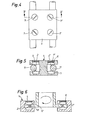
- the movement of the guide balls 2, 2 'already explained during operation allows the guide balls to be moved each time to be supported on the inner ring 10 of a rolling bearing, as is evident from the variant according to FIG. 3.
- the inner ring is lightly sanded to ensure a good fit. This design has the advantage that no additional measures have to be taken to prevent the bearing balls from tipping out.
- the linear guide shown on the basis of the examples explained can be used for each group with strips 3, which are not excessively precisely machined with regard to the parallelism of the guide surfaces, thanks to the guide ball 2 'held under elastic prestress. Inaccuracies in this regard are absorbed by said guide ball 2 '.
- the direction of loading of the arrangement is preferably selected in use so that this guide ball does not have to absorb a major part of the force.
- the bias can be adjusted to the prevailing force relationships and with the other adjusting screws 7, which can be fixed with a locking screw 15, the mutual position of the bar 3 and guide balls can be adjusted.
- the strip 3 can be provided with a counter plate 9 for reinforcement and stiffening, so that it has a T-shape.
- a second embodiment of the invention is shown, two rods 11 being used as the guide body, along which the guide balls 2, 2 'roll.
- the arrangement corresponds essentially to that described above, the guide surfaces being formed by the rod flanks.
- the rods 11 are clamped at the ends and run parallel to one another. Small deviations from the ideal position can in turn be absorbed by the guide ball 2 'which is under elastic prestress. Since the distance between the guide balls lying opposite one another in pairs is 2.2 ', and therefore they are not hold each other in place, these are used in the assembly of the carriage 1 on the rods 11. In this arrangement too, as in the above-described embodiments, it is sufficient if only one guide ball 2, 2 'can be adjusted per pair, for which purpose screws 7 are also provided. This simplification is due to the spring-loaded guide balls 2 '.
- FIG. 6 schematically shows a rotation guide in which the guide body has the shape of a disk 12 which has guide surfaces 13 converging outwards in a V-shape on its periphery.
- the cage 14 surrounds the guide body in a ring shape and contains the guide balls 2, 2 ', which are arranged in pairs. At least three pairs of guide balls are provided and together form a group, which brings about positive positive guidance. As a result, at least one of these guide balls 2 'is mounted under elastic prestress, as is shown schematically in FIG. 6. For the rest, reference can be made to the examples explained above.
- linear and rotary guides described allow multiple use, in particular in the field of microtechnology and in medium-sized mechanical engineering, where high accuracy is required when the load is not too high, such as in industrial robots.
- the machining accuracy of the guide surfaces can essentially be limited to the accuracy required during use and does not have to go beyond this for the satisfactory guide properties. In particular, extensive freedom of play can be achieved.
Landscapes
- Engineering & Computer Science (AREA)
- General Engineering & Computer Science (AREA)
- Mechanical Engineering (AREA)
- Bearings For Parts Moving Linearly (AREA)
Applications Claiming Priority (2)
| Application Number | Priority Date | Filing Date | Title |
|---|---|---|---|
| CH1745/83A CH659690A5 (de) | 1983-03-29 | 1983-03-29 | Linear- oder rotationsfuehrung. |
| CH1745/83 | 1983-03-29 |
Publications (2)
| Publication Number | Publication Date |
|---|---|
| EP0120407A1 true EP0120407A1 (fr) | 1984-10-03 |
| EP0120407B1 EP0120407B1 (fr) | 1987-11-04 |
Family
ID=4217588
Family Applications (1)
| Application Number | Title | Priority Date | Filing Date |
|---|---|---|---|
| EP84102781A Expired EP0120407B1 (fr) | 1983-03-29 | 1984-03-14 | Dispositif de guidage en translation ou en rotation |
Country Status (4)
| Country | Link |
|---|---|
| US (1) | US4579396A (fr) |
| EP (1) | EP0120407B1 (fr) |
| CH (1) | CH659690A5 (fr) |
| DE (1) | DE3467216D1 (fr) |
Cited By (1)
| Publication number | Priority date | Publication date | Assignee | Title |
|---|---|---|---|---|
| DE4324059A1 (de) * | 1993-07-17 | 1995-01-19 | Manfred Artkaemper | Führungselement für Schlittenführungen sowie Schlittenführung |
Families Citing this family (5)
| Publication number | Priority date | Publication date | Assignee | Title |
|---|---|---|---|---|
| SE9603163L (sv) * | 1996-08-30 | 1997-12-08 | Kolungen Ab | Styrningssystem mellan en slid och en gejder |
| DE10220063A1 (de) * | 2002-05-04 | 2003-11-13 | Ina Schaeffler Kg | Führung |
| US8033245B2 (en) * | 2004-02-12 | 2011-10-11 | Applied Materials, Inc. | Substrate support bushing |
| US10567558B2 (en) * | 2017-12-06 | 2020-02-18 | Shenzhen Zhaowei Machinery & Electronics Co., Ltd. | Camera extending and retracting device and mobile phone |
| CN117189777B (zh) * | 2023-11-06 | 2024-02-20 | 江苏恒立精密工业有限公司 | 精密滚柱直线导轨 |
Citations (5)
| Publication number | Priority date | Publication date | Assignee | Title |
|---|---|---|---|---|
| FR739913A (fr) * | 1931-01-13 | 1933-01-19 | ||
| DE649218C (de) * | 1935-06-08 | 1937-08-18 | Zeiss Carl Fa | Lagerung |
| CH326285A (fr) * | 1954-09-30 | 1957-12-15 | Amagasaki Seitetsu Kabushiki K | Palier de butée |
| US3407011A (en) * | 1966-03-15 | 1968-10-22 | Zeidler Herman Rudolf | Adjustable v bearing for guiding translating shafts |
| GB2013832A (en) * | 1978-02-04 | 1979-08-15 | Uni Cardan Ag | Telescopic drive shaft |
Family Cites Families (3)
| Publication number | Priority date | Publication date | Assignee | Title |
|---|---|---|---|---|
| US2299677A (en) * | 1940-06-10 | 1942-10-20 | Monarch Machine Tool Co | Taper attachment construction |
| US3001835A (en) * | 1959-07-20 | 1961-09-26 | Ford Motor Co | Seat adjuster track mechanism |
| NL163711C (nl) * | 1976-09-09 | 1980-10-15 | Regout Nv Thomas | Telescopische railgeleiding. |
-
1983
- 1983-03-29 CH CH1745/83A patent/CH659690A5/de not_active IP Right Cessation
-
1984
- 1984-03-14 DE DE8484102781T patent/DE3467216D1/de not_active Expired
- 1984-03-14 EP EP84102781A patent/EP0120407B1/fr not_active Expired
- 1984-03-19 US US06/590,703 patent/US4579396A/en not_active Expired - Fee Related
Patent Citations (5)
| Publication number | Priority date | Publication date | Assignee | Title |
|---|---|---|---|---|
| FR739913A (fr) * | 1931-01-13 | 1933-01-19 | ||
| DE649218C (de) * | 1935-06-08 | 1937-08-18 | Zeiss Carl Fa | Lagerung |
| CH326285A (fr) * | 1954-09-30 | 1957-12-15 | Amagasaki Seitetsu Kabushiki K | Palier de butée |
| US3407011A (en) * | 1966-03-15 | 1968-10-22 | Zeidler Herman Rudolf | Adjustable v bearing for guiding translating shafts |
| GB2013832A (en) * | 1978-02-04 | 1979-08-15 | Uni Cardan Ag | Telescopic drive shaft |
Cited By (1)
| Publication number | Priority date | Publication date | Assignee | Title |
|---|---|---|---|---|
| DE4324059A1 (de) * | 1993-07-17 | 1995-01-19 | Manfred Artkaemper | Führungselement für Schlittenführungen sowie Schlittenführung |
Also Published As
| Publication number | Publication date |
|---|---|
| CH659690A5 (de) | 1987-02-13 |
| DE3467216D1 (en) | 1987-12-10 |
| EP0120407B1 (fr) | 1987-11-04 |
| US4579396A (en) | 1986-04-01 |
Similar Documents
| Publication | Publication Date | Title |
|---|---|---|
| DE19711422C2 (de) | Rollenmutteranordnung und Linearversatzvorrichtung mit einer solchen Rollenmutteranordnung | |
| DE3909292C2 (de) | Längs- und Quer-Tischführungs- und -drehmechanismus | |
| DE3307010C2 (fr) | ||
| DE3619728C2 (fr) | ||
| DE2941475A1 (de) | Linearlagervorrichtung | |
| CH660623A5 (de) | In achsrichtung hinsichtlich vorspannung einstellbare waelzlageranordnung mit zwei lagerstellen fuer eine zu lagernde welle. | |
| DE3429897A1 (de) | Einstellbare geradfuehrung fuer insbesondere werkzeugmaschinen | |
| DE3417588C2 (de) | Gekrümmte Lagereinheit | |
| DE3140091A1 (de) | Zweireihiges schraegkugellager | |
| DE69119373T2 (de) | Tisch für linearführung | |
| DE69208600T2 (de) | Wälzgelagerte Linearführungseinheit | |
| DE2231541A1 (de) | Rollspindel | |
| EP0120407A1 (fr) | Dispositif de guidage en translation ou en rotation | |
| DE1575542B2 (de) | Praezise nachstellbare laengsfuehrung | |
| EP0171700A2 (fr) | Palier à rouleaux ajustable | |
| EP0003802B1 (fr) | Palier sans jeu pour vis-mère | |
| DE3419450A1 (de) | Lineares gleitrollenlager | |
| DE60133131T2 (de) | Rundstrickmaschine | |
| DE3418621A1 (de) | Waelzlager | |
| DE6937288U (de) | Lineares umlaufrollenlager. | |
| DE1039790B (de) | Ein- oder mehrreihiges Waelzlager | |
| DE102015000253B3 (de) | Pendelhalter mit gedämpfter Kupplung | |
| DE2708662C2 (de) | Selbsthemmend wirksame Führung für ein axial vorgeschobenes, zylindrisches Werkstück | |
| DE3419447A1 (de) | Lineares gleitrollenlager | |
| DE69008383T2 (de) | Verfahren und Vorrichtung zur spielfreien Montage eines sich drehenden Teiles zwischen zwei Lagern. |
Legal Events
| Date | Code | Title | Description |
|---|---|---|---|
| PUAI | Public reference made under article 153(3) epc to a published international application that has entered the european phase |
Free format text: ORIGINAL CODE: 0009012 |
|
| AK | Designated contracting states |
Designated state(s): DE FR GB IT NL |
|
| 17P | Request for examination filed |
Effective date: 19850406 |
|
| R17P | Request for examination filed (corrected) |
Effective date: 19850403 |
|
| 17Q | First examination report despatched |
Effective date: 19860227 |
|
| GRAA | (expected) grant |
Free format text: ORIGINAL CODE: 0009210 |
|
| AK | Designated contracting states |
Kind code of ref document: B1 Designated state(s): DE FR GB IT NL |
|
| PG25 | Lapsed in a contracting state [announced via postgrant information from national office to epo] |
Ref country code: NL Effective date: 19871104 Ref country code: IT Free format text: LAPSE BECAUSE OF FAILURE TO SUBMIT A TRANSLATION OF THE DESCRIPTION OR TO PAY THE FEE WITHIN THE PRESCRIBED TIME-LIMIT;WARNING: LAPSES OF ITALIAN PATENTS WITH EFFECTIVE DATE BEFORE 2007 MAY HAVE OCCURRED AT ANY TIME BEFORE 2007. THE CORRECT EFFECTIVE DATE MAY BE DIFFERENT FROM THE ONE RECORDED. Effective date: 19871104 Ref country code: FR Free format text: THE PATENT HAS BEEN ANNULLED BY A DECISION OF A NATIONAL AUTHORITY Effective date: 19871104 |
|
| REF | Corresponds to: |
Ref document number: 3467216 Country of ref document: DE Date of ref document: 19871210 |
|
| EN | Fr: translation not filed | ||
| NLV1 | Nl: lapsed or annulled due to failure to fulfill the requirements of art. 29p and 29m of the patents act | ||
| GBV | Gb: ep patent (uk) treated as always having been void in accordance with gb section 77(7)/1977 [no translation filed] | ||
| PLBE | No opposition filed within time limit |
Free format text: ORIGINAL CODE: 0009261 |
|
| STAA | Information on the status of an ep patent application or granted ep patent |
Free format text: STATUS: NO OPPOSITION FILED WITHIN TIME LIMIT |
|
| 26N | No opposition filed | ||
| PG25 | Lapsed in a contracting state [announced via postgrant information from national office to epo] |
Ref country code: GB Free format text: LAPSE BECAUSE OF NON-PAYMENT OF DUE FEES Effective date: 19881122 |
|
| PGFP | Annual fee paid to national office [announced via postgrant information from national office to epo] |
Ref country code: DE Payment date: 19910308 Year of fee payment: 8 |
|
| PG25 | Lapsed in a contracting state [announced via postgrant information from national office to epo] |
Ref country code: DE Effective date: 19921201 |