EP0120435B1 - Structure du parcours du gaz de chauffage dans une chaudière de chauffage - Google Patents
Structure du parcours du gaz de chauffage dans une chaudière de chauffage Download PDFInfo
- Publication number
- EP0120435B1 EP0120435B1 EP84102993A EP84102993A EP0120435B1 EP 0120435 B1 EP0120435 B1 EP 0120435B1 EP 84102993 A EP84102993 A EP 84102993A EP 84102993 A EP84102993 A EP 84102993A EP 0120435 B1 EP0120435 B1 EP 0120435B1
- Authority
- EP
- European Patent Office
- Prior art keywords
- profiles
- heating gas
- wall
- gas flue
- webs
- Prior art date
- Legal status (The legal status is an assumption and is not a legal conclusion. Google has not performed a legal analysis and makes no representation as to the accuracy of the status listed.)
- Expired
Links
- 239000002737 fuel gas Substances 0.000 title 1
- 238000010438 heat treatment Methods 0.000 claims abstract description 46
- 238000002485 combustion reaction Methods 0.000 claims abstract description 13
- 230000007423 decrease Effects 0.000 claims abstract description 3
- 230000003247 decreasing effect Effects 0.000 claims abstract description 3
- 239000000463 material Substances 0.000 claims abstract description 3
- XLYOFNOQVPJJNP-UHFFFAOYSA-N water Substances O XLYOFNOQVPJJNP-UHFFFAOYSA-N 0.000 claims abstract description 3
- 239000000446 fuel Substances 0.000 claims abstract 2
- 239000007788 liquid Substances 0.000 claims abstract 2
- 206010022000 influenza Diseases 0.000 claims description 12
- 230000007704 transition Effects 0.000 claims description 2
- 239000007789 gas Substances 0.000 description 19
- 238000013461 design Methods 0.000 description 9
- 229910052751 metal Inorganic materials 0.000 description 6
- 239000002184 metal Substances 0.000 description 6
- 238000003466 welding Methods 0.000 description 5
- 230000015572 biosynthetic process Effects 0.000 description 4
- UGFAIRIUMAVXCW-UHFFFAOYSA-N Carbon monoxide Chemical compound [O+]#[C-] UGFAIRIUMAVXCW-UHFFFAOYSA-N 0.000 description 3
- 239000003546 flue gas Substances 0.000 description 3
- 238000012546 transfer Methods 0.000 description 3
- 238000010276 construction Methods 0.000 description 2
- 238000005260 corrosion Methods 0.000 description 2
- 230000007797 corrosion Effects 0.000 description 2
- 230000000694 effects Effects 0.000 description 2
- 244000089486 Phragmites australis subsp australis Species 0.000 description 1
- 229910000831 Steel Inorganic materials 0.000 description 1
- 238000009825 accumulation Methods 0.000 description 1
- 230000006978 adaptation Effects 0.000 description 1
- 238000005266 casting Methods 0.000 description 1
- 239000004020 conductor Substances 0.000 description 1
- 238000001816 cooling Methods 0.000 description 1
- 238000011161 development Methods 0.000 description 1
- 230000018109 developmental process Effects 0.000 description 1
- 239000003517 fume Substances 0.000 description 1
- 238000004519 manufacturing process Methods 0.000 description 1
- 238000005259 measurement Methods 0.000 description 1
- 238000000034 method Methods 0.000 description 1
- 238000002360 preparation method Methods 0.000 description 1
- 238000003825 pressing Methods 0.000 description 1
- 230000005855 radiation Effects 0.000 description 1
- 230000001105 regulatory effect Effects 0.000 description 1
- 239000010959 steel Substances 0.000 description 1
- 238000012360 testing method Methods 0.000 description 1
- WFKWXMTUELFFGS-UHFFFAOYSA-N tungsten Chemical compound [W] WFKWXMTUELFFGS-UHFFFAOYSA-N 0.000 description 1
- 229910052721 tungsten Inorganic materials 0.000 description 1
- 239000010937 tungsten Substances 0.000 description 1
Images

Classifications
-
- F—MECHANICAL ENGINEERING; LIGHTING; HEATING; WEAPONS; BLASTING
- F24—HEATING; RANGES; VENTILATING
- F24H—FLUID HEATERS, e.g. WATER OR AIR HEATERS, HAVING HEAT-GENERATING MEANS, e.g. HEAT PUMPS, IN GENERAL
- F24H1/00—Water heaters, e.g. boilers, continuous-flow heaters or water-storage heaters
- F24H1/22—Water heaters other than continuous-flow or water-storage heaters, e.g. water heaters for central heating
- F24H1/24—Water heaters other than continuous-flow or water-storage heaters, e.g. water heaters for central heating with water mantle surrounding the combustion chamber or chambers
- F24H1/26—Water heaters other than continuous-flow or water-storage heaters, e.g. water heaters for central heating with water mantle surrounding the combustion chamber or chambers the water mantle forming an integral body
- F24H1/263—Water heaters other than continuous-flow or water-storage heaters, e.g. water heaters for central heating with water mantle surrounding the combustion chamber or chambers the water mantle forming an integral body with a dry-wall combustion chamber
Definitions
- the invention relates to a heating gas train for heating boilers according to the preamble of the main claim.
- Such heating gas flues for heating boilers are known, for example, from DE-A 1 778 832.
- the longitudinal ribs are formed by a cylindrically rolled sheet metal blank, which is often folded to form the longitudinal ribs, a sealed space being present between the folded tube and the adjacent water-cooled wall to increase the heating surface temperature and thus to reduce the risk of condensate formation , in which an insulating layer can optionally be arranged, d. H. there is no direct heat-conducting connection between the folded tube and the water-cooled wall.
- Heating gas flues which are divided into individual channels by longitudinal ribs, have proven themselves and have been introduced on the market.
- Such heating boilers are operated today with so-called sliding temperature and are therefore referred to as low-temperature boilers.
- Such heating boilers can even be completely switched off in the most modern design and provided with a corrosion protection insert which consists of a cast body which is pressed or shrunk into the tubular insert made of sheet steel (DE-A 2 948 864).
- a corrosion protection insert which consists of a cast body which is pressed or shrunk into the tubular insert made of sheet steel (DE-A 2 948 864).
- a corrosion protection insert which consists of a cast body which is pressed or shrunk into the tubular insert made of sheet steel (DE-A 2 948 864).
- a corrosion protection insert which consists of a cast body which is pressed or shrunk into the tubular insert made of sheet steel (DE-A 2 948 864).
- the invention is based on the object, while maintaining the above construction principle, to improve a heating gas flue of the type mentioned in that heating boilers provided with such trains, taking into account the corrosion protection requirements, can also be operated as low-temperature boilers with a sliding temperature and ensure that in certain areas there are different heat transfers.
- This object is achieved with a heating gas flue of the type mentioned according to the invention by the features stated in the characterizing part of the main claim.
- Advantageous further developments result from the subclaims.
- U-shaped profiles are known from DE-A 15 01 676 and 20 25 472, but these profiles form the wall itself in the boilers in question, which separates the water-carrying from the gas-carrying space.
- the reason for the design of the heating gas flues according to the invention was the aforementioned limits, this should not rule out that the solution principle according to the invention cannot also be used for heating boilers with smaller output ranges.
- the design principle according to the invention can also be used not only for trains which have only a water-cooled wall, but also for trains which have water-cooled walls on the opposite side.
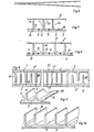
- the profiles are used on the one hand to form the heating gas flues, but on the other hand their webs placed on the water-carrying wall simultaneously form a largely condensation-preventing double wall on the water-carrying draft wall, wherein, as will be explained in more detail, a specifically metered heat transfer to the wall takes place.
- a specifically metered heat transfer to the wall takes place. which also has the effect during start-up processes during operation, particularly in the low-temperature area of the boiler, that the areas lying towards the fume cupboard side can heat up more quickly because of the lower heat transfer there, which counteracts or largely prevents the accumulation of condensate.
- the draft wall is rounded to form a tube or partial tube and closed with a longitudinal weld seam
- a multitude of heating gas flues with approximately triangular cross sections are created around the pot-like combustion chamber to be used later, each alternating with their distal base points against the combustion chamber and are directed against the wall.
- the rear cover 25 is provided with a flue gas outlet connection 26.
- the deflection chamber 27 is arranged in the tube formed by the wall on the burner side (burner not shown).
- the pot-like combustion chamber 28 sits in the free space between the heating gas flues 8, and the flue gas collecting chamber 28 'is located behind it.
- This boiler structure is not absolutely essential, just as the combustion chamber 28 must be cylindrical and the heating gas flues 8 must be arranged in a ring structure. Possibly.
- the walls of the combustion chamber can also be designed as water-carrying double walls, the interior of which is connected in a suitable manner to the other interior of the housing 22. This would be the case in which the heating gas flues 8 are delimited on both sides by water-cooled walls 3, 3 '.
- the sheet metal blanks for the rib profiles 1 look like they can be seen in FIG. 2 before they are deformed into U-profiles.
- the side slots are used to compensate for thermal expansion, but are not absolutely necessary.
- annular shell 30 can advantageously be arranged either completely or, as shown, in part freely projecting in the area of the flue gas collecting chamber 28 ', but for which it is essential that its inner edge is welded to the profiles 1, to ensure a flow of heat from the profiles into the shell 30, so that this can also heat up quickly.
- thermally connected in some areas is to be understood as the slot welding connection described above, but it is also possible, and this is also preferred because of the much lower expenditure, that the base webs 2 with, for example, a tungsten electrode (i.e. without the addition of additional welding material ) to be welded or melted.
- the attachment of longitudinal welding slots 16 of different sizes and distances can be omitted, and the attachment takes place in such a way that the tacking area or the resulting thermal bridge 5 becomes narrower or smaller from front to back. This can be accomplished easily and simply by means of a correspondingly regulated supply of current to the electrode, the weld or tack seam being interrupted in the sense of the different distances of the slots according to FIG. 2.
- the flow channels of the heating gas flue which are U-shaped in cross section are formed by rectangular profiles 10, i. H. two adjacent profiles 10 delimit a single channel.
- T-shaped profiles 11 according to FIG. 11 U-profiles can also be arranged at a distance from one another, the free surfaces of the wall 3 being covered with correspondingly wide intermediate webs 12 in order to avoid this Maintain double wall principle in all areas.
- 7, 8 are advantageously provided when pressing the profiles in the transition areas 13 of the legs 9 to the webs 2 profile crankings 14, which serve to accommodate the connecting edges 15 of adjacent webs 2 or the intermediate webs 12. This is advantageous in order to prevent arching when welding the webs 2 or the intermediate webs 12.
- the legs 9 of the profiles 10, 11, which can form the longitudinal ribs 1, as indicated in Fig. 7, at intervals with flag-like outbreaks conditions 19 are provided. 7, 8, the wall of the combustion chamber 28 which is not water-cooled in this case is designated by 3 ′′.
- the combustion chamber is water-cooled, there is (such boilers are known) an additional water-cooled wall 3 'with respect to the heating gas flue, which are also covered with the profiles described according to the same principle (FIG. 9) .
- the arrangement can be such that the longitudinal edges 17 of the opposing profiles 10, 11 end approximately in the same intermediate plane or protrude somewhat into the space 18 of the other profiles.
- an arrangement according to FIG. 9 is advantageously chosen such that the longitudinal edges 17 run closely above the welded points of the heat-conducting bridge 5.
- legs 9 can also have a common web 2 and the entire profile can also be designed, for example, as an extruded profile with a suitable wall thickness.
- the heating gas flues are shown in a straight extension, which of course can also be used in this form depending on the structural conditions on the boiler. It should be noted, however, that trains in this design, based on modern boiler designs, generally have more or less curved walls 3 and 3 ', respectively. that is, the exemplary embodiments shown also apply to such curved surfaces.
- An essential aspect of the entire heating gas train formation is, as described, to a certain extent draining heating gas-carrying areas to the extent that condensate formation is largely prevented, but on the other hand ensures that any condensate deposits are evaporated as quickly as possible when the boiler starts up again. Test boilers provided with such train designs and operated over a longer period of time have shown that these requirements are met absolutely satisfactorily.
Landscapes
- Engineering & Computer Science (AREA)
- Physics & Mathematics (AREA)
- Thermal Sciences (AREA)
- Chemical & Material Sciences (AREA)
- Combustion & Propulsion (AREA)
- Mechanical Engineering (AREA)
- General Engineering & Computer Science (AREA)
- Incineration Of Waste (AREA)
- Hydrogen, Water And Hydrids (AREA)
- Gas Burners (AREA)
- Chimneys And Flues (AREA)
Claims (8)
Priority Applications (1)
| Application Number | Priority Date | Filing Date | Title |
|---|---|---|---|
| AT84102993T ATE38091T1 (de) | 1983-03-21 | 1984-03-19 | Heizgaszugausbildung an heizungskesseln. |
Applications Claiming Priority (2)
| Application Number | Priority Date | Filing Date | Title |
|---|---|---|---|
| DE3310072 | 1983-03-21 | ||
| DE3310072A DE3310072C2 (de) | 1983-03-21 | 1983-03-21 | Heizgaszugausbildung an Heizungskesseln |
Publications (3)
| Publication Number | Publication Date |
|---|---|
| EP0120435A2 EP0120435A2 (fr) | 1984-10-03 |
| EP0120435A3 EP0120435A3 (en) | 1986-01-22 |
| EP0120435B1 true EP0120435B1 (fr) | 1988-10-19 |
Family
ID=6194097
Family Applications (1)
| Application Number | Title | Priority Date | Filing Date |
|---|---|---|---|
| EP84102993A Expired EP0120435B1 (fr) | 1983-03-21 | 1984-03-19 | Structure du parcours du gaz de chauffage dans une chaudière de chauffage |
Country Status (3)
| Country | Link |
|---|---|
| EP (1) | EP0120435B1 (fr) |
| AT (1) | ATE38091T1 (fr) |
| DE (2) | DE3310072C2 (fr) |
Families Citing this family (4)
| Publication number | Priority date | Publication date | Assignee | Title |
|---|---|---|---|---|
| DE3535341A1 (de) * | 1985-10-03 | 1987-04-09 | Viessmann Hans | Heizkessel fuer fluessige oder gasfoermige brennstoffe |
| AT399571B (de) * | 1992-02-21 | 1995-06-26 | Windhager Ohg Anton | Niedertemperatur-heizkessel für warmwasser-zentralheizungsanlagen u. dgl. |
| DE4400400A1 (de) * | 1994-01-08 | 1995-07-13 | Viessmann Werke Kg | Dreizug-Heizkessel |
| DE19622567A1 (de) * | 1996-06-05 | 1997-12-11 | Stahl Und Apparatebau Josef Sc | Einsatz für Heizkessel |
Family Cites Families (6)
| Publication number | Priority date | Publication date | Assignee | Title |
|---|---|---|---|---|
| DE1501676A1 (de) * | 1966-09-05 | 1969-10-23 | Variotherm S A | Innenrippenrohr fuer druckgas- oder druckoelbeheizte Heizkessel,insbesondere von Sammelheizungsanlagen |
| DE1778832A1 (de) * | 1968-06-11 | 1971-08-26 | Thyssen Industrie | Warmwasserkessel,insbesondere Heizungskessel |
| DE2852650A1 (de) * | 1978-12-06 | 1980-07-17 | Interliz Anstalt | Heizkessel fuer oel- bzw. gasfeuerung |
| DE2856338B2 (de) * | 1978-12-27 | 1981-01-22 | Hans 3559 Battenberg Viessmann | Heizungskessel für flüssige oder gasförmige Brennstoffe |
| DE2948864C2 (de) * | 1979-12-05 | 1982-10-14 | Hans 3559 Battenberg Vießmann | Heizungskessel für die Verbrennung von flüssigen oder gasförmigen Brennstoffen |
| DE3225762A1 (de) * | 1982-07-09 | 1984-01-12 | Hans Dr.h.c. 3559 Battenberg Vießmann | Heizungskessel |
-
1983
- 1983-03-21 DE DE3310072A patent/DE3310072C2/de not_active Expired
-
1984
- 1984-03-19 DE DE8484102993T patent/DE3474716D1/de not_active Expired
- 1984-03-19 AT AT84102993T patent/ATE38091T1/de active
- 1984-03-19 EP EP84102993A patent/EP0120435B1/fr not_active Expired
Also Published As
| Publication number | Publication date |
|---|---|
| ATE38091T1 (de) | 1988-11-15 |
| DE3310072C2 (de) | 1986-12-18 |
| DE3310072A1 (de) | 1984-10-04 |
| EP0120435A3 (en) | 1986-01-22 |
| DE3474716D1 (en) | 1988-11-24 |
| EP0120435A2 (fr) | 1984-10-03 |
Similar Documents
| Publication | Publication Date | Title |
|---|---|---|
| DE3007867A1 (de) | Katalytischer konverter fuer brennkraftmaschinenabgase | |
| DE2613186C3 (de) | Heizungskessel für flussige oder gasformige Brennstoffe | |
| EP0576963A1 (fr) | Récupérateur de chaleur pour montage dans l'enveloppe d'une chaudière | |
| DE3877694T2 (de) | Waermeaustauscher. | |
| EP0120435B1 (fr) | Structure du parcours du gaz de chauffage dans une chaudière de chauffage | |
| DE4232880A1 (de) | Dampferzeuger | |
| DE3205121C2 (de) | Heizungskessel | |
| EP0706010B1 (fr) | Appareil de chauffage avec arrangement de buses | |
| DE3205122C2 (de) | Heizungskessel | |
| DE3225762C2 (fr) | ||
| DE3205120C2 (de) | Wandausbildung für Heizungskessel zum Verbrennen flüssiger oder gasförmiger Brennstoffe | |
| EP0387627B1 (fr) | Chaudière | |
| EP0680586A1 (fr) | Chaudiere de chauffage | |
| EP0583574B1 (fr) | Chaudière à gaz | |
| EP0503146B1 (fr) | Tuyau plat de tirage pour gaz de chauffage pour chaudière à condensation | |
| EP0387628B1 (fr) | Chaudière | |
| EP0430061B1 (fr) | Chaudière de chauffage | |
| DE4229146C1 (de) | Gasheizkessel | |
| AT392025B (de) | Blechzuschnitt fuer die ausbildung eines in ein aussenrohr, insbesondere heizgaszugrohr, einsetzbaren innenrohres | |
| DE3144540C2 (de) | Feuerraumeinsatz | |
| EP0662592B1 (fr) | Chaudière à trois passages | |
| DE2245261C3 (de) | Lenkwandanordnung in einem Ausbrenn- oder Feuerraum eines Wärmetauschers | |
| DE7136314U (de) | Heizungskessel | |
| DE3310098A1 (de) | Heizungskessel | |
| DE3205119A1 (de) | Heizungskessel fuer fluessige oder gasfoermige brennstoffe |
Legal Events
| Date | Code | Title | Description |
|---|---|---|---|
| PUAI | Public reference made under article 153(3) epc to a published international application that has entered the european phase |
Free format text: ORIGINAL CODE: 0009012 |
|
| AK | Designated contracting states |
Designated state(s): AT BE CH DE FR GB IT LI LU NL SE |
|
| PUAL | Search report despatched |
Free format text: ORIGINAL CODE: 0009013 |
|
| AK | Designated contracting states |
Designated state(s): AT BE CH DE FR GB IT LI LU NL SE |
|
| 17P | Request for examination filed |
Effective date: 19860715 |
|
| 17Q | First examination report despatched |
Effective date: 19861209 |
|
| GRAA | (expected) grant |
Free format text: ORIGINAL CODE: 0009210 |
|
| AK | Designated contracting states |
Kind code of ref document: B1 Designated state(s): AT BE CH DE FR GB IT LI LU NL SE |
|
| PG25 | Lapsed in a contracting state [announced via postgrant information from national office to epo] |
Ref country code: GB Free format text: LAPSE BECAUSE OF NON-PAYMENT OF DUE FEES Effective date: 19881019 |
|
| REF | Corresponds to: |
Ref document number: 38091 Country of ref document: AT Date of ref document: 19881115 Kind code of ref document: T |
|
| REF | Corresponds to: |
Ref document number: 3474716 Country of ref document: DE Date of ref document: 19881124 |
|
| ET | Fr: translation filed | ||
| ITF | It: translation for a ep patent filed | ||
| PG25 | Lapsed in a contracting state [announced via postgrant information from national office to epo] |
Ref country code: LU Free format text: LAPSE BECAUSE OF NON-PAYMENT OF DUE FEES Effective date: 19890331 |
|
| GBV | Gb: ep patent (uk) treated as always having been void in accordance with gb section 77(7)/1977 [no translation filed] | ||
| PLBE | No opposition filed within time limit |
Free format text: ORIGINAL CODE: 0009261 |
|
| STAA | Information on the status of an ep patent application or granted ep patent |
Free format text: STATUS: NO OPPOSITION FILED WITHIN TIME LIMIT |
|
| 26N | No opposition filed | ||
| PG25 | Lapsed in a contracting state [announced via postgrant information from national office to epo] |
Ref country code: DE Effective date: 19891201 |
|
| ITTA | It: last paid annual fee | ||
| EAL | Se: european patent in force in sweden |
Ref document number: 84102993.7 |
|
| PGFP | Annual fee paid to national office [announced via postgrant information from national office to epo] |
Ref country code: BE Payment date: 19990303 Year of fee payment: 16 |
|
| PGFP | Annual fee paid to national office [announced via postgrant information from national office to epo] |
Ref country code: SE Payment date: 19990305 Year of fee payment: 16 |
|
| PGFP | Annual fee paid to national office [announced via postgrant information from national office to epo] |
Ref country code: CH Payment date: 19990326 Year of fee payment: 16 |
|
| PGFP | Annual fee paid to national office [announced via postgrant information from national office to epo] |
Ref country code: NL Payment date: 19990331 Year of fee payment: 16 Ref country code: FR Payment date: 19990331 Year of fee payment: 16 Ref country code: AT Payment date: 19990331 Year of fee payment: 16 |
|
| PG25 | Lapsed in a contracting state [announced via postgrant information from national office to epo] |
Ref country code: AT Free format text: LAPSE BECAUSE OF NON-PAYMENT OF DUE FEES Effective date: 20000319 |
|
| PG25 | Lapsed in a contracting state [announced via postgrant information from national office to epo] |
Ref country code: SE Free format text: LAPSE BECAUSE OF NON-PAYMENT OF DUE FEES Effective date: 20000320 |
|
| PG25 | Lapsed in a contracting state [announced via postgrant information from national office to epo] |
Ref country code: LI Free format text: LAPSE BECAUSE OF NON-PAYMENT OF DUE FEES Effective date: 20000331 Ref country code: CH Free format text: LAPSE BECAUSE OF NON-PAYMENT OF DUE FEES Effective date: 20000331 Ref country code: BE Free format text: LAPSE BECAUSE OF NON-PAYMENT OF DUE FEES Effective date: 20000331 |
|
| BERE | Be: lapsed |
Owner name: VIESSMANN HANS Effective date: 20000331 |
|
| PG25 | Lapsed in a contracting state [announced via postgrant information from national office to epo] |
Ref country code: NL Free format text: LAPSE BECAUSE OF NON-PAYMENT OF DUE FEES Effective date: 20001001 |
|
| EUG | Se: european patent has lapsed |
Ref document number: 84102993.7 |
|
| REG | Reference to a national code |
Ref country code: CH Ref legal event code: PL |
|
| PG25 | Lapsed in a contracting state [announced via postgrant information from national office to epo] |
Ref country code: FR Free format text: LAPSE BECAUSE OF NON-PAYMENT OF DUE FEES Effective date: 20001130 |
|
| NLV4 | Nl: lapsed or anulled due to non-payment of the annual fee |
Effective date: 20001001 |
|
| REG | Reference to a national code |
Ref country code: FR Ref legal event code: ST |