EP0120497B1 - Echangeur de chaleur à enveloppe et tubes - Google Patents
Echangeur de chaleur à enveloppe et tubes Download PDFInfo
- Publication number
- EP0120497B1 EP0120497B1 EP19840103378 EP84103378A EP0120497B1 EP 0120497 B1 EP0120497 B1 EP 0120497B1 EP 19840103378 EP19840103378 EP 19840103378 EP 84103378 A EP84103378 A EP 84103378A EP 0120497 B1 EP0120497 B1 EP 0120497B1
- Authority
- EP
- European Patent Office
- Prior art keywords
- tube
- heat exchanger
- fluid
- exchanger according
- members
- Prior art date
- Legal status (The legal status is an assumption and is not a legal conclusion. Google has not performed a legal analysis and makes no representation as to the accuracy of the status listed.)
- Expired
Links
Images


Classifications
-
- F—MECHANICAL ENGINEERING; LIGHTING; HEATING; WEAPONS; BLASTING
- F28—HEAT EXCHANGE IN GENERAL
- F28F—DETAILS OF HEAT-EXCHANGE AND HEAT-TRANSFER APPARATUS, OF GENERAL APPLICATION
- F28F9/00—Casings; Header boxes; Auxiliary supports for elements; Auxiliary members within casings
- F28F9/02—Header boxes; End plates
- F28F9/0229—Double end plates; Single end plates with hollow spaces
-
- F—MECHANICAL ENGINEERING; LIGHTING; HEATING; WEAPONS; BLASTING
- F28—HEAT EXCHANGE IN GENERAL
- F28D—HEAT-EXCHANGE APPARATUS, NOT PROVIDED FOR IN ANOTHER SUBCLASS, IN WHICH THE HEAT-EXCHANGE MEDIA DO NOT COME INTO DIRECT CONTACT
- F28D7/00—Heat-exchange apparatus having stationary tubular conduit assemblies for both heat-exchange media, the media being in contact with different sides of a conduit wall
- F28D7/16—Heat-exchange apparatus having stationary tubular conduit assemblies for both heat-exchange media, the media being in contact with different sides of a conduit wall the conduits being arranged in parallel spaced relation
- F28D7/163—Heat-exchange apparatus having stationary tubular conduit assemblies for both heat-exchange media, the media being in contact with different sides of a conduit wall the conduits being arranged in parallel spaced relation with conduit assemblies having a particular shape, e.g. square or annular; with assemblies of conduits having different geometrical features; with multiple groups of conduits connected in series or parallel and arranged inside common casing
- F28D7/1638—Heat-exchange apparatus having stationary tubular conduit assemblies for both heat-exchange media, the media being in contact with different sides of a conduit wall the conduits being arranged in parallel spaced relation with conduit assemblies having a particular shape, e.g. square or annular; with assemblies of conduits having different geometrical features; with multiple groups of conduits connected in series or parallel and arranged inside common casing with particular pattern of flow or the heat exchange medium flowing inside the conduits assemblies, e.g. change of flow direction from one conduit assembly to another one
-
- F—MECHANICAL ENGINEERING; LIGHTING; HEATING; WEAPONS; BLASTING
- F28—HEAT EXCHANGE IN GENERAL
- F28F—DETAILS OF HEAT-EXCHANGE AND HEAT-TRANSFER APPARATUS, OF GENERAL APPLICATION
- F28F1/00—Tubular elements; Assemblies of tubular elements
- F28F1/003—Multiple wall conduits, e.g. for leak detection
-
- F—MECHANICAL ENGINEERING; LIGHTING; HEATING; WEAPONS; BLASTING
- F28—HEAT EXCHANGE IN GENERAL
- F28F—DETAILS OF HEAT-EXCHANGE AND HEAT-TRANSFER APPARATUS, OF GENERAL APPLICATION
- F28F1/00—Tubular elements; Assemblies of tubular elements
- F28F1/08—Tubular elements crimped or corrugated in longitudinal section
-
- F—MECHANICAL ENGINEERING; LIGHTING; HEATING; WEAPONS; BLASTING
- F28—HEAT EXCHANGE IN GENERAL
- F28F—DETAILS OF HEAT-EXCHANGE AND HEAT-TRANSFER APPARATUS, OF GENERAL APPLICATION
- F28F9/00—Casings; Header boxes; Auxiliary supports for elements; Auxiliary members within casings
- F28F9/02—Header boxes; End plates
- F28F9/0219—Arrangements for sealing end plates into casing or header box; Header box sub-elements
-
- F—MECHANICAL ENGINEERING; LIGHTING; HEATING; WEAPONS; BLASTING
- F28—HEAT EXCHANGE IN GENERAL
- F28F—DETAILS OF HEAT-EXCHANGE AND HEAT-TRANSFER APPARATUS, OF GENERAL APPLICATION
- F28F9/00—Casings; Header boxes; Auxiliary supports for elements; Auxiliary members within casings
- F28F9/22—Arrangements for directing heat-exchange media into successive compartments, e.g. arrangements of guide plates
-
- F—MECHANICAL ENGINEERING; LIGHTING; HEATING; WEAPONS; BLASTING
- F28—HEAT EXCHANGE IN GENERAL
- F28F—DETAILS OF HEAT-EXCHANGE AND HEAT-TRANSFER APPARATUS, OF GENERAL APPLICATION
- F28F2275/00—Fastening; Joining
- F28F2275/20—Fastening; Joining with threaded elements
Definitions
- the present invention relates to a heat exchanger as described in the precharacterizing portion of claim 1.
- a heat exchanger of this kind is already known from EP-A-66425. Said heat exchanger comprising:
- the circumferential arms are spaced apart from the inner surface of the shell to define annular space such that a thin layer of the second heat exchange fluid circulates between the circumferential arms and the inner circumferential wall of the internal chamber.
- the second heat exchange fluid which is filled into the annular space and which is circulated between the outside of the circumferential arms and the inner side of the chamber acting as a thermal buffer to reduce temperature differential and temperature induced stresses in the shell and other parts of the heat exchanger so that an improved reliability is obtained. Furthermore, the reliability of the heat exchanger of the present invention is enhanced also because of the special construction of the tube members having double walls with cavities therebetween which are connected to the outside of the heat exchanger such that fractures of the tube members in case of a high temperature difference between the first and second fluid may be detected by leaking fluids.
- a second thermal exchange fluid such as a superheated refrigerant (i.e., ammonia) is applied through an inlet 18, comprising an aperture in a neck flange 46.
- the second fluid thereafter exits the heat exchanger through an outlet 20 in the neck flange 44.
- the outer shell 12 is shown partially broken in Fig. 1, exposing a substantially cylindrical inner chamber 22.
- the device as shown in Fig. 1 is not a complete assembly; as will be described in greater detail, and as illustrated in Figs. 2A and 2B, a plurality of heat exchange tubes 75 and a chamber-partitioning longitudinally extending baffle assembly 74 are positioned within the chamber 22 to effect a multi-pass, contraflow thermal exchange process, during operation, between the first and second fluids within the chamber 22 and the inner tubes 75 thereby facilitating the transfer of heat therebetween.
- the additional assemblies for such purpose are illustrated in subsequent drawing figures.
- neck flanges 44 and 46 are affixed to axially opposed ends of the shell 12 as by welding or an equivalent process.
- the neck flanges 44, 46 are conveniently identical in structure, each including a port 20, 18 respectively and so forth, but are rotally offset 72° from each other prior to affixation to the shell.
- the assemblies 14, 16 respectively comprise a sandwich-like arrangement of elements joined to neck flanges 44 and 46 by a plurality of bolts 48 peripherally arranged about the assemblies 14 and 16 and threadedly engaged to nuts 50.
- the inlet end assembly 14 includes an end cap 24, a center pressure flange 32 and an inner tube sheet 40.
- a similar outlet end assembly arrangement comprises end cap 26, center pressure flange 34, and inner tube sheet 42.
- the neck flange 44 conveniently includes exit port 20, through which the second heat transfer fluid exits, as well as a port 85 for pressure relief valve 86. Both ports communicate with interior chamber 22 as subsequently described in greater detail.
- the ports may be formed as part of a molding process by which the flange is conveniently made, providing a less expensive alternative to drilling the ports in the shell and welding to the shell threaded fittings.
- Fig. 3 is a cross-section of the heat exchanger 10 taken along line 3-3 in Fig. 1.
- the baffle assembly 74 is seen to be formed from five interlocking baffle members 76, 78, 80, 82 and 84 which may be simply and economically formed from, for example, aluminum via an extrusion process.
- the baffle member 76 it is seen to comprise a radial arm 134 and a circumferential arm 132 that corresponds generally to the inner circumference of the shell 12.
- the circumferential arm 132 and radial arm 134 extend axially through the chamber 22. As shown in Fig. 3, the circumferential arm 132 extends generally circumferentially away from the radial arm 134 and terminates in a hook-like leg portion 140.
- the junction of the radial and circumferential arms includes a socket 136 having a complimentary shape to leg 140 so that it captures a similar leg 138 of adjacent baffle member 84.
- the leg 140 similarly captured by the socket of neighboring baffle member 78.
- baffle member 76 lies interjacent baffle members 84 and 78, member 84 being adjacent in a clockwise direction and member 78 being adjacent counterclockwise.
- the radially inner portion of the radial arm 134 terminates in a hook-shape adapted to interlock with the corresponding appendage of the counter- clockwise adjacent baffle member 78.
- the appendage 137 is adapted to interlock with the terminus of the clockwise adjacent radial arm of baffle member 84. As shown in Fig. 3, each radial arm butts against its adjacent neighbors and interlocks.
- baffle assembly 74 a first baffle member 84 is placed in the shell 12.
- the distal end of the leg (e.g., 138) of the first baffle member is inserted into the proximal end of the socket (e.g., 136) of the second member while simultaneously inserting the hooked appendage 137 of the second member into the appendage of the first.
- the second member is slid relatively axially into the chamber so that there is full engagement between the terminus/appendage and socket/leg, which are shaped such that the members cannot separate unless slid axially.
- Each of the third through fifth members is thereafter slid axially into place, and the resulting baffle assembly is slid into the chamber 22 as hereinafter described in detail.
- the radially extending arms are slightly oversized to provide a radially directed compression of the assembly, effecting a seal where the radial arms abut.
- the circumferential arms of the baffle members include radially outward extending legs 76a, 78a, 80a, 82a and 84a which maintain a clearance of approximately 1 mm between the radially outer surface of the baffle assembly and the inner wall of the shell 12.
- Fig. 3 additionally illustrates a cross-section of the inlet 18 for the second heat exchange fluid and tubes 75 for conducting the first heat exchange fluid.
- the second heat exchange fluid enters the baffle sector I defined by baffle member 84 and radial arm 134, and flows axially out of the drawing.
- the inlet 18 includes an aluminum sleeve 71 which is passed through the aperture in the shell 12 into inlet 18 and has been expanded into position. Accordingly, the incoming second fluid cannot pass into the space between the baffle and the inside wall of the shell 12. For reasons which will be explained subsequently, no corresponding expanded sleeve is associated with the outlet 20 or pressure relief port 85 (Fig. 1), thereby enabling a portion of egressing second fluid to fill the space 145 in operation.
- a "sleeve” may be drawn out of the baffle assembly wall: specifically, out of circumferential arm 147.
- the inlet hole is punched through the arm 147 and the material drawn outward to form a funnel-like conduit integral with the baffle member.
- the punched baffle member is placed within the chamber 22 first by locating the drawn hole into the hole of inlet 18 of the neck flange 46. The remaining baffle members are then slid in as described earlier.
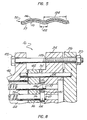
- Fig. 4 is an enlarged longitudinal partion section of the assembled end assembly 14 illustrating, in part, a representative of one of the heat exchange tubes.
- Fig. 5 is an enlarged sectional view of a portion of expanded surface tubing taken about section line 5 in Fig. 4.
- Fig. 8 is a port section of the assembled end assembly 16 illustrating in part a representative of one of the heat exchange tubes.
- the tubing 75 generally comprises an outer skin 96 and an inner skin 57 pressed together along a helical area of contact so that a gap or cavity 110 effectively spirals the length of the tube between adjacent spiral contact areas. If, for example, the outer skin 96 of a tube 75 in Sector I (Fig. 3) fractures, the second fluid in Sector I will enter the spiral cavity 110 and, in accordance with the invention, as subsequently described, such fracture will be detected by the venting of such fluid from within the cavity 110 to atmosphere. Similarly, when the inner skin 57 is breached, the first fluid will enter the spiral cavity 110 and will thereafter be vented to atmosphere in accordance with the invention as subsequently described.
- the configuration of tube 75 has been designed to improve the heat transfer coefficient over conventional enhanced surface tubes. This improvement is achieved by providing a relatively wide groove where the outer skin 96 and the inner skin 57 are pressed together, yielding greater area of metal contact 122. Additionally, by increasing the distance 124 between the grooves to allow a thicker wetted surface to form, an increased heat transfer coefficient is provided. Because enhanced surface tubing significantly increases the heat transfer of a particular tube diameter in heat exchange equipment, a particular configuration is provided wherein the controlling parameters are optimized. In particular, a groove width 122 of approximately 3,1 mm and depth of approximately 2,4 mm assures good turbulation of the fluids on both sides of the tube while maximizing heat transfer without collapsing the tube during manufacture. The pitch 124 of the optimal tube is found to be 14,3 mm. A gap 110 of 76 urn was employed to meet venting regulations but should be kept at a minimum to ensure maximum heat transfer.
- the inner tube sheet 42 is first mounted onto the neckflange 46 by means of locating dowels 70' protruding from the flange and receiving holes 38 in the tube sheet 42.
- the dowels and dowel-receiving holes are similar to dowel 70 and holes 56 associated with tube sheet40 of the inlet assembly and illustrated in Fig. 2A.
- the tube sheet 42 which is similar to plate 40 (Fig. 2A) includes a pattern of holes sized to accommodate the outer skins 96 of the tubes 75.
- the hole pattern corresponds to the pattern of the tubes 75 shown in Fig. 3.
- FIG. 8 a fragmentary sectional view of the outlet end of the heat exchanger 10.
- Each of the tubes 75 to be inserted into chamber 22 through a respective one of the holes in the inner tube sheet 42, includes a bushing 104 which has been inserted over the end of the tube.
- the bushing 104 includes a through-hole having a stepped wall 104a such that the larger internal diameter portion of the bushing engages the outer skin 96 of tube 75, while the smaller diameter portion of the bushing engages the inner skin 57 of tube 75.
- a general swedging tool may then be inserted into the tube, as is known in the art, to expand the tubes within the bushing and thereby effect respective seals between the bushing and the inner and the outer skins, with the gap 110 between the inner and outer skins being sealed against the step 104a of the internal bushing wall.
- each bushing contacts a gasket similar to gasket 67 against the outer face of the plate 42.
- the neck flange 44 is shown to include a number of peripheral apertures 33 and a longitudinally extending, peripheral dowel 70.
- the dowel 70 is adapted to pass through location holes respectively formed in the components of end assembly 14 when the components are mounted onto the flange 44.
- a gasket assembly comprising a tube sheet 40 interjacent two gaskets 68, 69 is mounted onto the flange 44.
- the tube sheet and gasket 68 include aligned hole patterns corresponding to the layout of tube holes 95 so that the tubes 75 extend outward therethrough.
- the gasket assembly and the corresponding gasket assembly of outlet assembly 16 define the ends of chamber 22 for the second heat transfer fluid.
- each bushing 41 includes a pair of O-rings 102, 103 for forming a tube expansion region 43 communicating with gap 110 in tube 75.
- a hole 111 which connects to gap 110 to allow the tube to vent to atmosphere.
- gasket 67 is fitted over the protruding inner tube 57 of tube 75.
- a pressure flange 32 is then correctly oriented via dowel 70 and assembled onto the neck flange 44.
- the axially inner face of pressure flange 32 butts against the gasket 67 which is against the outer face of the bushings 41, resulting in an outer annular portion 32a which circumvents the protruding bushings 41 and which is adapted to sealingly contact the gaskets 67 and 68 to define a vent chamber 45 between the flange 32 and tube sheet 40.
- the vent passage is completed with a vent hole 47 in pressure flange annular portion 32a.
- the aforedescribed arrangement is directed toward preventing the contamination of one of the heat exchange fluids by the other. Should the outer skin 96 of a tube 75 fracture and permit the second fluid to enter and travel along helical gap 110, the fluid will enter region 43 pass through hole 111 then to atmosphere through hole 47. The second fluid will not escape from gap 110 at the outlet assembly 16 since the expansion of tube 75 into bushing 104 at that end has sealed that bushing across the gap.
- bushing 41 includes a through-hole 111 through which any fluid in gap 110 will escape.
- the escaping fluid falls downward through chamber 45 and out of the end assembly via through-hole 47 in the bottom periphery of the pressure flange 32 and is detected by means hereinafter set forth so that the tube 75 can be replaced before a subsequent fracture in inner skin 57 or other event permits a mixing of the first and second fluids.
- a fracture of the inner skin 57 results in first fluid being restricted to region 43 and escaping via hole 111 and 47.
- the pressure flange 32 additionally comprises a central portion 32b relatively recessed from the gasket-contacting surface of the annular portion 32a.
- the recessed portion contains a pattern of through-passages 95 located in alignment with the axially extending inner sleeves 57 that protrude from bushings 41.
- the axially inward face of the recessed portion 32b surrounds each passage 95 thereby sealingly contacts the axially outward face of the respective bushing against gasket 67.
- the inner sleeves 57 extend into, but do not protrude from the axially outward side of, passages 95.
- the axially outer face of the pressure flange 32 includes an end baffle arrangement 28 comprising annular portion 28a circumscribing the through-holes 95 together with a generally Y-shaped portion comprising generally radially extending bars 52a, b, and c.
- the bars 52a, b, and c and annular portion 28a are adapted to sealingly contact the interior face of end cap 24 via a gasket 29 and to thereby form a series of pressure chambers, as better explained by reference to Figs. 6 and 7.
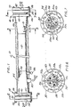
- Figs. 6 and 7 are cross-sectional views of portions of the inlet and outlet end assemblies taken along the lines 6-6 and 7-7, respectively, of Fig. 1. As can be seen, the end assemblies are substantially similar.
- the plurality of bolt receiving holes 149 is provided about the outer periphery of pressure flange 32, 34.
- End baffle 28, 30 illustrated in Figs. 6 and 7 as comprising an annular steel portion 28a, 30a, with radial vane arrangements 52a, b, c, and 59a, b, c.
- the relative orientation of the vanes 28, 30 is arranged by a 72° rotational offset.
- Apertures 56, 38 in the annular portion of the baffles are provided for insertion about positioning dowels 70, 70' to provide the correct relative orientations of the vane arrangements within the end assemblies 14 and 16. Accordingly, the welding of neck flange 46 onto shell 12 at a rotational offset of 72° from the orientation of neck flange 44 permits identical components to be used in end assemblies 14, 16 except for bushings 41, 104.
- the end baffles 28, 30 vanes define pressure chambers in the end assemblies 14, 16 that provide a fluid flow continuum for reversing the direction of the first heat exchange fluid within the thermal exchange tubes.
- the dashed circles 54 and 62 indicate the locations of the inlet port 54 and the outlet port 62 with respect to the vane arrangements 28 and 30 respectively.
- the radial fins of each arrangements subtend two obtuse and acute angles. In an actual reduction to practice of the invention, an acute angle of 72° and obtuse angles of 144° were employed.
- the through passages 95 which the ends of the inner tube sleeves 57 engage into are shown in Figs. 6 and 7.
- the axially outer faces 28a, 30a are illustratively divided into in 72° segments denoted "A" through “E” and “A"' through “E”', respectively.
- the three radial vanes of each end baffle cooperate with the interior of the respective end cap 24, 26 to define three end chambers at each end of the heat exchanger.
- the flow of the first heat exchange fluid through the heat exchanger occurs in the following sequence: the fluid enters the heat exchanger 10 under pressure at inlet port 54 (Fig.
- the fluid can only enter the channels within segment D for transmission once again through the heat exchange chamber 22, and so forth.
- the end of one inner sleeve 57 within each of the defined segments of the end pressure chambers has been identified according to the direction of first fluid flow in the tube nest of that segment, a "dot” indicating fluid flow emerging from the plane of the paper and a "cross” indicating flow into the plane of the paper.
- a multipass fluid flow path is established for the first fluid through the heat transfer chamber 22.
- Fig. 3 the second fluid has been mentioned as entering section I of chamber 22 via inlet 18.
- Radial arms 134 are sealed against tube sheet 40, (better appreciated by reference to Fig. 2) and therefore cannot pass out of section I via the #1 fluid outlet end 16 of the exchanger.
- the second fluid accordingly flows towards the #1 fluid inlet end 14 until it reaches the interface of segment I and inner tube sheet 40. While the entire radially directed length of radial arm 134 is sealed against tube sheet 40, a portion of the axially remote end of radial arm 134 terminates short of the tube sheet permitting the second fluid to flow around the remote end of arm 134 and back towards the outlet end 14 (Fig. 1) via segment II (Fig. 3) of the chamber 22.
- baffle 78 terminates short of tube sheet 42, permitting the second fluid to pass into section III and flow towards the inlet end 14 (Fig. 1). From section III, the second fluid similarly flows through section IV and V egressing from the chamber 22 via outlet 20 at the completion of its pass through section V.
- a generally "C" shaped notch 210 cooperates with the tube sheet to form a conduit between adjacent segment, while the remaining radial lengths of the arms seal against the tube sheet.
- Fig. 3 displays a "dot” and "cross” symbol in a representative tube 75 of each nest to indicate the flow direction of first fluid in the respective segment.
- a “dot” indicates flow out of the plane of the page, while a “cross” indicates a flow into the plane.
- the flow direction of the second fluid is shown by a like symbol in each segment exterior to the tube 75 therein.
- the first and second fluids flow in opposite directions in each of the sections I-V.
- the first fluid will be at one temperature extreme (e.g., coldest) in section V, and progressively hotter (to follow the example) in each successive section IV-I as it flows through successive segments in a clockwise direction.
- the second fluid is at its temperature extreme (e.g., hottest) in section I, wherein the first fluid is hottest flows through successive segments in a counter-clockwise direction, and exits from section V, at its coldest, where the first liquid is also at its coldest.
- the two fluids continue to exchange heat unidirectionally throughout their counterflow in the heat exchanger.
- a thin circulating layer of second fluid is provided in the annular, axially extending space 145 between the circumferential arms of the baffle assembly and the inner circumferential wall of chamber 22.
- the space 145 is, as previously mentioned, provided by legs 76a, 78a, 80a, 82a and 84a which support the baffle assembly radially inward from the chamber 22 wall.
- the outlet 20 for the second fluid does not include a sleeve such as sleeve 71 of inlet 18, thereby permitting egressing second fluid to "leak" into, and fill, the space. Accordingly, the temperature of the shell is maintained generally uniform about its circumference.
- the second fluid (assumed to be refrigerant for illustrative purposes) in segment is warmest, is successively colder in segments II-V. Accordingly, the second fluid in space 145 radially adjacent to section I will be warmer, and less dense, than the second fluid in space 145 radially adjacent to section V. Accordingly, the second fluid in space 145 will tend to rise counter- clockwise in Fig. 3. Once the second fluid reaches the 12 o'clock position, gravity causes it to flow downward, completing the loop. Once the space is filled, no additional fluid enters the space, and fluid in the space will slowly circulate counter- clockwise to minimize temperature-induced stresses in the shell.
- Assembly of the heat exchanger 10 is completed by positioning the end caps 24, 26 onto the neck flange 44, 46.
- Bolts 48 are inserted through the apertures 33 in both neck flanges with their heads pointed towards the opposite of the heat exchanger.
- Nuts 50 are then tightened onto the bolts to secure the end assemblies 14, 16.
- the holes 149 in the pressure flanges 32, 34 are threaded to engage the bolts 48. Accordingly, the removal of nuts 50 permits disassembly of the end caps 24, 26 for visual inspection of the end baffles without breaking the seal between the pressure flanges 32, 34 and respective neck flanges 44, 46.
- the tubes 75 may accordingly be inspected through apertures 95 without the voiding of the second fluid in chamber 22. This is particularly advantageous when the second fluid is a refrigerant.
- the end assemblies can be easily disassembled.
- the expanded tube/bushing combination requiring replacement can simply be axially slid out of the heat exchanger with the O-rings of the bushing 41 permitting the axial sliding movement.
- a replacement bushing/ expanded tube combination can then be axially slid through the inner tube sheet 33, chamber 22, and the bushing 41 refitted to the replaced tube.
- end assembly 16 (Fig. 8), it will be appreciated that any leakage of second heat transfer fluid through gaskets associated with the inner tube sheet 42 or the pressure flange 34 will be drawn into vent chamber 151 and vent to atmosphere by the same method as end assembly 14.
- Another feature of the described embodiment is directed to the temperature-induced dimensional changes in the tubes 75.
- higher outlet temperatures of the first fluid have been provided using a five segment chamber with successive counterflowing first and second fluids to increase surface contact time. Because the segments I-V represent different temperature zones within the heat exchanger, the tubes 75 of each segment will expand to a greater or lesser degree than the tubes of the remaining segments.
- each tube 75 to freely expand to the extent required, thereby meeting design codes governing such heat exchangers.
- the tube ends in end assembly 16 are relatively fixed owing to the securing of bushes 104 into which the tubes have been expanded.
- the other end of the tube 75 is permitted to "float" axially so that temperature-induced changes in standardized tube length may be accommodated during operation of the heat exchanger.
- outer skin 96 of tube 75 may slide axially within the 0-ring without loss of sealing contact therebetween.
- inner skin 57 may slide axially within the 0-ring without loss of sealing contact between the two. Because skin 57 and skin 96 are joined together by metal contact area 122, tube 75 is one tube of a tube within a tube design and skins 57 and 96 move simultaneously.
Landscapes
- Engineering & Computer Science (AREA)
- Physics & Mathematics (AREA)
- Thermal Sciences (AREA)
- Mechanical Engineering (AREA)
- General Engineering & Computer Science (AREA)
- Geometry (AREA)
- Heat-Exchange Devices With Radiators And Conduit Assemblies (AREA)
Claims (20)
Applications Claiming Priority (4)
| Application Number | Priority Date | Filing Date | Title |
|---|---|---|---|
| US47923483A | 1983-03-28 | 1983-03-28 | |
| US479234 | 1983-03-28 | ||
| US58297584A | 1984-02-23 | 1984-02-23 | |
| US582975 | 1984-02-23 |
Related Child Applications (2)
| Application Number | Title | Priority Date | Filing Date |
|---|---|---|---|
| EP87113723.8 Division-Into | 1984-03-27 | ||
| EP19870113723 Division-Into EP0259895B1 (fr) | 1983-03-28 | 1984-03-27 | Echangeur de chaleur tubulaire |
Publications (3)
| Publication Number | Publication Date |
|---|---|
| EP0120497A2 EP0120497A2 (fr) | 1984-10-03 |
| EP0120497A3 EP0120497A3 (en) | 1985-10-23 |
| EP0120497B1 true EP0120497B1 (fr) | 1989-07-26 |
Family
ID=27046177
Family Applications (2)
| Application Number | Title | Priority Date | Filing Date |
|---|---|---|---|
| EP19870113723 Expired EP0259895B1 (fr) | 1983-03-28 | 1984-03-27 | Echangeur de chaleur tubulaire |
| EP19840103378 Expired EP0120497B1 (fr) | 1983-03-28 | 1984-03-27 | Echangeur de chaleur à enveloppe et tubes |
Family Applications Before (1)
| Application Number | Title | Priority Date | Filing Date |
|---|---|---|---|
| EP19870113723 Expired EP0259895B1 (fr) | 1983-03-28 | 1984-03-27 | Echangeur de chaleur tubulaire |
Country Status (4)
| Country | Link |
|---|---|
| EP (2) | EP0259895B1 (fr) |
| CA (1) | CA1264735A (fr) |
| DE (2) | DE3479153D1 (fr) |
| DK (1) | DK168684A (fr) |
Families Citing this family (11)
| Publication number | Priority date | Publication date | Assignee | Title |
|---|---|---|---|---|
| EP0245465A4 (fr) * | 1985-11-05 | 1988-04-18 | Tui Ind | Echangeur a faisceaux. |
| FR2603693B1 (fr) * | 1986-09-05 | 1990-03-30 | Toshiba Kk | Echangeur de chaleur tubulaire a calandre |
| US4870734A (en) * | 1987-04-03 | 1989-10-03 | Tui Industries | Method of manufacturing high efficiency heat exchange tube |
| US5004042A (en) * | 1989-10-02 | 1991-04-02 | Brunswick Corporation | Closed loop cooling for a marine engine |
| DE3938254A1 (de) * | 1989-11-17 | 1991-05-23 | Behr Gmbh & Co | Oelkuehler |
| EP0644394A1 (fr) * | 1993-09-21 | 1995-03-22 | Proizvodstvennoe Obiedinenie "Chernovitsky Mashinostroitelny Zavod" | Echangeur de chaleur |
| US10190765B2 (en) | 2013-09-30 | 2019-01-29 | Conleymax Inc. | Heat exchanger |
| CN107449314B (zh) * | 2017-07-24 | 2019-02-22 | 青岛德固特节能装备股份有限公司 | 一种金属套浮管密封结构 |
| CN112503976B (zh) * | 2020-12-01 | 2024-11-19 | 佛山神威热交换器有限公司 | 一种具有换热介质分流减压功能的旋流式换热器 |
| CN117470000B (zh) * | 2023-12-26 | 2024-02-23 | 山东齐成石油化工有限公司 | 一种环保型石油化工用高效换热器 |
| CN118582989B (zh) * | 2024-08-06 | 2024-10-22 | 江苏民生重工有限公司 | 一种冷凝热交换装置 |
Family Cites Families (15)
| Publication number | Priority date | Publication date | Assignee | Title |
|---|---|---|---|---|
| GB208822A (en) * | 1922-10-06 | 1924-01-03 | Harry Francis Jackson Thompson | Improvements in or relating to air coolers |
| GB315934A (en) * | 1928-05-05 | 1929-07-25 | Henry Kirk | Improvements in and connected with tube radiators |
| US2762611A (en) * | 1952-02-28 | 1956-09-11 | Pfaudler Co Inc | Tubular heat exchangers |
| DE1064966B (de) * | 1953-12-23 | 1959-09-10 | Zellwolle Lenzing Ag | Roehrenwaermeaustauscher mit Rohrboeden, bestehend aus einer elastischen Platte und beiderseits anliegenden starren Platten |
| US3181606A (en) * | 1962-07-09 | 1965-05-04 | Heat Exchangers Res And Dev Co | Heat exchanger bundle |
| FR1537988A (fr) * | 1967-07-12 | 1968-08-30 | Danto Rogeat & Co | Perfectionnement aux échangeurs thermiques tubulaires |
| US3490521A (en) * | 1968-03-12 | 1970-01-20 | Westinghouse Electric Corp | Tube and shell heat exchanger |
| DE2111387A1 (de) * | 1971-03-03 | 1972-09-07 | Karl Fischer App U Rohrleitung | Rohrbuendel-Waermeaustauscher |
| FR2186120A5 (fr) * | 1972-05-26 | 1974-01-04 | Nalet Jean | |
| US4105065A (en) * | 1977-03-07 | 1978-08-08 | Ecodyne Corporation | Heat exchanger |
| GB2047400B (en) * | 1979-04-25 | 1983-11-30 | Blythe & Co Ltd William | Heat exchanger |
| DE2930577A1 (de) * | 1979-07-27 | 1981-02-12 | Wiessner Gmbh | Waermetauscher |
| AU7757581A (en) * | 1980-11-19 | 1982-05-27 | United Energy Technologies Inc. | Enhanced surface tubing |
| NZ198291A (en) * | 1981-05-22 | 1984-10-19 | Energy Resources International | Fixed tube sheet exchanger with at least three contraflow shell and tube passes |
| DE3214271A1 (de) * | 1982-04-17 | 1982-12-09 | Peter 8137 Berg Flögel | Hochdruck-waermepumpe |
-
1984
- 1984-03-27 EP EP19870113723 patent/EP0259895B1/fr not_active Expired
- 1984-03-27 EP EP19840103378 patent/EP0120497B1/fr not_active Expired
- 1984-03-27 DE DE8484103378T patent/DE3479153D1/de not_active Expired
- 1984-03-27 DE DE8787113723T patent/DE3482777D1/de not_active Expired - Lifetime
- 1984-03-27 DK DK168684A patent/DK168684A/da not_active IP Right Cessation
- 1984-03-28 CA CA000450745A patent/CA1264735A/fr not_active Expired
Also Published As
| Publication number | Publication date |
|---|---|
| CA1264735A (fr) | 1990-01-23 |
| DE3479153D1 (en) | 1989-08-31 |
| EP0120497A2 (fr) | 1984-10-03 |
| EP0120497A3 (en) | 1985-10-23 |
| DK168684A (da) | 1984-11-09 |
| EP0259895B1 (fr) | 1990-07-18 |
| EP0259895A1 (fr) | 1988-03-16 |
| DK168684D0 (da) | 1984-03-27 |
| DE3482777D1 (de) | 1990-08-23 |
Similar Documents
| Publication | Publication Date | Title |
|---|---|---|
| US4871014A (en) | Shell and tube heat exchanger | |
| US4858681A (en) | Shell and tube heat exchanger | |
| US4017102A (en) | Jacket construction for pipe coupling | |
| US5323849A (en) | Corrosion resistant shell and tube heat exchanger and a method of repairing the same | |
| US5649589A (en) | Safety annular heat exchanger for incompatible fluids | |
| RU2137078C1 (ru) | Теплообменник | |
| HU200833B (en) | Heat-exchanger built-up from modules for climating buildings | |
| WO1987002763A1 (fr) | Echangeur a faisceaux | |
| US6341650B2 (en) | Heat exchanger | |
| US5170841A (en) | Multi-way quick action coupling device particularly for motor vehicle engine cooling circuits | |
| EP0259895A1 (fr) | Echangeur de chaleur tubulaire | |
| US20100139900A1 (en) | Gas Turbine Regenerator Apparatus and Method of Manufacture | |
| EP0628779B1 (fr) | Echangeur de chaleur | |
| US20180003444A1 (en) | Heat exchanger | |
| CN212931081U (zh) | 一种u形管换热器 | |
| US5178208A (en) | Multi-way quick action coupling device particularly for motor vehicle engine cooling circuits | |
| US4986349A (en) | Heat exchanger | |
| EP0764810B1 (fr) | Isolation et/ou système de chauffage et/ou système de réfrigération avec éléments préfabriqués séparés des tuyaux | |
| WO1993003318A1 (fr) | Echangeur de chaleur du type a baïonnette | |
| EP0113344B1 (fr) | Echangeurs de chaleur et leur procede de construction | |
| EP0605718B1 (fr) | Echangeur de chaleur avec une plaque de facade | |
| CN112595151B (zh) | 一种管壳式多程换热器 | |
| JPS59189290A (ja) | 熱交換器 | |
| KR102013645B1 (ko) | 열교환기 | |
| JPH0717954Y2 (ja) | 熱交換器 |
Legal Events
| Date | Code | Title | Description |
|---|---|---|---|
| PUAI | Public reference made under article 153(3) epc to a published international application that has entered the european phase |
Free format text: ORIGINAL CODE: 0009012 |
|
| AK | Designated contracting states |
Designated state(s): BE DE FR GB IT NL SE |
|
| PUAL | Search report despatched |
Free format text: ORIGINAL CODE: 0009013 |
|
| RAP1 | Party data changed (applicant data changed or rights of an application transferred) |
Owner name: TUI INDUSTRIES INC. |
|
| RIN1 | Information on inventor provided before grant (corrected) |
Inventor name: SULZBERGER, KEVIN |
|
| AK | Designated contracting states |
Designated state(s): BE DE FR GB IT NL SE |
|
| RAP1 | Party data changed (applicant data changed or rights of an application transferred) |
Owner name: TUI INDUSTRIES INC. |
|
| 17P | Request for examination filed |
Effective date: 19860417 |
|
| 17Q | First examination report despatched |
Effective date: 19860825 |
|
| D17Q | First examination report despatched (deleted) | ||
| GRAA | (expected) grant |
Free format text: ORIGINAL CODE: 0009210 |
|
| AK | Designated contracting states |
Kind code of ref document: B1 Designated state(s): BE DE FR GB IT NL SE |
|
| REF | Corresponds to: |
Ref document number: 3479153 Country of ref document: DE Date of ref document: 19890831 |
|
| ET | Fr: translation filed | ||
| RAP2 | Party data changed (patent owner data changed or rights of a patent transferred) |
Owner name: TUI INDUSTRIES |
|
| ITF | It: translation for a ep patent filed | ||
| NLT2 | Nl: modifications (of names), taken from the european patent patent bulletin |
Owner name: TUI INDUSTRIES TE ANAHEIM, CALIFORNIE, VER. ST. V. |
|
| PG25 | Lapsed in a contracting state [announced via postgrant information from national office to epo] |
Ref country code: SE Effective date: 19900328 |
|
| PGFP | Annual fee paid to national office [announced via postgrant information from national office to epo] |
Ref country code: DE Payment date: 19900329 Year of fee payment: 7 |
|
| PGFP | Annual fee paid to national office [announced via postgrant information from national office to epo] |
Ref country code: FR Payment date: 19900330 Year of fee payment: 7 |
|
| PG25 | Lapsed in a contracting state [announced via postgrant information from national office to epo] |
Ref country code: BE Effective date: 19900331 |
|
| PGFP | Annual fee paid to national office [announced via postgrant information from national office to epo] |
Ref country code: GB Payment date: 19900331 Year of fee payment: 7 |
|
| PLBE | No opposition filed within time limit |
Free format text: ORIGINAL CODE: 0009261 |
|
| STAA | Information on the status of an ep patent application or granted ep patent |
Free format text: STATUS: NO OPPOSITION FILED WITHIN TIME LIMIT |
|
| 26N | No opposition filed | ||
| BERE | Be: lapsed |
Owner name: TUI INDUSTRIES INC. Effective date: 19900331 |
|
| PG25 | Lapsed in a contracting state [announced via postgrant information from national office to epo] |
Ref country code: NL Effective date: 19901001 |
|
| NLV4 | Nl: lapsed or anulled due to non-payment of the annual fee | ||
| PG25 | Lapsed in a contracting state [announced via postgrant information from national office to epo] |
Ref country code: GB Effective date: 19910327 |
|
| GBPC | Gb: european patent ceased through non-payment of renewal fee | ||
| PG25 | Lapsed in a contracting state [announced via postgrant information from national office to epo] |
Ref country code: FR Effective date: 19911129 |
|
| PG25 | Lapsed in a contracting state [announced via postgrant information from national office to epo] |
Ref country code: DE Effective date: 19920101 |
|
| REG | Reference to a national code |
Ref country code: FR Ref legal event code: ST |
|
| EUG | Se: european patent has lapsed |
Ref document number: 84103378.0 Effective date: 19910110 |