EP0120505A2 - Fenêtre ou porte permettant l'ouverture à l'un ou l'autre des deux bords opposés - Google Patents
Fenêtre ou porte permettant l'ouverture à l'un ou l'autre des deux bords opposés Download PDFInfo
- Publication number
- EP0120505A2 EP0120505A2 EP84103481A EP84103481A EP0120505A2 EP 0120505 A2 EP0120505 A2 EP 0120505A2 EP 84103481 A EP84103481 A EP 84103481A EP 84103481 A EP84103481 A EP 84103481A EP 0120505 A2 EP0120505 A2 EP 0120505A2
- Authority
- EP
- European Patent Office
- Prior art keywords
- window
- stop
- frame
- locking
- tilt
- Prior art date
- Legal status (The legal status is an assumption and is not a legal conclusion. Google has not performed a legal analysis and makes no representation as to the accuracy of the status listed.)
- Withdrawn
Links
Images




Classifications
-
- E—FIXED CONSTRUCTIONS
- E05—LOCKS; KEYS; WINDOW OR DOOR FITTINGS; SAFES
- E05D—HINGES OR SUSPENSION DEVICES FOR DOORS, WINDOWS OR WINGS
- E05D15/00—Suspension arrangements for wings
- E05D15/48—Suspension arrangements for wings allowing alternative movements
- E05D15/50—Suspension arrangements for wings allowing alternative movements for opening at either of two opposite edges
-
- E—FIXED CONSTRUCTIONS
- E05—LOCKS; KEYS; WINDOW OR DOOR FITTINGS; SAFES
- E05C—BOLTS OR FASTENING DEVICES FOR WINGS, SPECIALLY FOR DOORS OR WINDOWS
- E05C9/00—Arrangements of simultaneously actuated bolts or other securing devices at well-separated positions on the same wing
- E05C9/06—Arrangements of simultaneously actuated bolts or other securing devices at well-separated positions on the same wing with three or more sliding bars
- E05C9/063—Arrangements of simultaneously actuated bolts or other securing devices at well-separated positions on the same wing with three or more sliding bars extending along three or more sides of the wing or frame
- E05C9/066—Locks for windows or doors specially adapted for tilt and turn
-
- E—FIXED CONSTRUCTIONS
- E05—LOCKS; KEYS; WINDOW OR DOOR FITTINGS; SAFES
- E05D—HINGES OR SUSPENSION DEVICES FOR DOORS, WINDOWS OR WINGS
- E05D15/00—Suspension arrangements for wings
- E05D15/48—Suspension arrangements for wings allowing alternative movements
- E05D15/52—Suspension arrangements for wings allowing alternative movements for opening about a vertical as well as a horizontal axis
- E05D15/522—Suspension arrangements for wings allowing alternative movements for opening about a vertical as well as a horizontal axis with disconnecting means for the appropriate pivoting parts
- E05D15/523—Suspension arrangements for wings allowing alternative movements for opening about a vertical as well as a horizontal axis with disconnecting means for the appropriate pivoting parts using movable rods
-
- E—FIXED CONSTRUCTIONS
- E05—LOCKS; KEYS; WINDOW OR DOOR FITTINGS; SAFES
- E05Y—INDEXING SCHEME ASSOCIATED WITH SUBCLASSES E05D AND E05F, RELATING TO CONSTRUCTION ELEMENTS, ELECTRIC CONTROL, POWER SUPPLY, POWER SIGNAL OR TRANSMISSION, USER INTERFACES, MOUNTING OR COUPLING, DETAILS, ACCESSORIES, AUXILIARY OPERATIONS NOT OTHERWISE PROVIDED FOR, APPLICATION THEREOF
- E05Y2900/00—Application of doors, windows, wings or fittings thereof
- E05Y2900/10—Application of doors, windows, wings or fittings thereof for buildings or parts thereof
- E05Y2900/13—Type of wing
- E05Y2900/148—Windows
Definitions
- the invention relates to a window or a door, comprising a handle arranged on the casement for actuating a driving element with the aid of a transmission, which can be adjusted, for example, between a tilt-ready position, a rotation-ready position and a closed position, one on the one hand attached to a horizontal casement frame and on the other hand on the frame, preferably by means of a pair of pivoting hinges forming scissors, which in the ready-for-rotation position of the fitting can be fixed on the sash frame spar in a parallel position to the longitudinal direction of the associated sash frame spar via a drive element latch element that can move into the scissor-locking element is, as well as further comprising a tilting bearing in the area of the window or door corner diagonally opposite the one pivoting bearing, consisting of a tilting-frame locking element on the frame side and one arranged driving element locking element and possibly at least one window lock from a frame-side locking locking element and an associated driving element locking element.
- Windows or doors with stay scissors have so far been installed by the manufacturer either as left-hinged or as right-hinged windows or doors.
- two different window types must both be manufactured and kept in stock.
- At least a portion of the tilt-Beschla used setti g stopper is formed with a corresponding specific manufacturing and inventory costs.
- the object of the invention is to simplify the manufacture and storage of windows and doors of the type mentioned at the beginning and of their fittings.
- window or the door can be set up or converted for optional right or left hinging.
- the two pivot bearings may have to be converted such that the upper pivot bearing only permits rotational movements, whereas the lower pivot bearing also permits tilting movements.
- the tilting bearing must be formed on the corresponding lower window or door corner, e.g. by fitting or retrofitting hardware components, or e.g. characterized in that, with the fittings parts always unchanged, the stroke of a frame-side tilt bearing locking element is set such that, in a tilting functional position of this locking element in the selected type of stop, the locking element engages in a frame-side striking plate to form a Kippi bearing.
- Essential parts of the turn-tilt fitting e.g. the driving element fitting, if applicable. Espagnolette fittings remain unchanged.
- the locking of the lower stay scissors in 5 parallel position can be quickly and according to the invention simply perform, namely with the aid of connecting means which fix the lower stay scissors, either directly or indirectly, to the associated sash frame spar, preferably in the form of a screw-in or plug-in element which, if appropriate, penetrates a corresponding elongated hole in the drive rod.
- the lower stay scissors corresponding to the selected type of stop can be equipped with a scissor locking element designed in such a way that this also interacts with the drive element locking element in the tilt-ready position in the sense of preventing the opening movement of the stay scissors.
- the advantage of this development of the invention lies in the fact that no separate connecting means are required for the locking scissor stay, and that there is also no weakening of components penetrated by the screw-in or plug-in element (scissor arm, faceplate, drive rod).
- a scissor-bolt add-on part can also be provided, which can optionally be attached to the two opening scissors and which, in the tilt-ready position, interacts with the drive element locking element in order to prevent the opening movement of the opening scissors.
- a particularly preferred embodiment of the pivot bearing which optionally also serves as a tilting bearing, is formed in that both pivot bearings are fork-shaped with bearing bolts engaging in bores in the fork halves and passing through a bearing piece at the end of the scissors, that fork half of the two pivot bearings which is further away from the other pivot bearing , Is formed with a bore extension, which allows a tilting movement of one or the disengaged from the bore of the other fork half bearing pin.
- Either mutually interchangeable bearing pins of different lengths can be used, the longer bearing pin being provided for the upper pivot bearing and the shorter bearing pin for the respective lower pivot bearing. Or you can use bearing pins of uniform length, which are used when changing the fitting type within the pivot bearing.
- the bore extension has such a depth that the bearing pin engaging in the bores of both fork halves can be displaced into the bore extension out of engagement with the bore of the other fork half.
- the opening scissors are rotatable, preferably twistable, in the section between the scissor-locking element and the pivot bearing relative to the pivot bearing.
- the screw-in or plug-in element passes through a pin opening in the opening arm of the opening scissors with a play of movement which allows the torsion movement of the scissor arm.
- the tilt bearing latch element in the area of one of the two pivot bearing distant window or door corners is optionally interchangeable with a locking latch element provided in the area of the other window or door corner, depending on the type of attack.
- the tilting bearing bolt element has an additional bolt part which interacts with the corresponding driving element bolt element in the tilt-ready position and which can be removed when the stop is changed, and preferably on one in the area of the other Window or door corners attached locking bolt element can be fitted to form a tilt bearing locking element.
- a further development of the invention is that the turn-tilt fitting ver with a drive element reversing gear for reversing the driving element direction of movement see which is preferably integrated with the handle gear.
- This has the essential advantage that the arrangement and sequence of the locking positions in the upper and lower drive element train can be identical.
- the movement of the driving element can be fixed in such a way that when the handle is turned into the tilted position, the locking elements on the wing side remote from the pivot bearing axis move away from the longitudinal center of the vertical spar.
- the ready-to-tilt position of the driving element-locking element interacting with the tilt-bearing locking element on the frame side is, in comparison to the other positions, at the lowest position, that is to say at the position closest to the tilting axis. With a given tilt angle, this leads to a comparatively small angular range for the bolt movement within the tilt bearing locking element when the wing is tilted. This reduces the necessary width of the tilt bearing locking element perpendicular to the sash frame level.
- both the window frame and the sash frame now remain untwisted when converting; To convert, only the upper stay scissors, if necessary as a structural unit together with the associated upper connecting rod fitting section, must be converted. A retrofit of the corner bearing is also required. Possibly. those locking elements on the frame in which, after changing the type of stop, the tilt-ready position of the associated espagnolette bolt with its closed position must be converted accordingly.
- the locking elements mutually interchangeable and / or are anmontierbar in a 180 0 twisted about an axis perpendicular to the associated compassionfalzwills Solution rotary axis position on the window frame and / or with a removable locking additional part are provided.
- the drive element gear unit comprise two, preferably identical, edge gear units attached to both vertical casement frame spars, each of which, during an adjustment movement, for example from the tilt-ready position in the direction of the closed position, the drive element sections emanating from it same sense, for example upwards.
- This development of the invention is inexpensive to manufacture due to the use of the same edge gear units on both casement sides. Due to the specified drive element adjustment direction, it is ensured that the locking positions (tilt-ready position, turning-ready position, closed position) of the two upper driving element locking elements assigned to the left-hand and right-hand hinged scissors are essentially symmetrical to the center of length of the upper, horizontal sash bar lie.
- the case of a change of A ntschsart at 180 about a vertical Humygefitte scissors latch element can thus be used unchanged in two fitting types.
- a particularly preferred embodiment of the invention is formed in that a reversing gear for reversing the driving element movement direction is provided in the upper and / or lower horizontal connecting rod fitting section, preferably in the area between the two upper driving element locking elements, which are connected to the scissor locking element on the left or right hinged folding scissors interact.
- the deflection gear ensures that the direction of movement of the drive element sections running along the two vertical casement spars is the same on both sides. The result of this is that when the handle is turned in the direction of the closed position, regardless of which edge gear the handle is inserted in, the drive element locking elements on both side rails move in the same direction (e.g. upwards).
- the locking elements on the frame side can therefore be left unchanged when the type of stop is changed.
- the symmetry of the positions of the left and right locking element indicated is retained (even if the position sequence is reversed). None needs to be changed on the scissor striking plate when changing the stop type.
- the retrofitting of the corner bearing can be carried out by exchanging the corner bearing for a thrust bearing or by converting the corner bearing into a thrust bearing and vice versa.
- the retrofitting of the corner bearing can be carried out particularly easily with little manufacturing effort if two are attached to the frame in the area of the two lower corners brought, preferably identically designed base body are provided, each with a projecting in the direction perpendicular to the B lendrahmenebene, whose upper substantially horizontal or slightly inclined step surface is designed as a run-up surface for a provided on the corresponding sash corner, vertically projecting pin that to form a corner bearing on the step of the corresponding base body, a retaining plate projecting upward above the step surface can be attached, and that the base body is provided above the step surface with an extension into which the lower end of the pin held by the retaining plate on the base body can pivot with a tilting movement of the casement relative to the frame.
- a cover plate corresponding in shape and size to the holding plate can be attached to the pin serving as the run-up pin. This improves the visual impression, since both pens are now covered in the same way. For a quick attachment of the holding plate to the corresponding pin is ensured that the cover plate on its inside facing the base body has a sliding ring that can be pushed over the pin.
- the stay scissors form a structural unit with a drive element fitting section, preferably in the form of a drive rod section, comprising the drive element fitting section which comprises the fastening element section of the stay scissors and the associated drive element locking element optionally with a pivot point in the area of the left, upper frame corner or the right, upper frame corner on the frame and on the casement and attachable to adjoining drive element sections.
- corresponding mounting holes are pre-drilled in the frame or casement for the fitting parts to be reassembled when the type of stop is changed.
- the retrofitting is also facilitated by the fact that screw-on or mounting plates are provided for the fitting parts to be reassembled when the type of stop is changed, preferably concealed on a corresponding frame rebate circumferential surface. Covers for unnecessary fastening or plug holes and / or cutouts serve to improve the visual impression, in particular in the window or door visible surfaces for. Fitting parts, which may be led out of the fold.
- both the pivoting pivot bearing for the right-hand stop and the one for the left-hand stop on the frame can be attached to the frame from the outset.
- the folding frame-side scissor stay bearing that is not required in each case is covered with a hood, which is preferably attached to the frame or the stay scissor stay clamp.
- the folding scissor arm can be attached to two different The sash frame spar can be mounted depending on the type of stop, for example by engaging an opening scissor arm head in a faceplate slot hole.
- the additional arm that is not required can be locked in the parallel position on the sash frame spar, preferably by means of one of the
- Parts additional arm, face plate provided locking projection, provided by the end user, the striking plates can already be installed by the manufacturer.
- This increase in stroke can advantageously be used both for a window or door with two stay scissors, and for a window or door which is brought into the desired type of stop by turning the sash frame and frame together.
- the handle gearbox has a stroke which is preferably stop-limited in accordance with the required movement stroke in one or has another type of stop, and that the handle gear, depending on the respective type of stop, can optionally be coupled to the driver at two different locations spaced apart in the direction of movement of the driving element.
- a correspondingly long longitudinal slot would have to be cut into the faceplate for receiving the coupling projections.
- Such a slot the length of which would be 3 times the simple stroke at a 100% increase in stroke, adversely affects the appearance of the fully assembled window; in addition, it also weakens the faceplate and makes it difficult to attach the faceplate drive rod unit to the casement, since the corresponding fastening screw must be used outside the longitudinal slot area.
- the handle gearbox can be coupled via a coupling blade, optionally to a coupling protrusion that can be attached to two different points of the driving element, preferably screwed into the driving rod-shaped driving element, or that an optionally angled coupling sword end of the handling gearbox is optional can be inserted into one of two, preferably slot-shaped recesses of the drive rod which are spaced apart in the direction of movement of the drive element.
- the increase in stroke has the advantage that a conventional so-called screw-on gear can be used, that is, a gear with a handle that is always connected to the gear, the handle positions of which inevitably correspond to a single position of the coupling element, possibly of the coupling sword.
- the handle gearbox has a preferably stop-limited stroke corresponding to the required movement stroke in one or the other stop type, and that the handle gearbox in an eccentric gear stroke position is optionally available in one of two, the two stop types associated orientations can be attached to the sash frame, the two drive element connections of the transmission in one orientation being interchanged with the drive element connections in the other orientation, and that the handle can preferably be attached to the transmission in at least two different rotational positions with the transmission lift position unchanged.
- This embodiment is particularly suitable for the so-called edge gears with a clip-on handle (semi-olive).
- a driving element position by accidentally actuating the handle which corresponds to a function position not required in the currently selected type of stop (the other type of stop)
- a stroke type that exceeds the stroke proposed that to limit the total possible stroke to the stroke required for the respective type of stop
- a preferred embodiment consists in that a longitudinal slot with a slot length corresponding to the respectively required stroke is formed on one of the parts of the drive rod and the faceplate is, and that on the other part, a projection element is optionally attachable at two different locations, engaging in the longitudinal slot.
- the projection element is attached to a tab which can be fixed on the other part in two positions rotated by 180 ° about an axis perpendicular to the wing rebate circumferential surface. It can be provided that the tab is fastened to the sash frame by means of an anchoring element, preferably a screw, which penetrates the two parts.
- An advantage of this solution is that an existing anchoring screw can be used to attach the tab.
- the tab is preferably pivotally mounted on the other part at a location of the tab remote from the projection element. Because of this pivotable mounting, the bracket does not have to be removed when changing the stop type and then re-attached in the rotated position, but only to be pivoted, if necessary after loosening the fastening screw. This simplifies retooling and reduces the risk of losing the tab.
- the stop element is optically inconspicuous if the stop element is formed by a tab which can be attached to one part in the area of one or the other longitudinal slot end, preferably engages in the slot, and is accordingly correspondingly doubly cranked, the end of which is removed from the fastening point as a stop for the fitting element serves.
- the functional positions of the two types of stops are preferably determined in such a way that the tilt-ready position with a left-hand stop and the tilt-ready position with a right-hand stop in each case corresponds to a driving element position serving only as a functional position in the case of a left or right-hand stop.
- the tilt-ready position of one type of stop corresponds to a functional position of the other type of stop and vice versa.
- This has the advantage, for example, in the embodiment with two opening scissors that the opening scissor striking plate does not have to undergo any change when the type of stop is changed. If the tilt-ready position of one of the two types of stop corresponded to a functional position of the other type of stop (tilt-ready position, ready-to-rotate position, closed position), the scissor-type striking plate would have to be modified.
- a doubling of the stroke results from the fact that only one of the possible drive element positions both at Left-handed as well as right-handed serves as preferably the same functional position in both types of stops.
- the chosen of fitting may be an advantage of this expression is that not only the shear locking plates, but also all frame-mounted lock strike plates when changing the Anschla sart g may remain unchanged or fixed pre-assembled according to termination assembly by the end user. It is also proposed that the same functional position is the closed position or the ready-to-turn position. The functional positions of both types of stop overlap with this one functional position.
- a preferred embodiment of the scissor locking element is characterized in that the scissor locking element provided on the opening scissor arm engages one of the two types of stops on the associated drive element locking element in all functional positions of both types of stop except in the tilt-ready position, preferably with play in the other tilt-ready position.
- the scissor bar element is particularly preferably essentially U-shaped. The play in the other tilting standby position enables a greater torsion length of the lower extension arm, which rotates slightly during a tilting movement.
- the U-shape of the scissor latch element enables the use of identical scissor latch elements on both folding scissor arms.
- At least one striker plate which interacts with a drive element locking element, is provided on the vertical frame stile remote from the axis of rotation and / or on the upper and / or lower horizontal frame stile, which in the closed position, preferably engages the striking plate in both types of stop and in the tilt-ready position in one of the two types of stop. This gives you a simply shaped striking plate that is used unchanged in both types of stops.
- a first alternative of two embodiments for a window or door with Hubverdoppelung is characterized in that the drive element positions in sequence, the tilt readiness position and the sart rotation standby position one of the two Anschla g, the common closing position, and the rotation stand-by position and the tilt -
- the ready position corresponds to the other type of attack.
- the other embodiment consists in that the drive element positions in turn correspond to the closed position and the Kip p- ready position of one of the two types of stop, the common rotary ready position and the tilt-ready position and the closed position of the other type of stop.
- the stroke only has to be increased by 50% compared to the stroke of a conventional window or door with only a right-hand or left-hand stop if, in a further development of the invention, a total of two drive element positions serve as functional positions both for the left-hand and the right-hand stop.
- the small stroke reduces the construction effort; this embodiment is particularly suitable for smaller doors or windows. So two functional positions of the two types of stops overlap.
- one of the two drive element positions ent at the left stop of the closed position and at the right stop of the ready to turn position speaks, and that the other of the two drive element positions corresponds to the ready-to-turn position when the stop is at the left and the closed position when the stop is at the right.
- the order of the functional positions in both types of stops corresponds to one another, ie, for example, that in both types of stops the closed position corresponds to a handle pointing vertically downwards, the ready-to-turn position to a horizontal handle and the ready-to-tilt position to an upward-pointing handle.
- the assignment of the driving element positions to the functional positions consists in a first embodiment in that the driving element positions one after the other, the tilt-ready position of one of the two types of stop, the ready-to-turn position of this type of stop (corresponding to the closed position of the other type of stop), the closed position of the one stop type (corresponding to the rotary ready position of the other stop type) and the tilt ready position of the other stop type.
- the drive element positions in turn, the tilt-ready position of one of the two types of stop, the closed position of one type of stop (corresponding to the ready-to-turn position of the other type of stop), the rotational ready position of one type of stop (corresponding to the closed position the other type of stop) and the tilt ready position correspond to the other type of stop.
- a scissor or locking bar element for a window or a door with two stay scissors of the type described above according to the invention is proposed with a tilt-ready position in one of the two types of stops assigned to accommodate the associated driving element locking element, which expands is formed in comparison with the locking bolt section assigned to a closed position of one and / or the other type of stop. Due to this extension, the drive element can tilt in relation to the scissor bolt element (scissor locking plate) in the appropriate tilt-ready position.
- the scissor or locking bolt element interacts with the associated driving element locking element in fitting functional positions both in the right and in the left stop, preferably in such a way that in the tilted position of one of the types of stops the driving element locking element, preferably with Game, embraces, and in the tilt of the other A ntschsart the drive element lock member releases. It is further proposed that in at least two, preferably three, driving element positions it exerts essentially the same bolt tightening on the associated driving element locking element (same closing plane) and is preferably of essentially U-shaped design.
- scissor locking element is understood to mean in particular a scissor locking plate and locking bolt element means a striking plate on the frame side.
- the invention also relates to the use of a screw-on gear mechanism with a handle for a door or window according to the invention, wherein pivoting the handle mounted on the door or window downwards results in a movement of the drive element, possibly the coupling sword, upwards.
- the stroke enlargement can also be used advantageously in a pure revolving window or revolving door, comprising a handle arranged on the casement for actuating a driving element with the aid of a gear mechanism, which is adjustable between a ready-to-turn position and a closed position and at least one window lock comprises a locking bolt element on the frame side and an associated driving element locking element.
- the number of possible positions of the Bolt element exceeds the number of functional positions at the right or left stop, preferably in such a way that the driving element locking element can be moved between three positions in which it interacts with the locking bolt element, the middle driving element position of a functional position when left turning, as well as one Functional position in the case of a right-hand stop, preferably the ready-to-turn position in both types of stop, and the two outer drive element positions each correspond to a functional position, possibly the closed position, to one or the other type of stop, and that preferably a stop according to Characteristic is provided in one of claims 45 to 55, which limits the stroke of the driving element locking element to a movement path between the central driving element position and one of the two outer driving element positions, depending on the selected type of stop.
- the possible positions of the handle correspond to each other in both types of attack.
- the horizontal handle position in both types of stops may correspond to the ready-to-turn position and the handle pointing vertically downward in both types of stops may correspond to the closed position.
- the invention further relates to a method for the optional formation of a window or a door according to the previously described embodiments according to the invention for right or left hinging, which is characterized in that the window or the door together with the frame is brought into the desired stop position, a handle semi-olive or attaches a screw-on gearbox in a corresponding orientation on the casement and If necessary, one or more striking plates on the frame side are remounted and, if necessary, the respective stroke-limiting stop is formed.
- the hinged scissors which can be optionally linked to the right and left upper frame corners, be attached to the corresponding corner, a semi-olive or a screw-on gearbox attached to the vertical wing frame spar, which is remote from the axis of rotation, and, if necessary, converted at least one striker plate on the frame side.
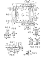
- the window 10 shown schematically in Fig. 1 consists of a dash frame indicated by dashed lines 12 and a sash frame 14 also indicated by dashed lines, which are connected to one another via a - generally designated 16 turn-tilt fitting such that, according to the rotational position of a handle 18th , The sash 14 can be rotated relative to the frame 12 about a vertical axis of rotation A (in FIG.
- the frame 14 can be tilted about a horizontal tilt axis B located on the horizontal, lower frame spar 12b relative to the frame 12 (position K of the handle and the drive rod latch); finally, the window 10 can be closed completely, by rotating the handle 18 in its closed position, which, like the corresponding closed positions of the drive rod latches, is denoted by Z (from “to”) in all the figures.
- the turn-tilt fitting 16 shown in simplified form, consists of an encircling connecting rod fitting 20, which is only interrupted in the area of the vertical wing frame spar 14a closer to the axis of rotation A, two opening scissors 22 and 24 in the area of the upper and lower, horizontal wing frame legs 14b and 14d, as well as a total of four striking plates on the frame side, of which the striker plate shown at the top left in FIG. 1 is designated by 26, the one below it at 28, the one shown at the top right in FIG. 1 (on the rotating axis side of the window 10) at 30 and the one below it at 32.
- the drive rod bolts interacting with these striker plates 34, 36, 38 and 40 in the corresponding order.
- the drive rod fitting 20 also has in its lower and upper, horizontal section each a drive rod lock 42 (upper lock in Fig. 1) and 44, each with an essentially U-shaped scissor lock element 46 and 48 on the side facing the drive rod lock a scissor arm 22a or 24a of the respective stay scissors 22 or 24 cooperate.
- the two opening scissors 22 and 24 can also have additional links which limit the tilt angle in a conventional manner (not shown).
- the wing frame end of each arm is slidably attached to the wing in the longitudinal direction of the respective wing spar. This is indicated in FIG.
- a lug 53 covering the respective drive rod section 50 or 52, to which the respective end of the scissor arm is attached in a longitudinally displaceable and pivotable manner about the indicated bearing pin 55.
- the end of the scissor arms on the frame side ends in a bearing piece 54, which is penetrated in each case by a bearing pin 56, which defines the already mentioned axis of rotation A and for this purpose is each held on a fork-shaped, upper or lower bearing 58 or 60.
- the two fork-shaped bearings 58 and 60 are mirror-symmetrical to one another about a horizontal one Center plane (intersection line 62 with the drawing plane of FIG. 1) formed and attached correspondingly symmetrically to the frame 12.
- the bearings 58 and 60 serve, depending on the position of the bearing pin 56 in them, either as a pure pivot bearing (upper bearing 58 in FIG. 1) or as a corner bearing with a turning and tilting function.
- the fork-shaped pivot bearing has a through-bore 6 0 c penetrating both fork halves 60a and 60b, the diameter of which is adapted to the diameter of the bearing bolt 56.
- the lower fork half 60b which is longer in the direction of the bearing bore 60c than the other fork half in FIGS. 4-6, has an inner bore extension 60d, namely towards the frame 12.
- the bearing pin 56 is driven into the through bore 60c to such an extent that it is supported at both ends of the fork halves 60a and 60b.
- the bearing pin 56 is shifted so far towards the longer fork half 60b (by appropriate driving in from above) that the upper end of the pin is exposed.
- the striking plates 26 to 32 already mentioned have the usual structure.
- the striking plate 28 serves as a tilting bearing, as shown in FIG. 1, in particular the additional view of the striking plate 28 (viewing direction of the vertical frame rebate circumferential surface of the frame).
- the drive rod latches 34, 38, 40 and 42 are out of engagement with the respectively associated striking plates or the scissor bar element.
- the drive rod latch 36 engages in the striking plate 28 which acts as a tilting bearing.
- the window can optionally be opened and closed again.
- Fig. 1 To be turned on the window, then the handle 18 in the clockwise direction of Fig. 1 is set to 0 90 to rotate (arrow C), whereafter a handle 18 supporting edges gear 62 the drive rod fitting 20 in motion.
- the small movement arrows drawn in Fig. 1 give the movement direction of the corresponding drive rod sections.
- Conventional corner drives 64 are provided in all four casement corners.
- the latches 24 to 40 correspondingly designated positions D are free of their associated striking plates 26 to 32.
- the latch 42 is now located within the scissor latch element 46, as a result of which the scissor arm 22a is fixed in the parallel position.
- the lower drive rod lock 44 is now in its position D and thus still within the scissor lock element 48.
- the sash frame 14 can be rotated about the axis A on the frame 12.
- the handle 18 is rotated further into its closed position (position Z)
- the bolts 34 to 40 penetrate into the respective locking plate 26 to 32, where they are fixed. Tapered surfaces on the striking plates, as well as on the scissor locking element 46, ensure that the sash is pressed on the frame in the direction perpendicular to the frame plane.
- Fig. 1 shows the window 10 with a right hinged.
- the two scissor bar elements 44 and 46 are exchanged, so that the conventional scissor bar element 46 is now attached to the scissor arm 24a and the scissor bar element 48, which is designed with extended U-legs, to the scissor arm 22a.
- the bearing 58 which is now located below, is converted into a corner bearing (driving in the bearing bolt 56 out of engagement with the shorter fork half 58d).
- the now overhead bearing 60 is converted from a corner bearing into a pure pivot bearing by displacing the bearing pin 56 to such an extent that it is supported on both fork halves at both ends.
- the striking plate 28 serving as a tilting bearing which would now lie at the top, must be removed and replaced, for example, by the striking plate 26.
- a striking plate 28 ' is to be fitted, which may be formed by the previous tilting bearing (striking plate 28), namely at low tilt angles.
- the order of the positions of the espagnolette locks has reversed (tilt ready position K now up instead of down), so that at larger tilt angles a noticeably larger angular range for the bolt movement occurs within the striking plate receptacle of the striking plate 28 when the wing is tilted.
- the tilt readiness position of the handle 18, again designated K is based on the window 10 unchanged, relative to the viewer, however, 0 180 rotated relative to the starting position in FIG. 1. It can be seen that the drive rod latches 36 to 40 are disengaged from the corresponding striking plates 26 30 and 32.
- the espagnolette bolt 34 engages in the striking plate 28 ', in which it can be moved back and forth in accordance with the tilt angle.
- the lower espagnolette bolt 48 is fixed in all of its positions Z, D and K within the scissor striking plate 48 provided with extended U-legs.
- the upper espagnolette bolt 44 can move past the conventionally designed striking plate 46 to tilt the window. In accordance with the tilting movement, the bearing pin 56 pivots in the bearing 58.
- the rotary handle 18 is again turned clockwise in FIG. 10 by 90 ° to position D, the individual drive rod sections moving in the direction of the small arrows shown.
- the bolt 44 moves into the striking plate 46, so that the opening arm 24a is fixed in the parallel position.
- the drive rod lock 34 is disengaged from the striking plate 28 ', so that the sash can now be rotated about the vertical axis A.
- the handle 18 is rotated into its position Z, whereupon the bolts 34 to 40 penetrate into the corresponding striking plates and are held there.
- a striking plate 28a is shown, which by screwing or unscrewing an additional part 28b (screws 28c) from one, only a pure locking function (position Z of the assigned part of the drive rod) can be converted into a tilting bearing or vice versa.
- the additional part 28b is provided with a receptacle 28e which is still open at the top in FIGS. 2 and 3 and is delimited on both sides by inclined surfaces 28d, the inclined surfaces 28d limiting the locking movement (double arrow E in FIG. 2) relative to the striking plate when the window is tilted .
- the striking plate is symmetrical to a vertical longitudinal center plane perpendicular to the frame rebate circumferential surface (mounting surface) and can therefore be used right-left. In order to take into account the different distance of the associated connecting rod bolt, which is in its ready-to-tilt position, from the tilt axis in the two types of stops, it is possible to replace the additional part 28b by a correspondingly modified additional part.
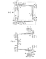
- FIGS. 7-9 shows a further type of locking of the respective lower stay scissors in a parallel position.
- Components which correspond in function to components in FIGS. 1 and 10 are provided with the same reference numerals, each increased by the number 100.
- the fixing takes place by means of a screw-in pin 170 screwed into the respective lower, horizontal sash frame spar 114b from the frame rebate circumferential surface. This penetrates both a pin opening 172 in the corresponding scissor arm 124a and an elongated hole 174 in the drive rod section 150 in order not to prevent its longitudinal movement when the drive rod fitting is actuated hinder.
- the end of the scissor arm 124a on the frame side ends in a bearing piece 154 which is mounted in a bearing 160 'which serves exclusively as a pivot bearing via a bearing pin 156 which defines the axis of rotation A.
- the wing lies on the scissor section between pin 170 and bearing 160 ' frame 114 with its underside in order to be able to derive weight forces into the bearing 160 '. It applies in a corresponding, but non-illustrated manner for the window 10 shown in FIG. 1 and 1 0th Due to the setting of the extension arm 124a by means of the pin 170 in the parallel position, the scissor arm 124 can be provided with a conventional scissor striking plate 146, as shown in FIGS. 7 and 8.
- the scissor arm 124a When the window is tilted, the scissor arm 124a is twisted accordingly.
- the pin opening 172 in the extension arm 124a is in the transverse direction, i.e. perpendicular to the casement plane, elongated, so that the scissor arm can rotate according to the coarsened representation in FIG. 9 with respect to the pin 172 and the drive rod section 150.
- the parallel position of the scissor arm 124a and drive rod section 150 according to FIG. 7 there is a small distance between the enlarged-diameter pin head 170a and the scissor arm 124a in order to enable the torsional movement according to FIG. 9.
- FIGS. 1 and 10 correspond to the same reference numbers, each increased by the number 200.
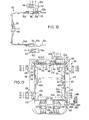
- a deflecting gear is integrated into the drive rod gear 262, which can be actuated by the handle 218, which is indicated by the opposite movement arrows in FIG. 11 is symbolized.
- the handle 218 is rotated, for example in the direction C from the tilting ready position into the rotating ready position, the drive rod section 252d adjoining the transmission 262 moves upward and the lower drive rod section moves downward 252c upwards (small arrows in FIG. 11).
- the tilt-ready positions K of the latches 234 and 236 are each on the side of the three positions K, D, Z, which is further away from the gear 262.
- the two lower latches 236 and 234 have the same, smallest possible distance from the corresponding tilt axis in both types of stops.
- One and the same locking plate 228 serving as a tilting bearing can consequently be used unchanged (after appropriate implementation) in both types of stops.
- Another advantage is that the order (for example, from right to left) of the drive rod lock positions of the drive rod lock 242 or 244 assigned to the upper scissor arm 222a or the lower scissor arm 224a is the same in each case. This opens up the possibility, according to FIGS. 2 and 3, of carrying out the conversion by screwing or unscrewing an additional part 248a. This additional part 2'48a, which can be seen at the bottom in FIG.
- FIG. 12 shows a further embodiment of a turn and tilt fitting 320.
- the drive rod gear 362 is in turn formed with an integrated deflection gear. Accordingly, the two conventionally designed scissor locking elements 346 on the upper and lower scissor arms 322a and 324a have the same shape and orientation.
- the short connecting rod section 350c which carries the respective associated connecting rod latches 344 and 342, can optionally be coupled to the connecting rod section 350d following in the direction of the connecting rod gear 362 via a rigid coupling 380, which is only shown symbolically. As shown in FIG. 12, the upper drive rod section 350c is coupled, but the lower drive rod section is uncoupled.
- the lower drive rod section 350c is in the position in which its drive rod lock 344 is currently in the closed position Z. Because of the decoupling, the drive rod lock 344 therefore maintains its position Z, regardless of the positions of the handle 318, in which it fixes the scissor arm 324a in a parallel position. If the frictional engagement between the drive rod lock 344 and the scissor lock plate 346 is not high enough to always ensure that the drive rod lock 344 does not move out of its position Z, the drive rod section 350c can be fixed to the sash frame in a manner not shown .
- the window 410 consists of a frame 412, which is only indicated by dashed lines, and a casement 414 which is held on the frame 412 by means of a turn-tilt fitting, generally designated 416.
- the fitting 416 consists of an encircling drive rod fitting 420, which is only interrupted on the lower, horizontal casement frame 414b by a short piece, an opening scissor 422, a pivot bearing 458 holding the opening end of the scissor stay, a corner bearing 460 and a total of five striking plates 426, 428, 430, 431, 433, the latter two being attached to the lower, horizontal frame spar 412b as additional striking plates compared to the previously described exemplary embodiments.
- the drive rod fitting 420 consists of a series of interconnected drive rod sections 452, a total of four corner deflections 464, a reversing gear 465 in the region of the center length of the upper, horizontal sash frame spar 414d and two edge gears 462a and 462b on, in FIG. 13, left and right vertical sash frame spars 414c and 414a.
- a single handle 418 can optionally be plugged onto one or the other edge gear 462a and 462b. 13 shows a polygonal insertion opening 463 for this purpose on the unused gear 462b.
- FIG. 13 shows a bearing block 453 on both sides of the deflecting gear 465, which extends over the respective drive rod section and to which, depending on the type of stop, the extension arm 422a is attached.
- An essentially U-shaped scissor striking plate 446 is attached to the scissor arm 422a in a conventional manner and interacts with a corresponding drive rod lock 442 in the manner shown. It can be seen that in the tilt-ready position of the handle 418 denoted by K, the connecting rod latch 442 assumes a position also denoted by K, in which it disengages from the U-shape of the scissor latch element 446. On the other hand, if the handle 418 is turned in the direction of arrow C (clockwise in FIG. 13), the drive rod sections 452 experience a displacement indicated by the small solid arrows.
- the locking positions corresponding to the ready-to-turn position of the handle 418 are shown in FIG 13 also denoted by D; the locking position of the handle 418, which is denoted by Z, is also associated with locking positions which are denoted by Z.
- the locking positions indicated in brackets relate to the window 410 converted to the left stop with the handle 418 inserted into the right edge gear 462b and rotatable between the positions K, D and Z also indicated in brackets.
- the two upper side striking plates 426 and 430 only interact in the closed position Z with the associated drive rod locks 434 and 438, respectively.
- the striking plate 428 which is located at the bottom left in FIG. 13, also has the function of a tilting bearing.
- the two lower striking plates 431 and 433 are similar to the striking plate 428.
- the drive rod locks 435 and 437 assigned to the locking plates 431 and 433 are located within a relatively wide recess 431a and 433a of the two identically designed locking plates 431 and 433, which are attached in the opposite orientation to the frame frame 412b .
- the bolts 435 and 437 In the ready-for-rotation position, the bolts 435 and 437 are out of engagement with their striking plates; in the closed position Z, the bolts 435 and 437 are held in the corresponding striking plate.
- the aforementioned tilting bearing 460 can be formed, for example, by attaching, in particular screwing on, a sash-side corner bearing part 460a to the corresponding lower sash frame, which is provided with a vertically downwardly projecting bearing pin 460b, which extends from an upwardly open receiving opening 460c of a corner frame part 460d on the frame side is recorded.
- the bearing opening 460c is widened toward the fastening surface, that is to say toward the frame, so that the pin 460b used has the required size. Can perform tilting movement.
- the striking plates 426, 430, 446a free the associated drive rod bolts, whereas the striking plates 428, 431 and 433 grip the corresponding drive rod bolts with play.
- the window can therefore be opened. If the handle 418 is turned to the ready-to-turn position (with the window tilted), the drive rod lock 442 penetrating into the striking plate 446 fixes the opening arm 422a in a parallel position, whereas all other locking elements are released.
- the window can therefore be rotated about the axis of rotation A defined by the upper bearing 458 and the corner bearing 460.
- the bearing 458 is to be detached from the frame;
- the stay scissors 422, which may still be connected to the pivot bearing 458, can be detached from the casement (here from the right bearing bracket 453).
- the pivot bearing 458 is now to be attached in the appropriate position in the area of the upper left corner of the frame; the stay scissors 422 is on the casement (here on the left bearing block 453). to connect.
- the corner bearing 460 is to be moved to the left frame corner.
- the striking plate 428 is also from the left to the right frame side to be laid, keeping the orientation in the vertical direction.
- the installed striking plate 428 (indicated by dashed lines in FIG. 13) interacts with a drive rod bolt 436a, which has not yet been mentioned and which is at the same height as the drive rod bolt 436, which previously cooperated with the striking plate 428.
- the three possible positions of the handle 418 on the right edge gear 462b are again identified by the letters K, D and Z. It can be seen that the handle 418 points upwards in the K position for both types of stop and points downwards in the Z position. In position D the handle 418 points with its free end to the opposite, unused gear.
- the locking positions K, D, Z corresponding to the handle positions K, D and Z of the handle attached to the right gear 426b are given in brackets.
- the direction of movement of the corresponding drive rod sections when the handle 418 is moved in the direction of the likewise dashed arrow C ' is indicated by small dashed arrows.
- the bolt positions correspond to one another in the case of both types of stop, so that no changes need to be made to the striking plates, except for the conversions described above.
- the upper connecting rod bolt 434 interacts in a corresponding manner with the bolt striking plate 446 of the scissor arm 422a articulated on the left.
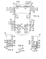
- the rotary tilting fitting shown in FIG. 14 differs from that in FIG. 13 primarily in that the deflection gear 465 is omitted to simplify the construction.
- Components in FIG. 14 to which components in FIG. 13 correspond are provided with the same reference numbers, in each case increased by the number 100. 14, the locking positions corresponding to the positions K, D and Z of the handle 518 inserted into the left gear 562a are designated with K, D and Z, and the locking positions corresponding to the positions of the handle inserted into the right gear 562b with (K ), (D) and (Z).
- a base body 582 which is the same in both bearings and which is provided, for example, with two screw openings 584 for fastening to the frame.
- the base body 582 is formed with a step 586 projecting in the direction perpendicular to the frame plane, the upper edge of which is rounded and merges into a substantially horizontal step surface 588.
- This step surface 588 serves as a run-up surface for a pin 590, which is attached to the corresponding frame and projects vertically downward, provided that the base body 582 is to serve as a run-up bearing 580.
- the run-up surface 588 serves as a standing surface for the corresponding pin 590 (on the other corner of the frame).
- a substantially vertical holding plate 592 is screwed to the substantially vertical end face 594 of the steps 586, in the example shown by means of a countersunk screw 598 screwed into a horizontal screw thread 596 of the step 586
- lateral cheeks 599 indicated in FIG. 15, follow on both sides of the pin 590.
- the step surface 588 merges into an expansion 588a, into which the lower end of the pin can penetrate when the window is tilted.
- the holding plate 592 is chamfered on its inside facing the base body 582 in the region of the upper edge (inclined surface 592a).
- a cover plate 590a can be attached to the pin 590, which corresponds approximately in shape and arrangement to the holding plate 592.
- the holding plate 590a is formed on its inside assigned to the base body 582 with a ring 590b, into whose ring opening 590c the pin 590 can be inserted. When the window is closed, the ring 590b can penetrate the widening 588a.
- FIGS. 18 and 19 a further embodiment, designated 616, of a right-left convertible turn-tilt fitting is shown in simplified form, with the omission of the lower half of the fitting, which is to be supplemented, for example, in accordance with FIG. 14.
- Components in FIGS. 18 and 19 that correspond to those in FIG. 14 are included. the same reference numerals, each increased by the number 100.
- the only difference from the embodiment according to FIG. 14 is that now a complete structural unit 602 is removed from the upper connecting rod fitting section (connecting rod including the faceplate, not shown) and the stay scissors 622 attached to the faceplate (symbolized by a lug 654) when changing the stop and , rotated by 180 ° around a vertical axis, is reassembled.
- the pivot bearing 658 can be used together with assembly 602 or separately.
- the connection of the upper connecting rod section 6 5 2, as part of the unit 602, at both ends to the next following connecting rod section is only symbolically indicated in FIGS. 18 and 19 by a connecting bolt 604.
- the drive rod sections can be connected to one another in the usual way, for example by a snap connection.
- the Scherenrie can be left unchanged 646g elelement.
- the two upper striking plates 626 and 630 indicated in FIGS. 18 and 19, on the other hand, have to be converted (according to FIG. 14) by rotation by 180.
- Fig. 20 shows such an attached to the upper left frame corner A scissor stay bearing 700, which is fastened to the frame 704 by means of a total of four Phillips screws 702.
- the opening scissors of the window which is hinged here on the right, is also articulated on the opposite right, not shown, frame frame corner.
- an end piece 708 can be inserted into the bearing part of the stay scissor stay 700 designed as a bearing fork 706, which end piece corresponds to the end piece 54 in FIGS. 1 and 4 to 6 and which is to be attached to the corresponding end of the swing arm when left-hinged.
- the stay scissor stay 700 that is not required can also be covered by a hood 710 shown in section in FIG. 21 made of a stamped sheet metal part or a plastic part.
- the hood 710 is provided with parallel clamping jaws 712 projecting downward in FIG. 21, which clamp the vertical frame spar 714 between them and in this way detachably fix the hood 710 to the frame.
- the hood 710 When changing the stop type, the hood 710 must be placed on the right-hand scissor stay bearing that is not required.
- FIG. 22 shows a modification of the embodiment according to FIGS. 18 and 19.
- the structural unit comprising the stay scissors which can normally be attached in two different positions to the upper casement frame 716 and is generally designated 718, now only comprises the stay arm 71 9 , an additional arm 720 and a faceplate section 722 (ie no drive rod section as in FIGS. 18 and 19).
- a continuous drive rod 724 is provided on the upper casement frame 716 (which is not necessarily the case since this could be replaced by a continuous drive rod on the lower sash frame spar), this drive rod 724 can be covered by a drive rod cover 726 indicated in FIG. 22.
- the unit 718 can be securely and quickly attached to the cover 726 in one of the two orientations via a so-called buttonhole connection.
- FIG. 22 shows the structural unit 718 in an orientation corresponding to the right-hand stop just above the upper frame spar 716 shortly before assembly on the frame.
- a total of three elongated holes 728 are formed on the faceplate section 722, which correspond to three retaining pins 730 on the top of the cover 726.
- Insert sections 728a each provided on the right end of the elongated holes 728 have a circular outline which corresponds to the diameter of the enlarged head 730a of the pins 730.
- the width of the remaining elongated longitudinal section 728b corresponds to the pin shaft diameter.
- the faceplate section 722 To fasten the faceplate section 722 to the frame, it is placed on the frame in such a way that the pins 730 simultaneously penetrate the insertion sections 728a until the pin heads 730a finally protrude above the faceplate section 722. Subsequently, the faceplate section 722 is shifted to the right in FIG. 22, so that the pins 730 penetrate with their shank into the narrowed elongated hole section 728b. In this position, the faceplate section 722 is fixed to the casement frame by screwing a fixing screw 732 with the knurled head 732a above the faceplate section E 722 into a screw hole 734 of the cover 726:
- the two outer pins 730 are symmetrical to the inner pin 730, the latter in turn on the length middle of the upper casement 716. Because of this symmetry, the same pins 730 can also be used to fasten the assembly 718 in the left-hinged orientation. For this purpose, only the assembly 718 has to be rotated by 180 ° about an axis of rotation perpendicular to the plane of the faceplate section and again placed on the three pins 730. The extension arm 719 is swiveled to the other side. After pushing into the final assembly position (to the left in FIG. 22), the fixing screw 732 is then screwed into a further screw hole 736. The two screw holes 734 and 736 are again symmetrical to the center frame length.
- two additional arms 738a and 738b are permanently attached to the faceplate 739 on the upper horizontal wing frame spar 742, one of the two then depending on the type of stop Additional arms must be coupled to the 744 arm.
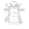
- the extension arm 744 is mounted in the usual manner (not shown) on the faceplate (via an elongated hole), the bearing point being able to be different with right-hand and left-hand hinging or, similarly, with central storage; Lich Fig. 41, can also be the same for both types of attack.
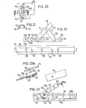
- the manner in which the additional arm 738 required in each case is coupled to the extension arm 744 can be seen from FIGS. 23 and 23A.
- a bolt 746 projecting downward is riveted to the extension arm 744 with a bolt head 746a enlarged in diameter.
- a rubber washer 740 is held on the auxiliary arm 738 by means of a mounting plate 745 riveted to the underside of the auxiliary arm 738 (rivets 743). Corresponding openings in the mounting plate 744 and in the auxiliary arm 738a are aligned with the opening of the rubber washer 740. The inner diameter of the rubber washer 740 corresponds approximately to the bolt diameter.
- the bolt 746 with its bolt head 746a must therefore be pushed ahead through the rubber disk 740 held on the additional arm 738 until the enlarged-diameter head 746a reaches the other side of the rubber disk 740. Since the rubber disc 740 then lies against the bolt circumference, possibly with play, there is a low-friction pivot bearing between the two parts, which holds together reliably, since when the window is assembled, essentially no forces occur in the direction of the axis of the bolt 746 between the opening arm 744 and additional arm 738 act. If the type of stop has to be changed, the connection between additional arm 738 and extension arm 744 can be easily released by pulling the two parts apart.
- latching connection between the additional arms 738 and the faceplate 739 provided.
- This consists of a latching projection on the underside of the respective additional arm 738 and an associated latching recess 748 in the faceplate 739 underneath.
- the latching projection is formed, for example, by a plastic plug 750 which is fastened to the additional arm 738 in the manner of a rivet.
- the locking recess 748 is in the example shown in Fig.
- the respective drive rod system can assume a total of three drive element positions, to which the three different positions of the drive rod latches that correspond, each with the same spacing, correspond.
- the individual drive element positions are assigned to the functional fitting positions of one and the other type of stop.
- the two fitting functional positions assigned to a driving element position are either the same for both types of stops (FIGS. 1-13) or different from one another (FIGS. 14-19).
- the fitting functional positions for the right-hand stop are marked with the letters Z (for the closed position), D (for the ready-to-turn position) and K (for the ready-to-tilt position); the corresponding fitting functional positions at the left stop are bracketed in the figures.
- the total stroke of the espagnolette bolts therefore coincides with the bolt stroke required for one type of stop and with the bolt stroke required for the other type of stop.
- the overall stroke length required is doubled compared to the stroke path required only for one type of stop.
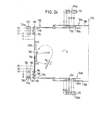
- the latches 764 shown can move between the positions Z, D and K; in position Z the handle 766 points downwards, in position D it lies horizontally and in position K it points upwards.
- the upper scissor striking plate 766a has the same shape, the same orientation and the same attachment location on the respective opening scissor arm 768 as the lower scissor striking plate 766b.
- the striking plate shape corresponds to a U, which opens in the direction away from the window axis of rotation 770.
- the leg length is dimensioned such that the associated drive rod lock 764 engages in all possible positions, except for the position furthest away from the axis of rotation 770 (position K in the upper striking plate 766a or position (K) in the lower striking plate 766b).
- the bolt In the innermost position (position K up or position (K) down), the bolt is gripped with movement due to an extension 772 of the U-shape, in contrast to the other bolt positions, in which the bolt between parallel inner sides of the U-shape in is essentially determined without play (same locking level).
- a locking striking plate 774a or 774b is provided on the corners, which have the same shape and are attached to the frame in an orientation and position symmetrical to the center of length of the vertical bar.
- Each locking striking plate 774 has, at its end facing away from the respective other striking plate, a slightly curved ramp surface 776 for a ramp protrusion 778 on the respective sash corner.
- This projection 778 is shown in simplified form in FIG. 24 as a horizontally extending nose on the respective corner deflection 779.
- Adjoining the run-up surface 776 is a tilting section of the striking plate, which consists of two side jaws 780 with mutually facing cheek surfaces that move away from one another towards the other striking plate. Adjoining this is a rotary section which is free from projections which hinder the movement of the corresponding bolt.
- a closing section of the locking striking plate 774 which is formed from two lateral jaws 782, which define a channel between them, the channel width of which corresponds to the bolt diameter and which on both sides (towards and in the direction of away from the other locking striking plate) is open.
- the associated bolt 764 has moved in the direction of the axis of rotation up to position D, in which the bolt continues to be gripped by the U-shape of the scissor striking plate without play.
- the bolt assigned to the upper locking striking plate 774a on the left in FIG. 24 has moved downward into its position D outside the striking plate 774a and is thus free of the striking plate.
- the locking element 764 of the lower locking striking plate 774b has accordingly moved into the rotary section of the striking plate (position D). The window can therefore be opened and closed again.
- the latches move into the positions indicated by K.
- the bolt assigned to the upper scissor striking plate 766a is now outside the U-shape, so that the upper opening scissors 762a can pivot.
- the bolt associated with the left upper locking striking plate 774a is still free of this striking plate in its position K, so that it does not hinder the tilting of the window.
- the bolt assigned to the lower striking plate 774b is located between the jaws 780 of the tilting section, as in a conventional turn-tilt fitting.
- the jaws 780 hold the lower casement corner on the frame.
- the bolt 764 assigned to the lower scissor striking plate, 766 is in its position K in the extension 772 of the U-shape.
- the stay arm 768 on the stay frame-mounted stay scissor stay is twisted slightly; due to the extension 772 and the resulting movement of the bolt within the U-shape, the scissor locking plate 766b attached to the opening arm 768 can rotate relative to the bolt 764 (about an axis of rotation parallel to the longitudinal direction of the opening arm), so that the opening arm also on the can twist away from the axis of rotation 770 side of the bolt 764.
- this primarily reduces the material stress in this area.
- the handle position (Z) at the left stop corresponds to the same locking positions as in the closed position at the right stop, since only the handle 766 was changed when the stop was changed. With both types of stops, the handle points downwards in the closed position.
- the window provided in the preassembled state and adapted only by the end user to the respectively desired of fitting the window can be fully assembled until the handle 766 delivered to the end user, which then only the separately g e-handed handle in a corresponding orientation to the edges of transmission has to attach.
- the edge gear 783 indicated in FIG. 24 is designed such that it has a total drive element stroke (Distance between the driving element positions K and ( K )), which is twice as large as the stroke required in conventional windows with only a single attachment option (distance between the locking positions K and Z or the locking positions ( K ) and (Z Such an increase in stroke can generally be achieved without difficulty, for example by a correspondingly large payment length of a toothed rack as part of the edge gear.
- a symbolically illustrated edge gear 783 ' is used, which only has a simple stroke corresponding to the distance Z-K.
- a pinion 782a which is connected in a rotationally fixed manner to the corresponding handle 766 'is indicated and which engages in a correspondingly toothed section 782b of a rack section within the edge gear 783'. Stroke position extends the toothed Abs cut 782b up from pinion 782a; the tooth length corresponds to the stroke in one type of stop. So if you turn the handle 766 'from the closed position Z to the ready-to-turn position D or the turn-tilt ready position K, the two latches 764' shown move accordingly into the specified positions D or K. The rest of the turn-tilt fitting 760 ' is to be completed in accordance with the turn-tilt fitting 760 in Fig. 24.
- a so-called screw-on gears 790 according to FIG. 27 are used.
- the handle 792 is generally not detachable from the actual gearbox and again, in another orientation, can be plugged on, so that a specific position of the drive element engaging the drive rod 794, here coupling sword 796, corresponds in each case to a specific rotational position of the handle 792.
- a screw-on gear unit 790 with only a simple stroke, corresponding to the stroke required for a type of stop is used, the stroke enlargement required in the embodiments according to FIG.
- the 24 is obtained by coupling the coupling sword 796 optionally to one of two spaced-apart coupling bolts 798.
- the upper coupling pin 798a in FIG. 27 is coupled to the coupling sword 796, for example, when it stops to the right. 27 shows both the possible positions of a bolt 799 in the manner customary here and the positions of the coupling sword 796.
- the starting position is again the closed position Z at the right-hand stop. If the handle 792 is now turned to the ready-to-turn position or the ready-to-tilt position, the coupling sword 796 moves and with it the bolt 799 down into the positions D or K. When the type of stop is changed, the handle 792 is again in the Starting position Z rotated.
- Such a long slot is particularly unfavorable because, in the area of this long slot, the faceplate together with the drive rod cannot be attached to the sash frame by fastening screws.
- the solution according to FIGS. 28 and 29 avoids such a long faceplate elongated hole, namely in that a single coupling pin 80d is used, which can be screwed into one of two screw-in holes 802 of the drive rod 804 according to the selected type of stop.
- the two screw-in holes 802 are spaced apart from one another in the longitudinal direction of the connecting rod, corresponding to the simple stroke (distance ZK).
- the faceplate 806 covering the drive rod 804 has an elongated hole 808 with a length corresponding to the simple stroke.
- the coupling sword 814 ' acts directly on the drive rod 804', specifically via an appropriately angled coupling sword end 814a, which can be inserted into a corresponding slot recess 804a 'of the drive rod 804'.
- two slot recesses 804a 'spaced apart from each other in accordance with the simple stroke are provided, so that the stop conversion of the screw-on gear 810' takes place in the same way as with the screw-on gear 810 according to FIGS. 28 and 29.
- a separate part is saved 800, which still has to be converted.
- a handle gear in particular edge gear with half -Olive as shown in FIGS. 24 and a sufficiently large stroke
- the handle 766 in FIG. 24 could also be turned into a horizontal rotational position with the handle end pointing to the left.
- this can lead to confusion of the operator and, on the other hand, depending on the design of the turn-tilt fitting, it can lead to incorrect operation.
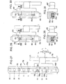
- a stroke limit stop is provided according to FIG. 32.
- This consists of a bolt 824 screwed into the faceplate 822 covering the drive rod 820, which engages with its bolt end 824b, which is remote from the bolt slot head 824a, into an elongated hole 826 of the drive rod 820.
- a bolt 828 screwed into the drive rod 820 is also shown in FIG. 32, which can be moved from the position Z down to the positions D and K in the right-hinged version of the turn-tilt fitting not shown.
- the length a of the elongated hole 826 corresponds to the simple stroke, that is to say the distance b between positions Z and K of the latch 828, taking into account the diameter of the bolt end 824b. Since the bolt 824 in FIG. 32 is located at the lower end of the elongated hole 826, the bolt 828 can consequently be moved freely between its positions Z and K, but not in the direction of the positions (D) and (K) to be reached when the type of stop is changed. .
- the screw bolt 824 is unscrewed from its screw-in hole 830a and screwed into an overlying screw-in hole 830b of the faceplate 822, the distance between the two screw-in holes 830a and 830b being so dimensioned is that the bolt end 824b is now at the top of the slot 826.
- the drive rod and bolt 828 can therefore only move upwards from this position, namely by the simple stroke. It is advantageous that the length of the longitudinal slot 826 in the drive rod corresponds only to the simple stroke, so that there is only a slight mechanical weakening of the drive rod 820.
- the longitudinal slot 826 not in the drive rod but in the faceplate and accordingly screw a bolt in the drive rod in two different positions, which is disadvantageous when it comes to the most uniform, appealing exterior of the fitting.
- a stop element in the form of a tab 840 directly engages the bolt 842.
- the bolt 842 is screwed into the drive rod 844 and passes through a correspondingly long slot 846 in the faceplate 848 covering the drive rod 844.
- the bolt 842 bears on the outside of the faceplate 848 with an enlarged bolt head 842a.
- the tab 840 is fastened to the faceplate 884 at the upper end of the slot 846 in FIG.
- the tab 840 is accordingly to be screwed onto the lower end of the longitudinal slot 846 in FIG. 33 with the free tab end directed upward.
- a corresponding screw-in opening 852b is formed in the face plate 848 at the lower La nglochendes.
- a tab 862 is pivotably mounted on the faceplate 860 about a fastening bolt 864 (rivet) about an axis 866 perpendicular to the faceplate plane.
- the pin 864 is located in the area of a tab end; in the area of the other end of the link, the link 862 is rigidly connected to a stop bolt 868.
- the length of the longitudinal slot c corresponds to the length a of the longitudinal slot 826 in FIG. 32, taking into account the diameter of the projections 824b and 870.
- the drive rod 876 can consequently move downwards, corresponding to the simple stroke .
- the flexible tab 862 is bent away from the faceplate 860, which is facilitated by a bolt head 878 of the bolt 868 on the side of the tab 862 facing away from the faceplate 860, since this can be easily gripped by hand. Then the. Tab 862 pivoted about axis 866 by 180 °.
- the head 878 is released, whereupon the tab 862 again assumes its elongated shape and the projection 870 both into a direct opening 880 which is adapted to the projection circumference the faceplate 860 also penetrates into the longitudinal slot 874, specifically at its upper end in FIG. 34.
- the drive rod 876 can consequently only be moved upwards, in accordance with the simple stroke, from this starting position.
- FIG 35 shows a modified embodiment in which the tab 862 'is fastened to the window sash by means of a wood screw 864'.
- the wood screw 864 ' passes through both a screw opening 882 of the faceplate 860' and the slot 874 '.
- the protrusion 870 ' is formed by a bolt riveted to the tab 862'.
- the tab 862 ' is rigid in itself.
- the wood screw 864 ' is unscrewed at least so far that the projection 870' can be completely pulled out of the passage opening 872 'of the faceplate 860'.
- the tab 862 ' is then fastened in a position rotated by 180 ° with respect to the screw axis 866' on the faceplate 860 'by screwing in the wood screw 864', the projection 870 'again passing through the upper passage opening 872' and into the longitudinal slot 874 ' the upper end engages.
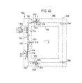
- Fig. 36 is a turn-tilt fitting, similar to that shown in Fig. 24; Components in FIG. 36 which correspond to those in FIGS. -24 are provided with the same reference numbers, each increased by the number 200.
- the turn-tilt fitting 960 is in turn designed for a right-hand stop (pivot axis 970) and can be converted quickly and easily to the left-hand stop in the manner to be described.
- the total stroke that can be carried out by the bolts 964 (both types of stop combined) is, as in FIG. 24, twice the simple hubs one of the two types of attack.
- M an receives a total of five possible locking positions.
- the middle bolt position is assigned to the closed position Z when it is hinged to the right and at the same time to the closed position (Z) when it is hinged to the left.
- the two outermost bolt positions are in turn assigned to the readiness to tilt in each case one of the two types of stop.
- a comparison of the functional positions of the bolt 764 or 964 assigned to the upper scissor striking plate 766a or 966a in FIGS. 24 and 36 shows that the order of the functional positions is reversed.
- the handle 966 is also directed vertically upward in its closed position Z.
- the handle 966 points in the horizontal direction (towards the axis of rotation 970); in its readiness for tilting, the handle 966 points downward.
- Due to this position reverse the upper scissor lock plate 966a and the lower scissor striking plate is 966b 180 0 rotated compared to Fig. 24 attached to the flaring scissor arm 968, that is, with the U-shaped opening to the rotation axis 970 toward.
- the shape of the striking plates 966 is the same as that of the striking plates 766.
- locking striking plates attached to the vertical frame member can also be attached but rotated through 180 ° and shifted towards the edge gear 983.
- the two locking striking plates 974a and 974b have the same shape and are attached at the same distance and the same orientation from the axis of rotation 970 to the upper and lower frame members. They in turn consist of three sections, a closing section, a rotating section and a tilting section.
- the closing section in turn consists of two opposing jaws 982, which hold the latch 964 between them essentially without play and which form a correspondingly narrow channel which is open to both sides in the direction of movement of the latch element 964.
- the rotary section 984 is milled out in such a way that the bolt 964 which is in the ready-for-rotation position D can pivot freely past the striking plate 974.
- the tilting section consists of an enlarged recess which is open in the direction of the closing section and into which the latch 964 engages in its tilt-ready position K with a slight play in the direction perpendicular to the frame level.
- the lower locking elements 964 move into the ready-to-rotate position D or the tilting advisory position K away from the axis of rotation 97o to the left, that is to the left end in each case two striking plates 974 b and 966b.
- the upper locking elements 964 increasingly move away from the striking plates 974a and 966a.
- the locking striking plate 974a already releases the associated bolt 964, whereas the scissor striking plate 966a releases the corresponding bolt 964 continues to grip without play, so that the upper stay scissor arm 968 is still fixed in parallel position on the upper horizontal sash bar.
- the lower locking striking plate 964d allows the locking element to be moved past the pivot section 984; the under scissor striking plate 966b engages around the associated bolt without play, so that the lower scissor arm 968 is also fixed in the parallel position.
- the window can thus be opened and closed again without hindrance.
- the two lower bolts 964 are each in the extensions of the two striking plates 974b and 966b, which define the horizontal tilting axis below and allow the tilting movement due to the play.
- the upper bolts 964 are both outside the two striking plates 974a and 966a, so that, under the control of the upper scissor arm 968, the window can be tilted open and closed again.
- the handle 966 in the dotted position on the edge gear 983 may need to be attached, as indicated by the small arrows in FIG. 36 previous removal from the bevel gear 983 and rotation through 180 ° around the handle axis. Then or beforehand, the window is rotated a total of 180 ° about an axis perpendicular to the window plane.
- FIG. 37 shows a further variant of a turn-tilt fitting with doubling of the stroke.
- Components in Fig. 37 that correspond to components in Fig. 24 are given the same reference numerals, respectively increasingly provided with the number 300.
- the turn-tilt fitting 1060 which is again shown in the right-hand stop (axis of rotation 1070), differs from the embodiments according to FIG. 24 and according to FIG. 36 essentially in that the middle locking position of the five possible locking positions, both the ready-to-turn position D at the right-hand stop and that Ready-to-turn position (D) corresponds to left-hinged. This position is followed on the one hand by the tilt ready position and the closed position of one type of stop and on the other hand by the tilt ready position and the closed position of the other type of stop.
- each scissor striking plate is divided into the following sections, starting from the end of the striking plate closer to the pivot bearing:
- Closing section f in the form of a bolt 1064 which is open in the direction away from the axis of rotation 1070 and which is in the closed position Z, essentially without a recess encompassing play;
- Tilting section g which allows the bolt in the corresponding position (K) for the upper striking plate or (K) (for the lower striking plate) to emerge from the side;
- Closing section h of two opposing jaws which form a channel in FIG.
- a tilting section i which in turn is formed by two opposing webs, which engage around the bolt located in the corresponding tilt-ready position (position (K)) at the upper scissor locking plate with play; Closing section k at the striking plate end, which is further away from the axis of rotation 1070; Similar to the closing section f, in the form of a recess which engages around the bolt without play and is open towards the axis of rotation 1070.
- Both scissor striking plates 1066a and 1066b have the same shape and are attached to the respective opening scissor arm 1068 in the same orientation and position.
- the upper and lower locking striking plate 1074a or 1074b corresponds in shape to the above-described scissor striking plate 1066 with the one difference that the middle striking plate section h 'assigned to the common ready-to-turn position is milled off in such a way that the associated bolt 1064 is milled can move past the striking plate 1074.
- one or more (in the illustrated example 2) locking locking plates 1075 may be provided on the pivot bearing distant vertical frame spar.
- the end sections f "of the striker plate 1075a corresponding to the two outermost bolt positions (position Z and position (Z)) correspond in shape to the end section f of the scissor bolt striker plate 1066, the recesses of the two sections f" each in Direction to the opposite section are open.
- the assigned bolt 1064 is therefore only gripped by the respective striking plate '' 1075 in the two closed positions Z and (Z).
- the starting position of the handle 1066 is the rotary ready position D, in which the handle protrudes upward from the edge gear 1083.
- the two scissor striking plates 1066a and 1066b each fix the opening scissor arm 1068 in the parallel position on the frame spar, whereas the striking plates 1074a and 1074b, 1075a and 1075b release the respective latch 1046 so that the window can be opened and closed again without further ado. If the handle is now rotated clockwise in FIG. 37 by 90 ° into the ready-to-tilt position K, the upper right bolt enters section g of the upper scissor striking plate which is open on both sides, so that the opening scissor arm is released.
- the lower right bolt 1064 moves into section i , so that the scissor arm 1068 is still attached to the lower horizontal casement, albeit with play to facilitate the torsional movement when tilting.
- the upper left bolt 1046 enters section g of the locking striker 1074a so that it is released from the striker.
- the lower left bolt 1046 is defined in section i of the lower locking striking plate 1024b with tilt play.
- the two locking striking plates 1075a and 1075b attached to the left vertical frame frame still do not hinder the movement of the respective latch 1064. The window can therefore be tilted open and closed again.
- the handle 1066 With a left stop, the handle 1066 is attached to the edge gear 1083 in the dotted orientation of the handle, the locking elements 1064 taking up their central position. If the window is to be converted from left-hinged to right-hinged, the handle 1066 must be removed from the edge gear 1083 in its ready-for-rotation position D and finally afterwards, as indicated by the small arrows Rotation of 180 0 reattached to the edge transmission 1,082th This new position corresponds to the ready-to-turn position (D).
- F ig. 38 shows a further embodiment of a turn-tilt fitting in which the overall required stroke of the bolt is increased by 50% compared to the stroke required for a single type of stop.
- Components in FIG. 38 which correspond to the functions in FIG. 37 are provided with the same reference numerals, each increased by the number 100.
- the turn-tilt fitting 1160 has a total of four possible drive element positions.
- the two outer drive element positions correspond to the tilt-ready position K of one type of stop or the tilt-ready position (K) of the other type of stop.
- the two inner latch positions are each assigned two functional positions, namely a functional position of one type of stop and a functional position of the other type of stop.
- the bolt 1164 assigned to the upper scissor striking plate 1166a it can assume the following functional positions from left to right (in the direction of the axis of rotation 1170):
- the bolt position to the left corresponds to the ready-to-tilt position K at the right-hand stop ;
- the next following bolt position corresponds to both the ready-to-turn position D for a right-hand stop and the closed position (Z) for a left-hand stop;
- the functional positions Z, (D) are assigned to the next latch position.
- the last bolt position is assigned to position (K). In position K, the bolt 1164 is located outside the upper scissor striking plate 1166a.
- the bolt In the next position (D) or (Z), the bolt is located between the legs in the direction away from the axis of rotation 1170 open U-shape of the scissor striking plate 1166a. Both in this position D , that is to say in the next position Z, the U-shape legs engage around the latch essentially without play. Finally, in position (K), the bolt is in a widening 1172 of the U-shape.
- the lower scissor striking plate 1166b has the same shape as the upper striking plate and is attached to the lower extension arm 1068 in the same orientation and at the same distance from the axis of rotation 1170.
- Locking striking plates 1174a and 1174b are attached to the upper and lower horizontal frame rails, which cooperate with corresponding bolts 1164.
- the upper locking striking plate 1174 consists only of a closing section consisting of two mutually opposite channels 1175a which form a channel which is open to the left and right. In position Z (ie the closed position at the right-hand stop), the striking plate 1174a engages the bolt 1164.
- the lower locking striking plate 1174b has, in addition to a correspondingly configured locking section 1175b for the bolt 1164 in the Z position, a rotating section 1177b and one subsequent tilting section 1179b.
- the bolt in position D can freely pass the rotating section 1177b thanks to the corresponding milling of the striking plate in this area.
- the latch located in the position K engages in an enlarged recess of the tilting section 1179b which is open towards the closing section 1172b, thereby defining the tilting axis.
- the window can consequently be turned 90 ° counterclockwise after the handle 1166 pointing downward in the closed position Z Standby position D to be opened, as the V ER- riege lungs striking plates 1174a and 1174b release the corresponding latch and each of the two extension arms 1168 fixed to the respective horizontal frame spar wing in parallel position.
- the upper opening scissor striking plate 1166a releases the corresponding bolt so that the window can be tilted open.
- the handle 1166 is to be mounted on the edge gear 1183 in the ' dotted orientation (handle pointing in the horizontal direction to the axis of rotation 1170).
- the two locking strikers 1174a and 1174b must be interchanged, which is shown in FIG . 38 is indicated by bracketing the two interchanged striking plates.
- the upper and lower latches are not mounted exactly one above the other on the associated drive rod, but are offset in the horizontal direction by the adjustment distance x, that is to say by the distance between adjacent functional positions.
- the upper short locking striking plate 1174a can be attached at a right-hand stop at a location on the upper frame spar which is at exactly the same distance from the axis of rotation 1170 as the fastening point of this short striking plate after changing the type of stop on the opposite horizontal frame spar.
- the bolts assigned to the scissor striking plates 1166a and 1166b are also horizontally offset by the amount x from each other, so that the two (not to be exchanged) scissor striking plates have the same distance from the axis of rotation 1170. This facilitates the production of the fastening holes for the locking plates in the frame.
- the handle 1166 in position Z is pulled off, rotated 90 ° counterclockwise and reattached to the bevel gear 1183. Then or beforehand, the entire window is rotated by 180 ° about the horizontal axis and the striking plates are exchanged.
- FIG. 39 shows a further embodiment of the invention, which differs from the embodiment shown in FIG. 38 mainly in a reversal of the order of the functional positions in each of the two types of stop.
- Components in FIG. 39 which correspond to those in FIG. 38 are provided with the same reference numerals, each increased by the number 100.
- the bolts 1264 of the turn-tilt fitting 1260 can in turn take four positions.
- the bolt position furthest away from the axis of rotation 1270, for example of the upper right bolt 1264, is assigned to the functional position K (ready-to-tilt position at the right-hand stop).
- the next following locking position is assigned to both the functional position Z and the functional position (D).
- the next following bolt position is assigned to positions D, (Z).
- the fourth position is finally assigned to position (K).
- the shape and orientation of the two scissor striking plates 1266a and 1266b correspond to the strikers plates 1166a and 1166b in FIG. 38.
- the two assigned bolts 1264 are offset in the opposite direction by x, in turn to fastening locations of the scissor striking plates 1266a which are symmetrical with the axis of rotation 1170 and 1266b on the frame.
- the bolts assigned to the two locking striking plates 1274a and 1274b are offset from one another by x.
- the upper locking striking plate 1274a corresponds in shape to the striking plate 1174a according to FIG. 38. In the position Z of the upper left bolt 1264, the locking striking plate 1274a engages around the bolt.
- the lower locking striking plate 1274b corresponds to the lower striking plate 1174b in FIG. 38 if its sections 1175b and 1177b are interchanged. From the above it is apparent in connection with Fig. 39 that in the illustrated right-hand stop when turning the handle 1266, starting from its horizontal position Z, either in the position D with the handle pointing downwards or in the position K with the handle pointing upwards, the Accordingly, the window can be opened and closed or tilted and closed again. To obtain a left-hinged window, the handle 1266 is to be attached to the edge gear 1283 in a locking position according to FIG. 39, if necessary after removal from the edge gear 1283, in the orientation indicated by dotted lines in FIG. 39, which position is then in the ready-to-turn position (D. ) corresponds to the left stop. When the handle is horizontal, the closed position (Z) also results when it is hinged to the left. The tilt-ready position (K) of the handle 1266 is opposite the turning-ready position (D).
- M an recognizes a frame 1302, indicated by dashed lines, to which a sash frame 1304 with a constant vertical axis of rotation 1306 lying on the right in FIG. 40 is articulated.
- a symbolically indicated pivot bearing 1308 can be seen in the area of the upper right and lower corner of the window.
- An edge gear 1310 is attached to the vertical wing frame spar that is remote from the pivot bearing and serves for the longitudinal displacement of bolts 1314 attached to drive rod sections.
- the bolts 1314 can assume a total of 3 positions, of which only two are required in the right-hand and left-hand hinges.
- corresponding movement stops can be provided in the area of the handle 1337 or in the area of the drive rod sections 1322 and 1324, in the latter case a movement stop according to one of the embodiments in FIGS. 32-35 may be provided.
- the three possible positions, for example of the upper bolt 1320, are in sequence, from left to right, the following:
- the bolt position furthest away from the axis of rotation 1306 corresponds to the position (Z), that is to say the closed position when the lever is turned to the left;
- the next middle position corresponds to position (D), i.e. the ready-to-turn position when turning to the left as well as position D, i.e. the ready-to-turn position at the right stop;
- the third position corresponds to position Z, i.e. the closed position at the right stop.
- the locking strikers 1316-1318 each have the same shape. They consist of a central rotary section m, which is milled out in such a way that the associated bolt can be freely pivoted out of the striking plate. This central section m is followed on both sides by end sections n and o, which have receptacles adapted to the cross-section of the bolt and are open to the opposite end section, so that in the corresponding closed positions of the bolt in section o or in section n is held in the closed position.
- the horizontal handle position remains the same as the ready-to-turn position, now the left stop. If the handle 1327 is pivoted downward in this window orientation (corresponding to the position (Z) with the window not turned in FIG. 40), the bolts 1314 and 1320 move into the opposite end section o of the striking plates serving for locking. If necessary, the stop is changed according to one of FIGS. 32 to 35, so that the handle 1327 cannot be turned into the Z position.
- the advantage of this arrangement is that apart from this stop change, which is not necessarily to be carried out, no changes need to be made to the rotary fitting 1300 and the handle rotation positions in both types of stop correspond to their fitting function one after the other.
- FIG. 41 shows a turn-tilt fitting 1400 which corresponds to its basic design according to the embodiments described with reference to FIGS. 13-23, i.e. embodiments in which the only upper stay scissors are optionally on the right or left upper frame corner of the respective Type of attack is articulated accordingly.
- the spatial orientation of the frame and casement must be maintained.
- an increase in stroke is provided in the embodiment according to FIG. 41, corresponding to the embodiments according to FIGS. 37 to 40.
- the rotary-tilt fitting 1400 includes Thus, a single A-usstell scissor arm 1402 which is mounted in the example shown in the spar longitudinal center of the upper leaf frame spar on that within a corresponding, not shown, the elongated hole.
- This bearing is symbolized in FIG. 41 by a bearing block 1404 rigidly connected to the casement frame, which, however, can be replaced, for example, by a corresponding faceplate section.
- the scissor striking plate 1406 attached to the raising arm 1402 interacts with a bolt 1408 on a horizontal upper connecting rod section 1410.
- the upper horizontal drive rod section 1410 is coupled via a corner deflection 1414 in each case to a drive rod section 1416 (left) or 1418 running along the left or right vertical wing frame spar.
- the left vertical drive rod section is permanently coupled to a first bevel gear 1420, the right drive rod section 1418 to a second bevel gear 1422.
- a handle 1424 is, depending on the type of stop, optionally on the bevel gear 1420 or 1422 attachable.
- latches 1432 and 1434 are attached to the two lower drive rod sections 1421 and 1423, the latch which is further away from the pivot bearing cooperating with a locking striking plate 1436.
- the bars can assume a total of five positions, so that one obtains a hundred percent enlargement, corresponding, for example, to the embodiment according to FIG.
- the individual latch positions correspond to the function positions K, D, Z and simultaneously (Z), (D) and (K) in the same way as in FIG. 23, based on the right upper latch 1408 from left to right.
- the middle bolt position thus corresponds to both the closed position Z at the right stop and the closed position (Z) at the left stop.
- the scissor striking plate 1406 has an approximately U-shape with an opening facing away from the axis of rotation 1428. In the latch positions Z and D, the latch 1408 is encompassed by the legs of the U-shape essentially without play.
- the bolt 1408 In position K, the bolt 1408 is located outside the scissor striking plate 1406.
- the bolt positions (D) and (K) cannot move to the right-hand stop, if only because the U-shape of the scissor striking plate 1406 causes the bolt to move further 1408 prevented from its closed position Z in the direction of the axis of rotation 1428.
- a corresponding stroke-limit stop can also be provided, for example according to one of the embodiments in FIGS. 32-35.
- the two upper bolts 1425 and 1426 on the vertical Striker plates 1429 and 1430 assigned to sash frame spars only consist of a shortened closing section with opposing jaws 1429a and 1430a, respectively, which between define a receiving channel that is open upwards and downwards for the corresponding bolt. In the other possible bolt positions, the bolt is out of engagement with the striking plate.
- the lower left locking plate 1436 has the same shape as the locking plate 428 in Fig. 13. Accordingly, one of the corner bearing 460 in F ig at the right lower wing frame. 13 corresponding corner bearing 1440 is provided, consisting of a sash part 1442 and a frame part bearing part 1444.
- the corner bearing 1440 comes into operation when turning or tilting.
- the corner bearing 1440 must be attached to the lower left corner of the window, if necessary by correspondingly reassembling the part 1442 on the sash frame side and the part 1444 on the frame side.
- the handle must be attached to the right edge gear 1422 in the position of the individual bolts shown in the dotted, downward orientation. This position corresponds to the closed position marked with (Z) on the left stop.
- the upper stay scissors of which only the scissor arm 1402 is shown, must be articulated on the upper left corner of the window frame; the resulting new axis of rotation is designated 1428 '.
- the scissor striking plate 1406 now interacts with the bolt 1412 arranged at the top left.
- An advantage of the embodiment according to FIG. 41 compared to that according to FIG. 13 is that the deflection gear 465 can be omitted while maintaining the advantage that the upper side locking striking plates can be kept unchanged when the stop is changed.
Landscapes
- Engineering & Computer Science (AREA)
- Mechanical Engineering (AREA)
- Hinges (AREA)
- Power-Operated Mechanisms For Wings (AREA)
- Wing Frames And Configurations (AREA)
Applications Claiming Priority (4)
| Application Number | Priority Date | Filing Date | Title |
|---|---|---|---|
| DE3311495 | 1983-03-29 | ||
| DE3311495 | 1983-03-29 | ||
| DE19833317264 DE3317264A1 (de) | 1983-03-29 | 1983-05-11 | Fenster oder tuer fuer wahlweisen rechts- oder linksanschlag |
| DE3317264 | 1983-05-11 |
Publications (2)
| Publication Number | Publication Date |
|---|---|
| EP0120505A2 true EP0120505A2 (fr) | 1984-10-03 |
| EP0120505A3 EP0120505A3 (fr) | 1985-09-18 |
Family
ID=25809544
Family Applications (1)
| Application Number | Title | Priority Date | Filing Date |
|---|---|---|---|
| EP84103481A Withdrawn EP0120505A3 (fr) | 1983-03-29 | 1984-03-29 | Fenêtre ou porte permettant l'ouverture à l'un ou l'autre des deux bords opposés |
Country Status (2)
| Country | Link |
|---|---|
| EP (1) | EP0120505A3 (fr) |
| DE (1) | DE3317264A1 (fr) |
Cited By (1)
| Publication number | Priority date | Publication date | Assignee | Title |
|---|---|---|---|---|
| DE10111903C5 (de) * | 2001-03-13 | 2009-06-25 | GAYKO Fenster-Türenwerk GmbH | Abschlusselement für Wandöffnungen |
Families Citing this family (4)
| Publication number | Priority date | Publication date | Assignee | Title |
|---|---|---|---|---|
| DE3504799A1 (de) * | 1985-02-13 | 1986-08-14 | Ehrhorn, geb. Becher, Erna, 5223 Nümbrecht | Jederzeitige wahl linker oder rechter oeffnungsmoeglichkeit von dreh- und drehkippfenstern |
| DE19601326C2 (de) * | 1996-01-16 | 1999-03-11 | Jakob Escher Gmbh | Ausstellvorrichtung für Drehkippflügel |
| ES2636913T3 (es) | 2000-03-11 | 2017-10-10 | Hautau Gmbh | Unidad con una hoja de corredera y un herraje |
| EP3216958B1 (fr) | 2007-02-15 | 2018-05-02 | HAUTAU GmbH | Ferrure pour un battant coulissant |
Family Cites Families (6)
| Publication number | Priority date | Publication date | Assignee | Title |
|---|---|---|---|---|
| DE1124390B (de) * | 1957-04-11 | 1962-02-22 | Koller Metallbau Ag | Beschlag fuer parallel zuruecksetzbare sowie wahlweise kipp- oder schwenkbare Fluegel von Fenstern, Tueren od. dgl. |
| DE2040525C3 (de) * | 1970-08-14 | 1982-02-11 | Siegenia-Frank Kg, 5900 Siegen | Fenster oder Tür mit Flügel und Rahmen |
| DE2057649A1 (de) * | 1970-11-24 | 1972-06-08 | Ver Baubeschlag Gretsch Co | Beschlag fuer die Fluegel,insbesondere Schwenk-Kippfluegel,von Fenstern,Tueren od.dgl. |
| DE2254589A1 (de) * | 1972-11-08 | 1974-05-16 | Siegenia Frank Kg | Fenster oder tuer mit fluegel und rahmen, insbesondere aus metall- oder kunststoff-hohlprofilen |
| DE2426030C2 (de) * | 1974-05-30 | 1986-09-11 | Winkhaus, August, 4404 Telgte | Ausstellvorrichtung für ein Drehkippfenster |
| AT360372B (de) * | 1974-05-30 | 1980-01-12 | Winkhaus Fa August | Ausstellvorrichtung fuer fenster |
-
1983
- 1983-05-11 DE DE19833317264 patent/DE3317264A1/de active Granted
-
1984
- 1984-03-29 EP EP84103481A patent/EP0120505A3/fr not_active Withdrawn
Cited By (1)
| Publication number | Priority date | Publication date | Assignee | Title |
|---|---|---|---|---|
| DE10111903C5 (de) * | 2001-03-13 | 2009-06-25 | GAYKO Fenster-Türenwerk GmbH | Abschlusselement für Wandöffnungen |
Also Published As
| Publication number | Publication date |
|---|---|
| EP0120505A3 (fr) | 1985-09-18 |
| DE3317264C2 (fr) | 1992-09-17 |
| DE3317264A1 (de) | 1984-10-04 |
Similar Documents
| Publication | Publication Date | Title |
|---|---|---|
| EP0683296B1 (fr) | Système à ferrures positionnable automatique en partie pour fenêtres, portes ou similaires | |
| EP0977930B1 (fr) | Armature avec bras de suspension ou bras de projection pour le placement d'un chassis tournant ou d'un chassis oscillant-basculant de fenetre | |
| CH624729A5 (fr) | ||
| DE3872442T2 (de) | Drehbeschlag eines drehkippfluegels einer tuer eines fensters oder von aehnlichem. | |
| EP0051309B1 (fr) | Fenêtre | |
| EP0275235A2 (fr) | Porte ou fenêtre à battant mobile et verrouillable | |
| DE958809C (de) | Fluegel fuer Fenster, Tueren od. dgl., welcher mit Lenkern am feststehenden Rahmen aufgehaengt ist | |
| EP0440987B2 (fr) | Crémone | |
| DE3320824A1 (de) | Ausstellvorrichtung fuer ein fenster, eine tuer od. dgl. | |
| EP0438740A1 (fr) | Ferrures pour au moins une aile pivotante d'une fenêtre, porte ou semblable | |
| DE19506430C2 (de) | Schnäpper für eine Drehkipptür | |
| EP0120505A2 (fr) | Fenêtre ou porte permettant l'ouverture à l'un ou l'autre des deux bords opposés | |
| DE19909400A1 (de) | Fenster oder Tür, Beschlag für ein Fenster oder eine Tür, sowie Verfahren zur Herstellung eines Fenster oder einer Tür | |
| EP0531626B1 (fr) | Ferrure, en particulier pour des battants étant basculés et déplacés d'un plan vers un deuxième plan parallèle | |
| EP0784142B1 (fr) | Mécanisme d'actionnement pour fênetres et/ou ferrures de portes avec tiges de commande et/ou de verrouillage ou similaires | |
| DE2658626B2 (de) | Schaltsperre für Treibstangenbeschläge | |
| EP3018269B1 (fr) | Systeme de poignee pour une fenetre ou similaire et fenetre ou similaire dotee du systeme de poignee | |
| WO2001011171A1 (fr) | Garniture limitant l'ouverture | |
| DE3336573A1 (de) | Fenster oder tuer mit einem dreh- kipp- beschlag | |
| EP0704593B1 (fr) | Ferrure pour battant pivotant, ou pivotant et basculant, de fenêtres, portes ou similaires avec pièce excentrique verrouillable pour regler la feuillure verticale et/ou la force de pression entre le vantail et le cadre fixe | |
| DE60210362T2 (de) | Gelenkbeschlag für Flügel einer Tür oder eines Dreh- und/oder Drehkippfensters | |
| DE3348356C2 (en) | Tilting window casement or door wing extending arm | |
| DE19929742A1 (de) | Getriebeanordnung für einen Stangenverschluss | |
| DE2404267A1 (de) | Ausstellvorrichtung fuer dreh-kippfenster, -tueren o.dgl. | |
| DE1559736A1 (de) | An- und Abdruckvorrichtung fuer die Fluegel von Kipp-Schwenkfenstern,-tueren od.dgl. |
Legal Events
| Date | Code | Title | Description |
|---|---|---|---|
| PUAI | Public reference made under article 153(3) epc to a published international application that has entered the european phase |
Free format text: ORIGINAL CODE: 0009012 |
|
| AK | Designated contracting states |
Designated state(s): AT DE GB SE |
|
| PUAL | Search report despatched |
Free format text: ORIGINAL CODE: 0009013 |
|
| AK | Designated contracting states |
Designated state(s): AT DE GB SE |
|
| 17P | Request for examination filed |
Effective date: 19851204 |
|
| RAP1 | Party data changed (applicant data changed or rights of an application transferred) |
Owner name: AUG. WINKHAUS GMBH & CO. KG |
|
| 17Q | First examination report despatched |
Effective date: 19870119 |
|
| STAA | Information on the status of an ep patent application or granted ep patent |
Free format text: STATUS: THE APPLICATION IS DEEMED TO BE WITHDRAWN |
|
| 18D | Application deemed to be withdrawn |
Effective date: 19870530 |
|
| RIN1 | Information on inventor provided before grant (corrected) |
Inventor name: GREISNER, PAUL Inventor name: MAYER, SIEGFRIED |