EP0120540A1 - Composant électrique comportant un élément de circuit électrique dont les fils sont centrés par rapport aux parois d'un boîtier - Google Patents
Composant électrique comportant un élément de circuit électrique dont les fils sont centrés par rapport aux parois d'un boîtier Download PDFInfo
- Publication number
- EP0120540A1 EP0120540A1 EP84200406A EP84200406A EP0120540A1 EP 0120540 A1 EP0120540 A1 EP 0120540A1 EP 84200406 A EP84200406 A EP 84200406A EP 84200406 A EP84200406 A EP 84200406A EP 0120540 A1 EP0120540 A1 EP 0120540A1
- Authority
- EP
- European Patent Office
- Prior art keywords
- housing
- circuit element
- lugs
- electrical component
- leads
- Prior art date
- Legal status (The legal status is an assumption and is not a legal conclusion. Google has not performed a legal analysis and makes no representation as to the accuracy of the status listed.)
- Granted
Links
- 239000012777 electrically insulating material Substances 0.000 claims abstract description 4
- 229920003002 synthetic resin Polymers 0.000 claims description 5
- 239000000057 synthetic resin Substances 0.000 claims description 5
- 239000003990 capacitor Substances 0.000 description 10
- 238000000465 moulding Methods 0.000 description 7
- 230000006978 adaptation Effects 0.000 description 2
- 239000002184 metal Substances 0.000 description 2
- 230000001133 acceleration Effects 0.000 description 1
- 239000003985 ceramic capacitor Substances 0.000 description 1
- 238000010276 construction Methods 0.000 description 1
- 239000003822 epoxy resin Substances 0.000 description 1
- 239000011888 foil Substances 0.000 description 1
- 230000035515 penetration Effects 0.000 description 1
- 229920000647 polyepoxide Polymers 0.000 description 1
- 239000004065 semiconductor Substances 0.000 description 1
- 238000003466 welding Methods 0.000 description 1
Images
Classifications
-
- H—ELECTRICITY
- H01—ELECTRIC ELEMENTS
- H01G—CAPACITORS; CAPACITORS, RECTIFIERS, DETECTORS, SWITCHING DEVICES, LIGHT-SENSITIVE OR TEMPERATURE-SENSITIVE DEVICES OF THE ELECTROLYTIC TYPE
- H01G2/00—Details of capacitors not covered by a single one of groups H01G4/00-H01G11/00
- H01G2/10—Housing; Encapsulation
- H01G2/106—Fixing the capacitor in a housing
-
- H—ELECTRICITY
- H01—ELECTRIC ELEMENTS
- H01C—RESISTORS
- H01C1/00—Details
- H01C1/02—Housing; Enclosing; Embedding; Filling the housing or enclosure
- H01C1/028—Housing; Enclosing; Embedding; Filling the housing or enclosure the resistive element being embedded in insulation with outer enclosing sheath
-
- H—ELECTRICITY
- H05—ELECTRIC TECHNIQUES NOT OTHERWISE PROVIDED FOR
- H05K—PRINTED CIRCUITS; CASINGS OR CONSTRUCTIONAL DETAILS OF ELECTRIC APPARATUS; MANUFACTURE OF ASSEMBLAGES OF ELECTRICAL COMPONENTS
- H05K5/00—Casings, cabinets or drawers for electric apparatus
- H05K5/0091—Housing specially adapted for small components
-
- Y—GENERAL TAGGING OF NEW TECHNOLOGICAL DEVELOPMENTS; GENERAL TAGGING OF CROSS-SECTIONAL TECHNOLOGIES SPANNING OVER SEVERAL SECTIONS OF THE IPC; TECHNICAL SUBJECTS COVERED BY FORMER USPC CROSS-REFERENCE ART COLLECTIONS [XRACs] AND DIGESTS
- Y10—TECHNICAL SUBJECTS COVERED BY FORMER USPC
- Y10T—TECHNICAL SUBJECTS COVERED BY FORMER US CLASSIFICATION
- Y10T29/00—Metal working
- Y10T29/43—Electric condenser making
- Y10T29/435—Solid dielectric type
-
- Y—GENERAL TAGGING OF NEW TECHNOLOGICAL DEVELOPMENTS; GENERAL TAGGING OF CROSS-SECTIONAL TECHNOLOGIES SPANNING OVER SEVERAL SECTIONS OF THE IPC; TECHNICAL SUBJECTS COVERED BY FORMER USPC CROSS-REFERENCE ART COLLECTIONS [XRACs] AND DIGESTS
- Y10—TECHNICAL SUBJECTS COVERED BY FORMER USPC
- Y10T—TECHNICAL SUBJECTS COVERED BY FORMER US CLASSIFICATION
- Y10T29/00—Metal working
- Y10T29/49—Method of mechanical manufacture
- Y10T29/49002—Electrical device making
- Y10T29/49117—Conductor or circuit manufacturing
- Y10T29/49169—Assembling electrical component directly to terminal or elongated conductor
- Y10T29/49171—Assembling electrical component directly to terminal or elongated conductor with encapsulating
- Y10T29/49172—Assembling electrical component directly to terminal or elongated conductor with encapsulating by molding of insulating material
Definitions
- the invention relates to an electrical component comprising an electric circuit element encapsulated in an electrically insulating material which secures the circuit element in a housing which is open on one side, said circuit element having two external mutually parallel leads which are parallel to the end faces of the circuit element.
- Electric circuit elements in the meaning of the invention are in the first instance electrical capacitors in the form of round or flat turns or multilayer capacitor chips.
- the latter are of the type in which the dielectric layers are stacked alternately with metal layers,. alternate metal layers extending to opposite sides of the chip, and in which the opposite end faces of the chip are metallized and connected to leads (wires).
- the leads in all these components are directed radially away from the components (radial wiring) so that they can be accommodated in a cup-shaped housing having in particular a rectangular cross-section.
- Other circuit elements are, for example, ceramic capacitors, electrical resistors, coils and semiconductor components.
- the leads are positioned symmetrically with respect to an axial and radial centre line. Deviations from this position are at the expense of the required assembly space on a printed circuit board. Since the leads of, for example, a foil capacitor are welded to the end faces of the capacitor cell, both the cell length and the depth of penetration of the wires contribute to tolerances of the spacing between the wires in the longitudinal direction. The wire position with respect to the thickness of the cell is determined by geometrical welding tolerances. Moreover, the thickness of the capacitor cells varies as a function of their capacitance value.
- an electrical component of the type described in the opening paragraph is characterized according to the invention in that two pairs of resilient lugs extend from inside walls of the housing, the lugs of each respective pair converging towards the circuit element and clamping a respective external lead of the circuit element between the ends of the lugs of that respective pair.
- the advantages of this construction in which the leads are centred with respect to the two pair, of opposite housing walls are that tolerances in the wire spacing are compensated by the resilient lugs while no adaptation of the wire configuration is necessary for centring.
- the component according to the invention hence is optimally suitable for (automatic) assembly on a printed circuit board: the required assembly space is minimum.
- the system is self-locating in that the resilient lugs of each pair have profiles which have a centring effect.
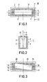
- a rectangular housing 1 of a synthetic resin in which housing two pairs of resilient lugs 4, 5 and 6, 7 extend from opposite longitudinal walls 2 and 3 of the housing 1 are pairwise opposite to each other.
- the lugs 4 and 5 which extend from the wall 2, converge inwardly and so do the lugs 6 and 7 which extend from the wall 3.
- the lugs ensure the two- sided centring of the connection wires 8 and 9 of a capacitor cell 10 which is placed in the housing 1.
- the cell 10 is embedded in a synthetic resin moulding mass 11 and secured thereby to the housing 1.
- the lugs 4, 5, 6 and 7 are resilient so that compensation can be made for variations in the length of the cell 10.
- the resilient lugs ensure that the cell 10 during moulding and optional transport is clamped in the housing 1 so that its position in the housing 1 cannot change.
- the housing 1 and the resilient lugs 4, 5, 6 and 7 may be integrally moulded from a synthetic resin.
Landscapes
- Engineering & Computer Science (AREA)
- Microelectronics & Electronic Packaging (AREA)
- Power Engineering (AREA)
- Structures For Mounting Electric Components On Printed Circuit Boards (AREA)
- Details Of Connecting Devices For Male And Female Coupling (AREA)
- Casings For Electric Apparatus (AREA)
- Coupling Device And Connection With Printed Circuit (AREA)
- Electric Double-Layer Capacitors Or The Like (AREA)
Applications Claiming Priority (2)
| Application Number | Priority Date | Filing Date | Title |
|---|---|---|---|
| NL8301046 | 1983-03-24 | ||
| NL8301046A NL8301046A (nl) | 1983-03-24 | 1983-03-24 | Electrisch bouwelement met aansluitdraden die tweezijdig in een huis gecentreerd zijn. |
Publications (2)
| Publication Number | Publication Date |
|---|---|
| EP0120540A1 true EP0120540A1 (fr) | 1984-10-03 |
| EP0120540B1 EP0120540B1 (fr) | 1987-08-05 |
Family
ID=19841595
Family Applications (1)
| Application Number | Title | Priority Date | Filing Date |
|---|---|---|---|
| EP84200406A Expired EP0120540B1 (fr) | 1983-03-24 | 1984-03-21 | Composant électrique comportant un élément de circuit électrique dont les fils sont centrés par rapport aux parois d'un boîtier |
Country Status (11)
| Country | Link |
|---|---|
| US (1) | US4546209A (fr) |
| EP (1) | EP0120540B1 (fr) |
| JP (1) | JPS59155729U (fr) |
| KR (1) | KR910001716B1 (fr) |
| BR (1) | BR8401312A (fr) |
| CA (1) | CA1208321A (fr) |
| DE (1) | DE3465218D1 (fr) |
| ES (1) | ES286547Y (fr) |
| FI (1) | FI78191C (fr) |
| HK (1) | HK34788A (fr) |
| NL (1) | NL8301046A (fr) |
Citations (4)
| Publication number | Priority date | Publication date | Assignee | Title |
|---|---|---|---|---|
| FR2110871A5 (fr) * | 1970-10-02 | 1972-06-02 | Int Standard Electric Corp | |
| EP0062167A2 (fr) * | 1981-03-31 | 1982-10-13 | Siemens Aktiengesellschaft | Composant électrique centré et ajusté dans un boîtier |
| DE3112833A1 (de) * | 1981-03-31 | 1982-10-14 | Siemens AG, 1000 Berlin und 8000 München | Elektrisches bauelement, das zentriert und justiert in einem gehaeuse untergebracht ist |
| DE3130837A1 (de) * | 1981-08-04 | 1983-02-24 | Ernst Roederstein Spezialfabrik für Kondensatoren GmbH, 8300 Landshut | Elektrisches bauteil |
Family Cites Families (11)
| Publication number | Priority date | Publication date | Assignee | Title |
|---|---|---|---|---|
| GB567588A (en) * | 1943-08-09 | 1945-02-21 | Percy Archibald Sporing | Improvements in or relating to electrical condensers |
| US2606215A (en) * | 1948-11-26 | 1952-08-05 | Weston Electrical Instr Corp | Encased and hermetically sealed photocell |
| US2885522A (en) * | 1957-07-01 | 1959-05-05 | Sprague Electric Co | Electrical component and casting arrangement |
| US3250969A (en) * | 1964-07-29 | 1966-05-10 | Western Electric Co | Encapsulated capacitor |
| US3440589A (en) * | 1966-04-01 | 1969-04-22 | Brunswick Corp | Resistor unit and method of making same |
| BE780341A (fr) * | 1972-03-08 | 1972-09-08 | Acec | Condensateur |
| DE2305484C3 (de) * | 1973-02-05 | 1978-08-24 | Siemens Ag, 1000 Berlin Und 8000 Muenchen | Erregereinrichtung für eine gleichstromerregte Drehstrom-Lichtmaschine |
| US4114008A (en) * | 1976-06-14 | 1978-09-12 | Teltec, Incorporated | Relay seal cap |
| DE2802688A1 (de) * | 1978-01-21 | 1979-07-26 | Bosch Gmbh Robert | Elektrischer kleinkondensator |
| JPS5527922U (fr) * | 1978-08-11 | 1980-02-22 | ||
| US4317158A (en) * | 1980-03-03 | 1982-02-23 | Sprague Electric Company | AC Capacitor |
-
1983
- 1983-03-24 NL NL8301046A patent/NL8301046A/nl not_active Application Discontinuation
-
1984
- 1984-03-13 US US06/589,242 patent/US4546209A/en not_active Expired - Lifetime
- 1984-03-21 EP EP84200406A patent/EP0120540B1/fr not_active Expired
- 1984-03-21 FI FI841137A patent/FI78191C/fi not_active IP Right Cessation
- 1984-03-21 BR BR8401312A patent/BR8401312A/pt not_active IP Right Cessation
- 1984-03-21 DE DE8484200406T patent/DE3465218D1/de not_active Expired
- 1984-03-21 CA CA000450094A patent/CA1208321A/fr not_active Expired
- 1984-03-21 ES ES1984286547U patent/ES286547Y/es not_active Expired
- 1984-03-22 JP JP1984041191U patent/JPS59155729U/ja active Granted
- 1984-03-22 KR KR1019840001475A patent/KR910001716B1/ko not_active Expired
-
1988
- 1988-05-12 HK HK347/88A patent/HK34788A/xx unknown
Patent Citations (4)
| Publication number | Priority date | Publication date | Assignee | Title |
|---|---|---|---|---|
| FR2110871A5 (fr) * | 1970-10-02 | 1972-06-02 | Int Standard Electric Corp | |
| EP0062167A2 (fr) * | 1981-03-31 | 1982-10-13 | Siemens Aktiengesellschaft | Composant électrique centré et ajusté dans un boîtier |
| DE3112833A1 (de) * | 1981-03-31 | 1982-10-14 | Siemens AG, 1000 Berlin und 8000 München | Elektrisches bauelement, das zentriert und justiert in einem gehaeuse untergebracht ist |
| DE3130837A1 (de) * | 1981-08-04 | 1983-02-24 | Ernst Roederstein Spezialfabrik für Kondensatoren GmbH, 8300 Landshut | Elektrisches bauteil |
Also Published As
| Publication number | Publication date |
|---|---|
| FI841137A0 (fi) | 1984-03-21 |
| EP0120540B1 (fr) | 1987-08-05 |
| BR8401312A (pt) | 1984-10-30 |
| JPS59155729U (ja) | 1984-10-19 |
| JPH0328500Y2 (fr) | 1991-06-19 |
| KR840008520A (ko) | 1984-12-15 |
| US4546209A (en) | 1985-10-08 |
| FI841137L (fi) | 1984-09-25 |
| KR910001716B1 (ko) | 1991-03-19 |
| CA1208321A (fr) | 1986-07-22 |
| ES286547U (es) | 1985-11-01 |
| NL8301046A (nl) | 1984-10-16 |
| DE3465218D1 (en) | 1987-09-10 |
| ES286547Y (es) | 1986-06-01 |
| FI78191B (fi) | 1989-02-28 |
| FI78191C (fi) | 1989-06-12 |
| HK34788A (en) | 1988-05-20 |
Similar Documents
| Publication | Publication Date | Title |
|---|---|---|
| KR100804841B1 (ko) | 집적 커패시터를 갖는 홀 효과 센서 어셈블리 및 그 제조 방법 | |
| US3806766A (en) | Packaged electrical component assembly and method of fabrication | |
| US3251015A (en) | Miniature magnetic core and component assemblies | |
| KR101831379B1 (ko) | 평평한 도전성 트랙, 자기 코어 및 자기 전자 각도 센서를 갖는 전자기 코일 구조 | |
| US4704592A (en) | Chip inductor electronic component | |
| US6005463A (en) | Through-hole interconnect device with isolated wire-leads and component barriers | |
| US4263479A (en) | Terminated inductive coil assembly | |
| EP0320013B1 (fr) | Condensateur du type pastille et procédé de fabrication | |
| US3222450A (en) | Encapsulating for electrical component and terminal means for use therewith | |
| EP0120540B1 (fr) | Composant électrique comportant un élément de circuit électrique dont les fils sont centrés par rapport aux parois d'un boîtier | |
| CN113745002B (zh) | 电子部件 | |
| ES340296A1 (es) | Perfeccionamientos en bobinados electricos de conductores laminares para maquinas electricas. | |
| JPH053724B2 (fr) | ||
| EP3783776B1 (fr) | Support de bobine pour moteur électrique | |
| US5262745A (en) | Surface mounted multi-section bobbin | |
| EP0408289B1 (fr) | Unité de condensation antibruit pour générateur de véhicules | |
| EP0071306A1 (fr) | Baleine électrique | |
| JPS58134416A (ja) | コンデンサ | |
| RU2398299C2 (ru) | Электронный компонент и способ его крепления | |
| JP2599088Y2 (ja) | 表面実装型ノイズフィルタ | |
| JPH0115158Y2 (fr) | ||
| JPS6133613Y2 (fr) | ||
| JPS61113223A (ja) | リ−ドレス型電解コンデンサ | |
| JPS5934111Y2 (ja) | リ−ドレス電子部品の接続構造 | |
| SU421089A1 (ru) | Статор электрической машины |
Legal Events
| Date | Code | Title | Description |
|---|---|---|---|
| PUAI | Public reference made under article 153(3) epc to a published international application that has entered the european phase |
Free format text: ORIGINAL CODE: 0009012 |
|
| AK | Designated contracting states |
Designated state(s): CH DE FR GB IT LI NL SE |
|
| 17P | Request for examination filed |
Effective date: 19841120 |
|
| 17Q | First examination report despatched |
Effective date: 19860514 |
|
| GRAA | (expected) grant |
Free format text: ORIGINAL CODE: 0009210 |
|
| AK | Designated contracting states |
Kind code of ref document: B1 Designated state(s): CH DE FR GB IT LI NL SE |
|
| REF | Corresponds to: |
Ref document number: 3465218 Country of ref document: DE Date of ref document: 19870910 |
|
| ITF | It: translation for a ep patent filed | ||
| ET | Fr: translation filed | ||
| PLBE | No opposition filed within time limit |
Free format text: ORIGINAL CODE: 0009261 |
|
| STAA | Information on the status of an ep patent application or granted ep patent |
Free format text: STATUS: NO OPPOSITION FILED WITHIN TIME LIMIT |
|
| 26N | No opposition filed | ||
| PG25 | Lapsed in a contracting state [announced via postgrant information from national office to epo] |
Ref country code: LI Effective date: 19890331 Ref country code: CH Effective date: 19890331 |
|
| REG | Reference to a national code |
Ref country code: CH Ref legal event code: PL |
|
| PGFP | Annual fee paid to national office [announced via postgrant information from national office to epo] |
Ref country code: NL Payment date: 19900331 Year of fee payment: 7 |
|
| PGFP | Annual fee paid to national office [announced via postgrant information from national office to epo] |
Ref country code: SE Payment date: 19910326 Year of fee payment: 8 |
|
| PG25 | Lapsed in a contracting state [announced via postgrant information from national office to epo] |
Ref country code: NL Effective date: 19911001 |
|
| NLV4 | Nl: lapsed or anulled due to non-payment of the annual fee | ||
| PG25 | Lapsed in a contracting state [announced via postgrant information from national office to epo] |
Ref country code: SE Effective date: 19920322 |
|
| ITTA | It: last paid annual fee | ||
| EUG | Se: european patent has lapsed |
Ref document number: 84200406.1 Effective date: 19921005 |
|
| PGFP | Annual fee paid to national office [announced via postgrant information from national office to epo] |
Ref country code: GB Payment date: 19950228 Year of fee payment: 12 |
|
| ITPR | It: changes in ownership of a european patent |
Owner name: CAMBIO RAGIONE SOCIALE;PHILIPS ELECTRONICS N.V. |
|
| REG | Reference to a national code |
Ref country code: FR Ref legal event code: CD |
|
| PG25 | Lapsed in a contracting state [announced via postgrant information from national office to epo] |
Ref country code: GB Effective date: 19960321 |
|
| GBPC | Gb: european patent ceased through non-payment of renewal fee |
Effective date: 19960321 |
|
| REG | Reference to a national code |
Ref country code: FR Ref legal event code: CD |
|
| PGFP | Annual fee paid to national office [announced via postgrant information from national office to epo] |
Ref country code: FR Payment date: 20010326 Year of fee payment: 18 |
|
| PGFP | Annual fee paid to national office [announced via postgrant information from national office to epo] |
Ref country code: DE Payment date: 20010516 Year of fee payment: 18 |
|
| PG25 | Lapsed in a contracting state [announced via postgrant information from national office to epo] |
Ref country code: DE Free format text: LAPSE BECAUSE OF NON-PAYMENT OF DUE FEES Effective date: 20021001 |
|
| PG25 | Lapsed in a contracting state [announced via postgrant information from national office to epo] |
Ref country code: FR Free format text: LAPSE BECAUSE OF NON-PAYMENT OF DUE FEES Effective date: 20021129 |
|
| REG | Reference to a national code |
Ref country code: FR Ref legal event code: ST |