EP0120598A2 - Verfahren und Einrichtung zur Anzeige eines Bildes - Google Patents
Verfahren und Einrichtung zur Anzeige eines Bildes Download PDFInfo
- Publication number
- EP0120598A2 EP0120598A2 EP84301143A EP84301143A EP0120598A2 EP 0120598 A2 EP0120598 A2 EP 0120598A2 EP 84301143 A EP84301143 A EP 84301143A EP 84301143 A EP84301143 A EP 84301143A EP 0120598 A2 EP0120598 A2 EP 0120598A2
- Authority
- EP
- European Patent Office
- Prior art keywords
- spiral
- raster
- spiral raster
- picture
- screen
- Prior art date
- Legal status (The legal status is an assumption and is not a legal conclusion. Google has not performed a legal analysis and makes no representation as to the accuracy of the status listed.)
- Granted
Links
Images

Classifications
-
- G—PHYSICS
- G09—EDUCATION; CRYPTOGRAPHY; DISPLAY; ADVERTISING; SEALS
- G09G—ARRANGEMENTS OR CIRCUITS FOR CONTROL OF INDICATING DEVICES USING STATIC MEANS TO PRESENT VARIABLE INFORMATION
- G09G1/00—Control arrangements or circuits, of interest only in connection with cathode-ray tube indicators; General aspects or details, e.g. selection emphasis on particular characters, dashed line or dotted line generation; Preprocessing of data
- G09G1/06—Control arrangements or circuits, of interest only in connection with cathode-ray tube indicators; General aspects or details, e.g. selection emphasis on particular characters, dashed line or dotted line generation; Preprocessing of data using single beam tubes, e.g. three-dimensional or perspective representation, rotation or translation of display pattern, hidden lines, shadows
- G09G1/14—Control arrangements or circuits, of interest only in connection with cathode-ray tube indicators; General aspects or details, e.g. selection emphasis on particular characters, dashed line or dotted line generation; Preprocessing of data using single beam tubes, e.g. three-dimensional or perspective representation, rotation or translation of display pattern, hidden lines, shadows the beam tracing a pattern independent of the information to be displayed, this latter determining the parts of the pattern rendered respectively visible and invisible
- G09G1/18—Control arrangements or circuits, of interest only in connection with cathode-ray tube indicators; General aspects or details, e.g. selection emphasis on particular characters, dashed line or dotted line generation; Preprocessing of data using single beam tubes, e.g. three-dimensional or perspective representation, rotation or translation of display pattern, hidden lines, shadows the beam tracing a pattern independent of the information to be displayed, this latter determining the parts of the pattern rendered respectively visible and invisible a small local pattern covering only a single character, and stepping to a position for the following character, e.g. in rectangular or polar co-ordinates, or in the form of a framed star
-
- G—PHYSICS
- G09—EDUCATION; CRYPTOGRAPHY; DISPLAY; ADVERTISING; SEALS
- G09G—ARRANGEMENTS OR CIRCUITS FOR CONTROL OF INDICATING DEVICES USING STATIC MEANS TO PRESENT VARIABLE INFORMATION
- G09G1/00—Control arrangements or circuits, of interest only in connection with cathode-ray tube indicators; General aspects or details, e.g. selection emphasis on particular characters, dashed line or dotted line generation; Preprocessing of data
- G09G1/06—Control arrangements or circuits, of interest only in connection with cathode-ray tube indicators; General aspects or details, e.g. selection emphasis on particular characters, dashed line or dotted line generation; Preprocessing of data using single beam tubes, e.g. three-dimensional or perspective representation, rotation or translation of display pattern, hidden lines, shadows
- G09G1/14—Control arrangements or circuits, of interest only in connection with cathode-ray tube indicators; General aspects or details, e.g. selection emphasis on particular characters, dashed line or dotted line generation; Preprocessing of data using single beam tubes, e.g. three-dimensional or perspective representation, rotation or translation of display pattern, hidden lines, shadows the beam tracing a pattern independent of the information to be displayed, this latter determining the parts of the pattern rendered respectively visible and invisible
Definitions
- This invention relates to a method of and an apparatus for displaying a picture by scanning an electron beam along a spiral raster on a screen in the case where a picture is displayed by the steps of: scanning on the screen such as a cathode ray tube by the electron beam; changing intensity of the electron beam which changes the luminance of each light spot to be generated on the screen. More concretely, this invention relates to a method of producing a pattern on the screen of a video gaming machine and the like by the above-mentioned spiral raster scanning method and of very freely moving, rotating, modifying, enlarging or reducing that pattern at any time, and to an apparatus for embodying the method.
- One well-known method of generating those patterns is to use parallel raster scanning method which is similar to the case of a standard TV receiver, and the other one is a random scanning or vector generating method.
- each scan line is divided into a number of picture display elements and the luminance of each picture element is controlled; as a result, a picture is displayed as a mosaic pattern consisting of a series of picture elements along the scan line.
- the X-Y deflection angles of the electron beam are controlled without using any raster, thereby drawing a line image on the screen.
- the gist of the present invention is that: at least one starting point is determined on the screen; pictures are produced on spiral rasters which diverge from each of the above-mentioned starting points or which converge to each of the starting points; the shapes, -phases, linear densities, and scanning speeds of each of those spiral rasters are controlled; thereby the patterns displayed on the screen are moved, rotated, enlarged, reduced or modified.
- the central position of this spiral raster is given by setting deflection control signals in the X and Y directions of the electron beam into fixed values.
- the spiral raster is produced by adding a sine wave whose amplitude gradually increases or decreases to the above-mentioned deflection control signals.
- the scanning operation is performed at a constant angular velocity.
- the frequencies are changed in proportion to the amplitudes, the scanning operation can be done at a constant velocity.
- the spiral raster is divided into a number of segments and a peculiar address and a luminance data corresponding to its address are given to each segment respectively, thereby forming a video-signal to control an intensity of the electron beam and controlling the intensity of the electron beam for every segment synchronously with the scanning operation, and as a result of it, the luminance of the above segment is controlled and a pattern is displayed.
- a known spiral raster scanning TV the picture is scanned along a circular or elliptical spiral which diverges outwardly from the central point of the CRT screen or which converges inwardly toward the central point of the screen from the outside, thereby forming a picture on the whole screen or its central portion which is similar to the picture that will be displayed by an ordinary parallel line raster scanning method.
- a technology is not yet known whereby particular patterns or characters can be generated in required positions at any time and their movement, rotation, etc. are performed by controlling the phase or the like of the. sine wave signal for deflecting the electron beam.
- Expression (3) can be also written like following expression (4).
- signals X(t) and Y(t) for deflecting the electron beam in the X and Y directions are represented by following expression (5) or (6) wherein X 0 , Y 0 , ⁇ 1 , and ⁇ 2 are constants, t is a time ( 0 ⁇ t ⁇ t 0 ), and F 1 (t), 'F 2 (t) ⁇ 1 (t), and ⁇ 2 (t) are functions with respect to the time.
- the point (X 0 , Y 0 ) is the central point of the spiral raster and the spiral raster together with the pattern can be in parallel motion by sequentially changing the values of these X 0 and Y 0 .
- the pattern can be rotated around the central point of the spiral raster by changing the phase difference of the sine wave signal portion.
- the raster can be modified from circle to ellipse and further to a linear shape, and vice versa by changing the phase difference ( ⁇ 1 - ⁇ 2 ).
- the pattern displayed can be enlarged, reduced, or modified by-controlling the amplitudes F 1 (t) and F 2 (t).
- spiral raster which can be used in the present invention is not limited only to the spirals shown by the above-mentioned expressions. However, of course, it may be possible to use and pseudo-spiral which is constituted by combining circular arcs as will be described later, - shaped or elliptic spiral, and other more complicated spirals whose interlinear distances or the like are not constant.
- Expressions (7) represent a circular vibration in which the radius increases in proportion to the time and they represent the spiral raster which diverges from the point (X 0 , Y 0 ).
- 2 ⁇ F 0 / ⁇ 0 is an interlinear distance and ⁇ is a parameter indicative of its phase.
- This spiral raster consists of semicircular arcs of which the radius increases up to F at every semicircle.
- This spiral is such that the interlinear distance is ⁇ F and the angular velocity for the central point of the point [X(t), Y(t)) which moves along the spiral raster is a constant value W 0 and that the speed at which that point leaves from the central point is ⁇ F ⁇ 0 2 ⁇ .
- This spiral raster moves in association with continuous changes of X 0 and Y 0 in the above expressions as functions of the time substantially similar to that shown'in Figs. 1 and 2.
- this raster can be generated by the apparatus of the present invention and it has an effect similar to that of the present invention.
- electron beam deflection signals in the X and Y directions are given by the sine waves of which the amplitudes and/or cycles fluctuate.
- Such a sine wave signal method not only causes a saw tooth wave generator and a synchronizing signal which are indispensable for an ordinary parallel line raster to become unnecessary but also allows the electron beam to be easily deflected.
- Such a sine signal wave of which the amplitude and/or cycle fluctuates can be also easily obtained by an analog technique such as an amplitude modulation, frequency modulation, or the like or by a hybrid technique such as pulse width modulation or the like from an ordinary sine wave or square wave pulse train.
- a most desirable method is that a desired criterion function X(t) is coded and is recorded in an ROM and this is read out if necessary, then a desired processing is performed to this, thereby obtaining a necessary control signal.
- the spiral raster is divided by the equiangle from the central point, so that the picture displaying elements on the spiral raster consist of microcircular arcs each having a constant central angle.
- this method is suitable for representation of the radial pattern, it is not always optimum for the representation of a pattern whose outline is constituted by the horizontal lines and .vertical lines.
- This method can be improved by a technique in that the spiral raster is divided into circular arcs each having a constant length or the outside of the spiral raster is divided more minutely by smaller dividing angle or the like.
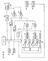
- a reference numeral 1 denotes a central- processing-unit (hereinafter, refered to as "CPU”); 2 is a read-only- memory (hereinafter, referred to as "ROM”) in which programs and picture data or the like necessary for the display have been recorded; 3 is an random-access-memory (hereinbelow, referred to as an RAM) which is used at any time while in the operation; 4 is a spiral raster generator consisting of an ROM 5 for generating criterion functions, a criterion function registers 6, 7, 8, and 9, and multipliers 10 and 11; 12 is a magnification setting device; 13, 14, 15, and 16 are digital-to-analog converters; 17 and 18 are adders; 19 is a video signal generator; 20 is a CRT display; 21 is a console for operation; and 22 is an encoder.
- CPU central- processing-unit
- ROM read-only- memory
- 3 is an random-access-memory (hereinbelow, referred to as an RAM
- the CPU 1 takes in the necessary data from the ROM 2 and generates control signals necessary for display in response to an input from the console 21.
- These control signals consist of firstly a raster generation signal group which is sent to the spiral raster generator 4, magnification setting device 12, and digital-to-analog converters 15 and 16 respectively, and secondly a video control signal train which is sent to the video signal generator 19.
- criterion functions have been recorded in the ROM 5 acting as a criterion function generator, and its data is read out with a phase difference to be given from the CPU 1 for every function during the period when one spiral raster is being scanned.
- the multipliers 10 and 11 respectively perform the multiplications such as
- the D/A converters 13 and 14 convert these inputs into the analog values, the conversion magnifications are given by the CPU 1 and their outputs respectively corresponding to the sine wave portions of expressions (7), i.e.
- the values of the central point (X O2 Y 0 ) of the raster are also simultaneously given from the CPU 1 and are converted into the analog values by the D/A converters 15 and 16. These values are then added to the outputs of the D/A converters 13 and 14 by the adders 17 and 18, so that the outputs shown in expressions (7) are obtained, i.e.
- the video signal generator 19 generates a required video signal synchronously with the generation of the previously mentioned spiral raster.
- the outputs of the adders 17 and 18 are added to the deflection coil of the CRT display 20 and the output of the video signal generator 19 is given to the control grid.
- the deflection coil circuit is a LR circuit
- a phase difference appears between applied voltage across deflection coil and real current through said coil, therefore said video signals should not be synchronized with said applied voltage for deflection coil control but said current.
- Said delay of phase is in proportion to frequency of deflection coil voltage waves, and in the case of constant tangental velocity scanning, said frequency is in inverse ratio to a radius of spiral scan line, therefore said difference in phase, in the end, is inversely proportional to radius of spiral scan line.
- out put signals of the video signal generator 19 are synchronously generated with said applied voltage across the deflection coil, said out put signals should be given to the control grid of CRT 20 after a delay time which equal to said time lag, otherwise, the displayed pattern might be distorted.
- Said delay of time might be given by a delay circuit which inserted between the video signal generator 19 and the control grid of CRT 20, or by delaying output signal of CPU 1 for controlling the video signal generator 19.
- the raster moves when the numeric values to be given from the CPU 1 to the D/A converters 15 and 16 change; the pattern is enlarged or reduced when the magnification to be given to the magnification setting device 12 changes; and the pattern rotates with the raster by changing the value of (t l - t 2 ) mentioned before.
- the present invention is constituted as described above, according to the present invention, a number of colorful and brilliant patterns can be simultaneously generated on the CRT display and these patterns can be freely moved, enlarged, reduced, and rotated by a simple circuit constitution.
- the constitution of the present invention is not limited to the above-described embodiments.
- the gist of the present invention is that: the horizontal and vertical deflections are controlled by the sine waves; the amplitudes, frequencies and phase difference of them are controlled; thereby producing a spiral raster and then arbitrarily moving, enlarging, reducing, and rotating it. Therefore, it is possible to freely change the technical means with respect to the method of generating sine waves, controlling method, shapes of rasters, etc. whithin the range of the objects of the present invention.
Landscapes
- Engineering & Computer Science (AREA)
- Radar, Positioning & Navigation (AREA)
- Remote Sensing (AREA)
- Physics & Mathematics (AREA)
- Computer Hardware Design (AREA)
- General Physics & Mathematics (AREA)
- Theoretical Computer Science (AREA)
- Controls And Circuits For Display Device (AREA)
- Digital Computer Display Output (AREA)
Applications Claiming Priority (2)
| Application Number | Priority Date | Filing Date | Title |
|---|---|---|---|
| JP31018/83 | 1983-02-28 | ||
| JP58031018A JPS59157689A (ja) | 1983-02-28 | 1983-02-28 | 画像表示方法及び装置 |
Publications (3)
| Publication Number | Publication Date |
|---|---|
| EP0120598A2 true EP0120598A2 (de) | 1984-10-03 |
| EP0120598A3 EP0120598A3 (en) | 1986-06-11 |
| EP0120598B1 EP0120598B1 (de) | 1990-12-12 |
Family
ID=12319786
Family Applications (1)
| Application Number | Title | Priority Date | Filing Date |
|---|---|---|---|
| EP84301143A Expired - Lifetime EP0120598B1 (de) | 1983-02-28 | 1984-02-22 | Verfahren und Einrichtung zur Anzeige eines Bildes |
Country Status (4)
| Country | Link |
|---|---|
| US (1) | US4746916A (de) |
| EP (1) | EP0120598B1 (de) |
| JP (1) | JPS59157689A (de) |
| DE (1) | DE3483728D1 (de) |
Cited By (2)
| Publication number | Priority date | Publication date | Assignee | Title |
|---|---|---|---|---|
| AU743334B2 (en) * | 1998-08-28 | 2002-01-24 | Canon Kabushiki Kaisha | Method and apparatus for orientating a character stroke |
| US6937239B1 (en) | 1998-08-28 | 2005-08-30 | Canon Kabushiki Kaisha | Method and apparatus for orientating a character stroke |
Families Citing this family (6)
| Publication number | Priority date | Publication date | Assignee | Title |
|---|---|---|---|---|
| US5233335A (en) * | 1989-06-22 | 1993-08-03 | Hughes Aircraft Company | Symbol/raster generator for CRT display |
| JP2908002B2 (ja) * | 1990-11-26 | 1999-06-21 | 株式会社日立製作所 | 補助線表示機能を備えた作図装置、及び、その作図装置を用いた作図方法 |
| US5710839A (en) * | 1994-04-20 | 1998-01-20 | Eastman Kodak Company | Method and apparatus for obscuring features of an image |
| US20030064807A1 (en) * | 2001-09-25 | 2003-04-03 | Walker Jay S. | Method and apparatus for linked play gaming |
| CN112153384B (zh) * | 2020-07-23 | 2024-05-17 | 西安万像电子科技有限公司 | 图像编解码方法及装置 |
| WO2022036008A1 (en) * | 2020-08-11 | 2022-02-17 | Duke University | Hybrid spiral scan patterns |
Family Cites Families (13)
| Publication number | Priority date | Publication date | Assignee | Title |
|---|---|---|---|---|
| US31200A (en) * | 1861-01-22 | I H S White | Newspaper-file | |
| US2469895A (en) * | 1947-02-12 | 1949-05-10 | Rca Corp | Cathode-ray beam deflection circuit |
| US3006994A (en) * | 1957-01-26 | 1961-10-31 | Grundig Max | Television pickup camera with spiral scanning and beam intensity modulation proportional to deflection velocity |
| US3380028A (en) * | 1965-03-25 | 1968-04-23 | Navy Usa | Multi-sensor display apparatus |
| US3716842A (en) * | 1971-05-05 | 1973-02-13 | Ibm | System and method for the continuous movement of a sheet having graphic subject matter thereon through a window of a display screen |
| US3979742A (en) * | 1972-09-29 | 1976-09-07 | Harris-Intertype Corporation | Apparatus for generating graphical configurations |
| US3980926A (en) * | 1974-01-30 | 1976-09-14 | Honeywell Inc. | Spiral scan display apparatus with transient suppression means |
| USRE31200F1 (en) | 1976-01-19 | 1990-05-29 | Raster scan display apparatus for dynamically viewing image elements stored in a random access memory array | |
| NL158938B (nl) * | 1976-02-16 | 1978-12-15 | Hollandse Signaalapparaten Bv | Digitaal aftast-conversiesysteem. |
| JPS5484494A (en) * | 1977-12-19 | 1979-07-05 | Mitsubishi Electric Corp | Display unit |
| JPS5561841A (en) * | 1978-11-01 | 1980-05-09 | Hitachi Denshi Ltd | Simulated video production system by digital system |
| NL8002171A (nl) * | 1980-04-15 | 1981-11-16 | Hollandse Signaalapparaten Bv | Digitaal aftast-conversiesysteem. |
| US4415928A (en) * | 1981-01-26 | 1983-11-15 | Rca Corporation | Calculation of radial coordinates of polar-coordinate raster scan |
-
1983
- 1983-02-28 JP JP58031018A patent/JPS59157689A/ja active Granted
-
1984
- 1984-02-22 EP EP84301143A patent/EP0120598B1/de not_active Expired - Lifetime
- 1984-02-22 DE DE8484301143T patent/DE3483728D1/de not_active Expired - Lifetime
-
1987
- 1987-04-30 US US07/045,762 patent/US4746916A/en not_active Expired - Lifetime
Cited By (2)
| Publication number | Priority date | Publication date | Assignee | Title |
|---|---|---|---|---|
| AU743334B2 (en) * | 1998-08-28 | 2002-01-24 | Canon Kabushiki Kaisha | Method and apparatus for orientating a character stroke |
| US6937239B1 (en) | 1998-08-28 | 2005-08-30 | Canon Kabushiki Kaisha | Method and apparatus for orientating a character stroke |
Also Published As
| Publication number | Publication date |
|---|---|
| JPH0430032B2 (de) | 1992-05-20 |
| EP0120598B1 (de) | 1990-12-12 |
| DE3483728D1 (de) | 1991-01-24 |
| JPS59157689A (ja) | 1984-09-07 |
| US4746916A (en) | 1988-05-24 |
| EP0120598A3 (en) | 1986-06-11 |
Similar Documents
| Publication | Publication Date | Title |
|---|---|---|
| RU2108686C1 (ru) | Система управления сведением для множества вертикальных форматов | |
| US3747087A (en) | Digitally controlled computer animation generating system | |
| US4843468A (en) | Scanning techniques using hierarchical set of curves | |
| US4212009A (en) | Smoothing a raster display | |
| US4612540A (en) | Digital display system | |
| US4850028A (en) | Image processing method and apparatus therefor | |
| US4820928A (en) | Lithography apparatus | |
| EP0120598A2 (de) | Verfahren und Einrichtung zur Anzeige eines Bildes | |
| JPH0653121B2 (ja) | 走査変換装置 | |
| JPH06109994A (ja) | 画像形成装置 | |
| JPH0419556B2 (de) | ||
| EP0345672B1 (de) | Adressgenerator | |
| JPH0453353B2 (de) | ||
| US5245413A (en) | Method and apparatus for generating a spiral curve television test pattern for testing advanced television systems | |
| US3958232A (en) | Image transformation system with variable delay | |
| US4591843A (en) | Digital display system | |
| KR100256857B1 (ko) | 화상 변환 장치 | |
| US5365599A (en) | Method and system of converting delineative pattern | |
| US3769541A (en) | Line width modulated display system | |
| US4251625A (en) | Method of producing a halftone picture by vibrating light source | |
| US2938947A (en) | Method and apparatus for transforming systems of coordinates | |
| JPH05227536A (ja) | ディジタルコンバーゼンス装置 | |
| CA1081842A (en) | Image transformation system with variable delay | |
| JPS62170287A (ja) | 刺繍機縫目デ−タ作成装置 | |
| JPS63317138A (ja) | 超音波診断装置 |
Legal Events
| Date | Code | Title | Description |
|---|---|---|---|
| PUAI | Public reference made under article 153(3) epc to a published international application that has entered the european phase |
Free format text: ORIGINAL CODE: 0009012 |
|
| AK | Designated contracting states |
Designated state(s): DE GB |
|
| 17P | Request for examination filed |
Effective date: 19841010 |
|
| PUAL | Search report despatched |
Free format text: ORIGINAL CODE: 0009013 |
|
| AK | Designated contracting states |
Kind code of ref document: A3 Designated state(s): DE GB |
|
| 17Q | First examination report despatched |
Effective date: 19881223 |
|
| GRAA | (expected) grant |
Free format text: ORIGINAL CODE: 0009210 |
|
| AK | Designated contracting states |
Kind code of ref document: B1 Designated state(s): DE GB |
|
| REF | Corresponds to: |
Ref document number: 3483728 Country of ref document: DE Date of ref document: 19910124 |
|
| PLBE | No opposition filed within time limit |
Free format text: ORIGINAL CODE: 0009261 |
|
| STAA | Information on the status of an ep patent application or granted ep patent |
Free format text: STATUS: NO OPPOSITION FILED WITHIN TIME LIMIT |
|
| 26N | No opposition filed | ||
| PGFP | Annual fee paid to national office [announced via postgrant information from national office to epo] |
Ref country code: GB Payment date: 20000223 Year of fee payment: 17 |
|
| PG25 | Lapsed in a contracting state [announced via postgrant information from national office to epo] |
Ref country code: GB Free format text: LAPSE BECAUSE OF NON-PAYMENT OF DUE FEES Effective date: 20010222 |
|
| GBPC | Gb: european patent ceased through non-payment of renewal fee |
Effective date: 20010222 |
|
| PGFP | Annual fee paid to national office [announced via postgrant information from national office to epo] |
Ref country code: DE Payment date: 20030306 Year of fee payment: 20 |