EP0120630A1 - Kondensationsverfahren in Röhren - Google Patents
Kondensationsverfahren in Röhren Download PDFInfo
- Publication number
- EP0120630A1 EP0120630A1 EP84301467A EP84301467A EP0120630A1 EP 0120630 A1 EP0120630 A1 EP 0120630A1 EP 84301467 A EP84301467 A EP 84301467A EP 84301467 A EP84301467 A EP 84301467A EP 0120630 A1 EP0120630 A1 EP 0120630A1
- Authority
- EP
- European Patent Office
- Prior art keywords
- tubes
- flow
- vapour
- tube
- condensate
- Prior art date
- Legal status (The legal status is an assumption and is not a legal conclusion. Google has not performed a legal analysis and makes no representation as to the accuracy of the status listed.)
- Withdrawn
Links
- 238000000034 method Methods 0.000 title claims abstract description 7
- 230000005494 condensation Effects 0.000 title description 3
- 238000009833 condensation Methods 0.000 title description 3
- 239000012530 fluid Substances 0.000 claims abstract description 11
- 239000002826 coolant Substances 0.000 claims abstract description 5
- 230000000694 effects Effects 0.000 description 2
- 239000000203 mixture Substances 0.000 description 2
- 230000001154 acute effect Effects 0.000 description 1
- 239000012080 ambient air Substances 0.000 description 1
- 230000009286 beneficial effect Effects 0.000 description 1
- 238000004140 cleaning Methods 0.000 description 1
- 239000007788 liquid Substances 0.000 description 1
- 238000000926 separation method Methods 0.000 description 1
- 239000013526 supercooled liquid Substances 0.000 description 1
Images
Classifications
-
- F—MECHANICAL ENGINEERING; LIGHTING; HEATING; WEAPONS; BLASTING
- F22—STEAM GENERATION
- F22B—METHODS OF STEAM GENERATION; STEAM BOILERS
- F22B37/00—Component parts or details of steam boilers
- F22B37/62—Component parts or details of steam boilers specially adapted for steam boilers of forced-flow type
- F22B37/70—Arrangements for distributing water into water tubes
- F22B37/74—Throttling arrangements for tubes or sets of tubes
-
- F—MECHANICAL ENGINEERING; LIGHTING; HEATING; WEAPONS; BLASTING
- F28—HEAT EXCHANGE IN GENERAL
- F28B—STEAM OR VAPOUR CONDENSERS
- F28B1/00—Condensers in which the steam or vapour is separate from the cooling medium by walls, e.g. surface condenser
- F28B1/06—Condensers in which the steam or vapour is separate from the cooling medium by walls, e.g. surface condenser using air or other gas as the cooling medium
-
- F—MECHANICAL ENGINEERING; LIGHTING; HEATING; WEAPONS; BLASTING
- F28—HEAT EXCHANGE IN GENERAL
- F28B—STEAM OR VAPOUR CONDENSERS
- F28B9/00—Auxiliary systems, arrangements, or devices
- F28B9/04—Auxiliary systems, arrangements, or devices for feeding, collecting, and storing cooling water or other cooling liquid
-
- F—MECHANICAL ENGINEERING; LIGHTING; HEATING; WEAPONS; BLASTING
- F28—HEAT EXCHANGE IN GENERAL
- F28F—DETAILS OF HEAT-EXCHANGE AND HEAT-TRANSFER APPARATUS, OF GENERAL APPLICATION
- F28F13/00—Arrangements for modifying heat-transfer, e.g. increasing, decreasing
- F28F13/06—Arrangements for modifying heat-transfer, e.g. increasing, decreasing by affecting the pattern of flow of the heat-exchange media
- F28F13/08—Arrangements for modifying heat-transfer, e.g. increasing, decreasing by affecting the pattern of flow of the heat-exchange media by varying the cross-section of the flow channels
Definitions
- This invention relates to a heat exchange process of the kind in which a vapour is caused to flow in parallel paths through a number of tubes, so as to transfer heat to an external fluid flowing over the outer surface of the tubes.
- the fluid within the tubes thus condenses as it gives up latent heat to the external fluid.
- This arrangement is common in air-cooled or shell and tube condensers which are often used, for example, in chemical-plants.
- the result can be that in some tubes, all of the vapour is condensed before it reaches the far end of the tube.
- Such vapour may partially condense on supercooled liquid issuing from other tubes.
- Some of the vapour which has failed to condense may also, however, enter other tubes, in which condensation is complete before reaching the far end.
- This-latter vapour then travels along such tubes in the reverse direction, and condenses. There will thus be a point in such tubes where vapour flows meet from both directions. This leads to a severe problem, in that a small proportion non-condensible gas is inevitably present in the vapour.
- this gas is caught between two flows, it is not swept out of the tube, but tends to accumulate at the meeting point, so that eventually a substantial length of the tube becomes occluded by an immobile body of non-condensing gas.
- This length of the tube thus becomes ineffective for condensing vapour, and the thermal efficiency of the heat exchanger is thus substantially reduced.
- the condensate flowing through this length of tube continues to be cooled, and in some cases may freeze leading to total occlusion of the whole tube.
- the problem is particularly acute where the vapour is at less than atmospheric pressure, since any leaks will result in an increase in the proportion of non-condensible gas present.
- the present invention provides a different solution to the problem.
- the present invention provides a heat exchange process comprising the steps of
- the restriction provided by the fluid flow restrictors should normally not be substantially more severe than necessary in order to meet the objective. This will have the effect of preventing any reverse flow of vapour into a tube from the outlet manifold.
- the restrictors will also have the effect of increasing the pressure drop in each tube, which can have a beneficial effect on flow distribution in the tubes.
- the restrictors are provided in the form of removable inserts. Cleaning of the vapour tubes is thus facilitated.
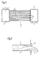
- an air-cooled heat exchanger comprises a plurality of vapour tubes 1, through which a vapour to be condensed flows from a common inlet manifold 2 to a common outlet manifold 3.
- a vapour to be condensed flows from a common inlet manifold 2 to a common outlet manifold 3.
- a supply of coolant fluid in this instance ambient air, is caused to flow over and around the exterior surfaces of the tubes 1, in the direction indicated in Fig 1 by the arrow 'A'.
- This can be arranged, for example by means of a fan, or by natural convection, and the tubes 1 can if desired be positioned within a duct for constraining the coolant flow.
- Each tube 1 is provided with a flow restrictor 4, in the form of a removable insert positioned in the downstream end of each tube.
- the inserts 4 are all identical, and the size of the restriction therein is such that for the intended conditions of operation of the heat exchanger, the flow rate of vapour in each tube 1 will result in a flow of condensate at the downstream end just sufficient to fill the restrictor substantially completely with condensate 5 (ie across its entire cross-section). If the degree of restriction is insufficient the flow of condensate will not be enough to fill the restrictor and vapour will then be able to flow back down the tube concerned in the reverse direction with the disadvantages noted hereinbefore. A greater degree of restriction can be tolerated more readily, but should be avoided as far as possible, in that any undue restriction of the flow is undesirable.
Landscapes
- Engineering & Computer Science (AREA)
- Mechanical Engineering (AREA)
- General Engineering & Computer Science (AREA)
- Physics & Mathematics (AREA)
- Thermal Sciences (AREA)
- Heat-Exchange Devices With Radiators And Conduit Assemblies (AREA)
Applications Claiming Priority (2)
| Application Number | Priority Date | Filing Date | Title |
|---|---|---|---|
| GB8307568 | 1983-03-18 | ||
| GB838307568A GB8307568D0 (en) | 1983-03-18 | 1983-03-18 | Heat exchangers |
Publications (1)
| Publication Number | Publication Date |
|---|---|
| EP0120630A1 true EP0120630A1 (de) | 1984-10-03 |
Family
ID=10539831
Family Applications (1)
| Application Number | Title | Priority Date | Filing Date |
|---|---|---|---|
| EP84301467A Withdrawn EP0120630A1 (de) | 1983-03-18 | 1984-03-06 | Kondensationsverfahren in Röhren |
Country Status (4)
| Country | Link |
|---|---|
| EP (1) | EP0120630A1 (de) |
| JP (1) | JPS6036888A (de) |
| CA (1) | CA1197209A (de) |
| GB (2) | GB8307568D0 (de) |
Cited By (2)
| Publication number | Priority date | Publication date | Assignee | Title |
|---|---|---|---|---|
| EP0488096A1 (de) * | 1990-11-29 | 1992-06-03 | Richard Vetter | Röhrenwärmeaustauscher |
| US9562722B2 (en) | 2009-03-13 | 2017-02-07 | Carrier Corporation | Manifold assembly for distributing a fluid to a heat exchanger |
Families Citing this family (5)
| Publication number | Priority date | Publication date | Assignee | Title |
|---|---|---|---|---|
| JPS6438590A (en) * | 1987-08-04 | 1989-02-08 | Toshiba Corp | Heat exchanger |
| US5113933A (en) * | 1990-10-10 | 1992-05-19 | Larinoff Michael W | Air-cooled vacuum steam condenser bundle isolation |
| DE4330361A1 (de) * | 1993-09-08 | 1995-03-09 | Richard Vetter | Röhrenwärmeaustauscher |
| JP2009222285A (ja) * | 2008-03-14 | 2009-10-01 | Tlv Co Ltd | 空気加熱装置 |
| JP2009222286A (ja) * | 2008-03-14 | 2009-10-01 | Tlv Co Ltd | 空気加熱装置 |
Citations (5)
| Publication number | Priority date | Publication date | Assignee | Title |
|---|---|---|---|---|
| FR795801A (fr) * | 1934-12-24 | 1936-03-23 | Perfectionnement aux chaudières à tubes d'eau | |
| US2310234A (en) * | 1939-09-27 | 1943-02-09 | United Eng & Constructors Inc | Gas condenser |
| US2694385A (en) * | 1952-10-06 | 1954-11-16 | Combustion Eng | Size identified mounting means for flow restricting orifices |
| FR1079141A (fr) * | 1953-04-09 | 1954-11-25 | Thermo Mecanique | Perfectionnements apportés aux faisceaux tubulaires |
| DE1811596A1 (de) * | 1968-01-15 | 1969-08-07 | Waagner Biro Ag | Verfahren und Einrichtung zur Vergleichmaessigung des Waermeueberganges |
-
1983
- 1983-03-18 GB GB838307568A patent/GB8307568D0/en active Pending
-
1984
- 1984-03-06 EP EP84301467A patent/EP0120630A1/de not_active Withdrawn
- 1984-03-09 GB GB08406204A patent/GB2137330B/en not_active Expired
- 1984-03-16 CA CA000449760A patent/CA1197209A/en not_active Expired
- 1984-03-16 JP JP4934784A patent/JPS6036888A/ja active Pending
Patent Citations (5)
| Publication number | Priority date | Publication date | Assignee | Title |
|---|---|---|---|---|
| FR795801A (fr) * | 1934-12-24 | 1936-03-23 | Perfectionnement aux chaudières à tubes d'eau | |
| US2310234A (en) * | 1939-09-27 | 1943-02-09 | United Eng & Constructors Inc | Gas condenser |
| US2694385A (en) * | 1952-10-06 | 1954-11-16 | Combustion Eng | Size identified mounting means for flow restricting orifices |
| FR1079141A (fr) * | 1953-04-09 | 1954-11-25 | Thermo Mecanique | Perfectionnements apportés aux faisceaux tubulaires |
| DE1811596A1 (de) * | 1968-01-15 | 1969-08-07 | Waagner Biro Ag | Verfahren und Einrichtung zur Vergleichmaessigung des Waermeueberganges |
Cited By (2)
| Publication number | Priority date | Publication date | Assignee | Title |
|---|---|---|---|---|
| EP0488096A1 (de) * | 1990-11-29 | 1992-06-03 | Richard Vetter | Röhrenwärmeaustauscher |
| US9562722B2 (en) | 2009-03-13 | 2017-02-07 | Carrier Corporation | Manifold assembly for distributing a fluid to a heat exchanger |
Also Published As
| Publication number | Publication date |
|---|---|
| JPS6036888A (ja) | 1985-02-26 |
| CA1197209A (en) | 1985-11-26 |
| GB8406204D0 (en) | 1984-04-11 |
| GB2137330B (en) | 1986-04-09 |
| GB8307568D0 (en) | 1983-04-27 |
| GB2137330A (en) | 1984-10-03 |
Similar Documents
| Publication | Publication Date | Title |
|---|---|---|
| US3612172A (en) | Air-cooled condenser | |
| US3710854A (en) | Condenser | |
| CN101617181B (zh) | 具有呈串联逆流布置的双通路热交换器的双回路冷却器 | |
| US9746256B2 (en) | Shell and tube heat exchanger with a vapor port | |
| CN1086226C (zh) | 具有整体式叠置通风冷凝器的蒸汽冷凝组件 | |
| EP1023567B1 (de) | Luftgekühlter kondensator | |
| US4513813A (en) | Air-cooled steam condenser | |
| US3543843A (en) | Air cooled condenser apparatus | |
| US4928753A (en) | Heat exchanger | |
| US3830293A (en) | Tube and shell heat exchangers | |
| US4274481A (en) | Dry cooling tower with water augmentation | |
| US3705621A (en) | Air-cooled heat exchanger | |
| EP4279849B1 (de) | Dampfwärmetauscher | |
| EP0545366A1 (de) | Luftgekühlter Vakuum-Dampfkondensator mit Kleinbündeln mit Ausgleich des Durchflusses | |
| CA1197209A (en) | In-tube condensation process | |
| US4458750A (en) | Inlet header flow distribution | |
| US3424235A (en) | Air-cooled condenser with provision for prevention of condensate freezing | |
| JPS5773392A (en) | Corrugated fin type heat exchanger | |
| US4417619A (en) | Air-cooled heat exchanger | |
| US4224981A (en) | Feed-water heater for steam power plants | |
| US3677338A (en) | Surface condenser | |
| US4537248A (en) | Air-cooled heat exchanger | |
| CN101180506A (zh) | 具有液体捕集器以提供更好流动分布的平行流蒸发器 | |
| EP0346848B1 (de) | Luftgekühlter Dampfkondensator mit Vakuum | |
| JPS5851194B2 (ja) | 乾式冷却動力プラントシステム |
Legal Events
| Date | Code | Title | Description |
|---|---|---|---|
| PUAI | Public reference made under article 153(3) epc to a published international application that has entered the european phase |
Free format text: ORIGINAL CODE: 0009012 |
|
| AK | Designated contracting states |
Designated state(s): DE FR GB IT NL SE |
|
| 17P | Request for examination filed |
Effective date: 19850129 |
|
| STAA | Information on the status of an ep patent application or granted ep patent |
Free format text: STATUS: THE APPLICATION IS DEEMED TO BE WITHDRAWN |
|
| 18D | Application deemed to be withdrawn |
Effective date: 19860602 |
|
| RIN1 | Information on inventor provided before grant (corrected) |
Inventor name: HENRY, JOHN ALEXANDER RICHARDSON |