EP0120643A2 - Monture pour un poteau - Google Patents
Monture pour un poteau Download PDFInfo
- Publication number
- EP0120643A2 EP0120643A2 EP84301671A EP84301671A EP0120643A2 EP 0120643 A2 EP0120643 A2 EP 0120643A2 EP 84301671 A EP84301671 A EP 84301671A EP 84301671 A EP84301671 A EP 84301671A EP 0120643 A2 EP0120643 A2 EP 0120643A2
- Authority
- EP
- European Patent Office
- Prior art keywords
- post
- box section
- wall
- engaging portion
- section
- Prior art date
- Legal status (The legal status is an assumption and is not a legal conclusion. Google has not performed a legal analysis and makes no representation as to the accuracy of the status listed.)
- Granted
Links
Images


Classifications
-
- E—FIXED CONSTRUCTIONS
- E04—BUILDING
- E04H—BUILDINGS OR LIKE STRUCTURES FOR PARTICULAR PURPOSES; SWIMMING OR SPLASH BATHS OR POOLS; MASTS; FENCING; TENTS OR CANOPIES, IN GENERAL
- E04H12/00—Towers; Masts or poles; Chimney stacks; Water-towers; Methods of erecting such structures
- E04H12/22—Sockets or holders for poles or posts
- E04H12/2207—Sockets or holders for poles or posts not used
- E04H12/2215—Sockets or holders for poles or posts not used driven into the ground
-
- F—MECHANICAL ENGINEERING; LIGHTING; HEATING; WEAPONS; BLASTING
- F16—ENGINEERING ELEMENTS AND UNITS; GENERAL MEASURES FOR PRODUCING AND MAINTAINING EFFECTIVE FUNCTIONING OF MACHINES OR INSTALLATIONS; THERMAL INSULATION IN GENERAL
- F16B—DEVICES FOR FASTENING OR SECURING CONSTRUCTIONAL ELEMENTS OR MACHINE PARTS TOGETHER, e.g. NAILS, BOLTS, CIRCLIPS, CLAMPS, CLIPS OR WEDGES; JOINTS OR JOINTING
- F16B2200/00—Constructional details of connections not covered for in other groups of this subclass
- F16B2200/10—Details of socket shapes
-
- Y—GENERAL TAGGING OF NEW TECHNOLOGICAL DEVELOPMENTS; GENERAL TAGGING OF CROSS-SECTIONAL TECHNOLOGIES SPANNING OVER SEVERAL SECTIONS OF THE IPC; TECHNICAL SUBJECTS COVERED BY FORMER USPC CROSS-REFERENCE ART COLLECTIONS [XRACs] AND DIGESTS
- Y10—TECHNICAL SUBJECTS COVERED BY FORMER USPC
- Y10T—TECHNICAL SUBJECTS COVERED BY FORMER US CLASSIFICATION
- Y10T403/00—Joints and connections
- Y10T403/16—Joints and connections with adjunctive protector, broken parts retainer, repair, assembly or disassembly feature
- Y10T403/1616—Position or guide means
-
- Y—GENERAL TAGGING OF NEW TECHNOLOGICAL DEVELOPMENTS; GENERAL TAGGING OF CROSS-SECTIONAL TECHNOLOGIES SPANNING OVER SEVERAL SECTIONS OF THE IPC; TECHNICAL SUBJECTS COVERED BY FORMER USPC CROSS-REFERENCE ART COLLECTIONS [XRACs] AND DIGESTS
- Y10—TECHNICAL SUBJECTS COVERED BY FORMER USPC
- Y10T—TECHNICAL SUBJECTS COVERED BY FORMER US CLASSIFICATION
- Y10T403/00—Joints and connections
- Y10T403/49—Member deformed in situ
- Y10T403/4974—Member deformed in situ by piercing
Definitions
- This invention relates to means for supporting vertical posts, for example, posts for supporting fencing or the like, sign boards, stakes for supporting plants, etc.
- UK Patent Specification No: 1461802 relates to a post support comprising an elongate ground engaging portion capable of being driven vertically into the ground and a vertical post engaging portion rigidly attached to the ground engaging portion and so formed that a post to be supported and engaged by, for example, attached to or received in, the post engaging portion extends vertically and with its axis substantially parallel to the axis of the ground engaging portion.
- the post engaging portion is a hollow box section within which the post to be erected can be received.
- Wooden posts although cut to a nominal size, are frequently over or under size and, accordingly, if the box section of the post support is dimensioned to receive a 3" post, for example, an under sized post is a loose fit in the box section and must be wedged if the post is to be supported rigidly in a vertical position and an over sized post must be planed down, or otherwise reduced in size, at the end to be received in the box section.
- a post support comprising an elongate ground engaging portion capable of being driven vertically into the ground, and a post engaging portion attached to the ground engaging portion and in the form of a hollow box section for receiving one end of a post to be supported in a vertical position and with its axis substantially parallel to the axis of the ground engaging portion wherein the hollow box section is formed with means, integral therewith, other than means for adjusting the size of the box section for enabling an under-sized post to be rigidly supported in the box section and/or for removing excess post material from an over- sized post.
- Means for removing excess material from an over- sized post preferably comprises a bevelled edge formed on the top surface of at least one wall, and preferably of two adjacent walls, of the box section, which bevelled edge(s) present(s) a chisel edge to a post being driven into the box section.
- any wall with a bevelled top surface is lower than any un-bevelled wall so that the portion of any other wall(s) extending above the bevelled edge will serve to guide the post as it is driven into the box section.
- Means for enabling an under-sized post to be rigidly supported in the box section preferably comprise an upstanding projection or plurality of projections on the inner surface of at least one wall and preferably of two adjacent walls of the box section.
- projections need only be present on one side of the box section preferably they are present on two adjacent sides, although they may be present on three, or even all four sides of a rectangular box section. In the case of a circular box section there is only a need for projections in one location on the wall, although, of course they may be present in two or more spaced locations.
- the projections are integral with the wall of the box section and may be formed by deforming the wall inwardly, for example, by pressing or they may be formed separately from the wall and adhered thereto, for example by welding.
- the projections When formed by deforming'the walls of the box section the projections may simply be pressed into the wall of the box section or they may be punched out of the wall of the box section leaving an aperture in the wall, with the cut out portion of the wall turned inwardly of the box section.
- the projections may, for example, comprise ribs or pimples or any combination thereof with corresponding grooves or dimples on the outer wall of the box section or they may comprise inwardly projecting flanges, barbs or tangs or the like punched out of the wall of the box section and optionally in combination with indented portions in the wall.
- Inwardly projecting flanges preferably extend vertically since they will then tend to cut into the post material as the post is driven into the box section. There may, however, be arranged horizontally in which case they will normally be deformed as the post is driven into the box section, or they will scrape away some of the material of the post.
- An upwardly extending tang may be provided with a bevelled edge so that the material of the post is chiselled away as the post is driven into the box section.
- the wall of the box below the tang is preferably deformed inwardly to such an extent that the groove formed in the post by the chiselled edge fits snugly over the deformed portion of the wall.
- the box section may be mounted on the ground engaging portion in such a way as to allow minor adjustment of the box section relative to the ground engaging portion after the ground engaging portion has been driven into the ground, for example, the box section may be mounted on the ground engaging portion by an arrangement similar to that shown in Specification No: GB 2111553A, or as described in our co-pending Application No: 8308486.
- the box section is rigidly attached to the ground engaging portion, for example by welding.
- the projections may be of any size or shape capable of accommodating the cutting tolerances normally found in fencing posts.
- the projections will either cut into the post or they will be deformed by the material of the post so that they do not interfere with entry of the post into the box section.
- the ground engaging portion may be of any desired configuration but is preferably of cruciform section, which may be a trifin cross but is preferably a saltire.
- the arms of the sal-tire preferably extend diagonally of a rectangular box section.
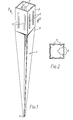
- the post support comprises a ground engaging portion 1 and a post engaging portion 2 of hollow rectangular box section.
- the ground engaging portion 1 is of cruciform cross section and tapers from the top end 3 at which the post engaging portion 2 is located to the free end 4.
- Each wall of the box section is provided with two spaced apart inwardly depressed portions 5 forming a depression 6 on the outside wall and a projection 7 on the inner wall.
- the projections extend vertically from a point adjacent the closed end 3 of the box to a point adjacent the open end of the box.
- the projections 5 may extend from a point about 1" above the base to a point about 1" below the open end.
- the box section 2 will have an internal cross section with 3" long sides and a projection is, for example, formed with a centre approximately 1" from each corner and hence the projections on each side are spaced by approximately 2".
- each wall of the box section 2 is an inwardly depressed portion 8, which is stamped out of the wall by cutting round three sides of a rectangular portion.
- the top edge 9 of each portion 8 is provided with a bevelled cutting edge.
- the post support is similar to that shown in Figs. 3 and 4 except that inwardly depressed portions 8 are formed on only two adjacent sides of the box section 2, and the height of these depressed portions 8 is reduced.
- an indented portion 10 of width equal to that of the portion 8 and able to be received within the channel section cut out of a post by the bevelled cutting edge 9 of the portion 8.
- each of two adjacent walls of the box section 2 are four stamped out portions 11. These portions 11 are each formed by making two horizontal cuts and a vertical cut extending between the midway points of the horizontal cuts and then pressing the two tabs 12 that are so formed inwardly of the box until they extend perpendicular to the walls.
- each stamped out portion 11 forms only a single tab 12 instead of a pair of tabs.
Landscapes
- Engineering & Computer Science (AREA)
- Architecture (AREA)
- Civil Engineering (AREA)
- Structural Engineering (AREA)
- Fencing (AREA)
- Housing For Livestock And Birds (AREA)
- Supports Or Holders For Household Use (AREA)
Applications Claiming Priority (8)
| Application Number | Priority Date | Filing Date | Title |
|---|---|---|---|
| GB838307009A GB8307009D0 (en) | 1983-03-14 | 1983-03-14 | Post support |
| GB8307009 | 1983-03-14 | ||
| GB838314836A GB8314836D0 (en) | 1983-05-27 | 1983-05-27 | Post support |
| GB8314836 | 1983-05-27 | ||
| GB8321322 | 1983-08-08 | ||
| GB838321322A GB8321322D0 (en) | 1983-03-14 | 1983-08-08 | Post support |
| GB08402848A GB2140057B (en) | 1983-03-14 | 1984-02-02 | Post socket |
| GB8402848 | 1984-02-02 |
Publications (3)
| Publication Number | Publication Date |
|---|---|
| EP0120643A2 true EP0120643A2 (fr) | 1984-10-03 |
| EP0120643A3 EP0120643A3 (en) | 1986-08-06 |
| EP0120643B1 EP0120643B1 (fr) | 1991-10-16 |
Family
ID=27449449
Family Applications (1)
| Application Number | Title | Priority Date | Filing Date |
|---|---|---|---|
| EP84301671A Expired - Lifetime EP0120643B1 (fr) | 1983-03-14 | 1984-03-13 | Monture pour un poteau |
Country Status (6)
| Country | Link |
|---|---|
| US (1) | US4588157A (fr) |
| EP (1) | EP0120643B1 (fr) |
| AU (1) | AU570435B2 (fr) |
| DE (1) | DE3485158D1 (fr) |
| GB (1) | GB2140057B (fr) |
| NZ (1) | NZ207486A (fr) |
Cited By (14)
| Publication number | Priority date | Publication date | Assignee | Title |
|---|---|---|---|---|
| EP0150946A3 (en) * | 1984-01-12 | 1985-08-28 | Metpost Limited | Method of making post supports |
| WO1989002962A1 (fr) * | 1987-09-23 | 1989-04-06 | Eltek Holdings Pty. Ltd. | Dispositif de support de poteau |
| WO1994004780A1 (fr) * | 1992-08-21 | 1994-03-03 | Alois Zihlmann | Dispositif de fixation au sol d'appareils |
| DE9401712U1 (de) * | 1994-02-02 | 1994-03-24 | Krinner, Klaus, 94342 Straßkirchen | Vorrichtung zum Verhindern des Lockerns von im Erdboden befestigten langgestreckten Gegenständen |
| EP0799954A1 (fr) * | 1996-04-02 | 1997-10-08 | Franz Brinkmann Metallwaren GmbH | Pieu d'ancrage avec socle pour poteau |
| NL1005588C2 (nl) * | 1997-03-20 | 1998-09-22 | Zeus Beton Bv | Paalsok en paalsamenstel met een paalsok. |
| WO2005047625A1 (fr) * | 2003-11-12 | 2005-05-26 | Fournier Paul W | Base de distribution de ligne de service |
| DE102005055401A1 (de) * | 2005-11-17 | 2007-05-24 | STÄBLER, Karl | Weinbergpfahl |
| ES2303435A1 (es) * | 2006-03-28 | 2008-08-01 | Inveral, S.A. | Dispositivo de anclaje de elementos accesorios al forjado de una obra. |
| EP2711486A1 (fr) * | 2012-09-25 | 2014-03-26 | Gebr. Sträb GmbH & Co. | Dispositif de stabilisation destiné à la stabilisation de position d'un objet en forme de tige ou d'un ancrage, procédé de fabrication d'un dispositif de stabilisation et outil de pose de fixation pour un dispositif de stabilisation |
| US10559231B2 (en) * | 2016-04-18 | 2020-02-11 | Fox Valley Realty Sign Llc | Sign post mounting apparatus |
| SE2000180A1 (sv) * | 2020-10-01 | 2022-04-02 | Fiedler Innovations Int Ab | Markförankringselement med fästanordning |
| EP4343084A1 (fr) * | 2022-09-20 | 2024-03-27 | Eurokon Global Exports Pvt. Ltd | Ancrage de poteau |
| US12123212B2 (en) | 2021-05-18 | 2024-10-22 | Staketta Ky | Post socket and a method to make a post socket |
Families Citing this family (57)
| Publication number | Priority date | Publication date | Assignee | Title |
|---|---|---|---|---|
| FR2569220B1 (fr) * | 1984-08-16 | 1986-11-28 | Moraly Paul | Cheville a fourreau rapporte destinee a la fixation dans le sol de poteaux ou piquets |
| AT387256B (de) * | 1986-02-10 | 1988-12-27 | Elin Union Ag | Einrichtung zur fundierung eines mastes |
| GB8717737D0 (en) * | 1987-07-27 | 1987-09-03 | Metpost Ltd | Post supports |
| GB8807649D0 (en) * | 1988-03-31 | 1988-05-05 | Price L M | Improvements relating to post supports |
| US4832304A (en) * | 1988-05-23 | 1989-05-23 | Tzvika Shahak | Ground-anchoring device particularly for umbrellas |
| US4874149A (en) * | 1988-09-15 | 1989-10-17 | The Gordon Corporation | Post support |
| US4932540A (en) * | 1989-04-24 | 1990-06-12 | Armstrong Store Fixture Corporation | Merchandise display fixture |
| US5090656A (en) * | 1990-02-22 | 1992-02-25 | Brown Roger A | Post support |
| AU644731B2 (en) * | 1991-04-17 | 1993-12-16 | LMI Investments Pty Ltd | Post support |
| ES2058005B1 (es) * | 1992-01-10 | 1997-09-01 | Guerenabarrena Martinez De La | Metodo para el anclaje en el suelo de postes, estacas y similares. |
| DE9204121U1 (de) * | 1992-03-27 | 1992-08-06 | Radtke, Manfred, Dipl.-Biol., 8707 Veitshöchheim | Lastverteilende Befestigungsplatte |
| GB2267102B (en) * | 1992-05-19 | 1996-05-29 | Gary Martin Price | Improvements in or relating to post supports |
| GB9211510D0 (en) * | 1992-06-01 | 1992-07-15 | Metpost Ltd | Post supports |
| AU661632B1 (en) * | 1994-07-25 | 1995-07-27 | James Fowler Hart | Locking footing socket to improve post implantation |
| US5632464A (en) * | 1995-09-05 | 1997-05-27 | Aberle; Steven C. | Ground pocket support |
| US5535555A (en) * | 1995-11-17 | 1996-07-16 | The University Foundation, California State University | Breakaway post coupling |
| AU737858B2 (en) * | 1997-03-11 | 2001-08-30 | Lapsi Pty Ltd | Surveyor's peg |
| US6039298A (en) * | 1997-09-12 | 2000-03-21 | Stier; Peter | Tapered steel post |
| US5884874A (en) * | 1997-09-25 | 1999-03-23 | Steel City Corporation | Swivel post anchor |
| US5984587A (en) * | 1997-11-06 | 1999-11-16 | Odle; Stanley W. | Ground stabilization apparatus and method for installing an enlongated post |
| US6263614B1 (en) * | 1998-07-10 | 2001-07-24 | United Chinese Plastics Products Co., Ltd. | Base for supporting artifical flowers or foliage |
| US6178651B1 (en) | 1998-11-24 | 2001-01-30 | Steven Mark Yancey | Reusable batter board support |
| AUPP787098A0 (en) * | 1998-12-23 | 1999-01-21 | Ani Corporation Limited, The | Post anchor |
| US6402115B1 (en) | 1999-08-16 | 2002-06-11 | Ltl Home Products, Inc. | Method for manufacturing an anchor device and the product thereof |
| US6308926B1 (en) * | 1999-10-19 | 2001-10-30 | Royal Capital Stamping & Tooling Ltd. | Ground embedding post holder with adjustable bracket |
| US6511034B2 (en) * | 2000-07-12 | 2003-01-28 | Think Inc. Enterprises | Temporary post support |
| US6340147B1 (en) * | 2000-07-21 | 2002-01-22 | Jeff Dymarczyk | Fence post holder |
| AU2002951101A0 (en) * | 2002-08-30 | 2002-09-12 | Slider Guide Pty Ltd | An anchor assembly for a road post |
| AU2003900482A0 (en) * | 2003-02-05 | 2003-02-20 | Ian Matear Stuart | Post anchor |
| US7219872B2 (en) * | 2003-04-09 | 2007-05-22 | Peak Innovations Inc. | Adjustable post support |
| EP1529903A1 (fr) | 2003-11-05 | 2005-05-11 | The Expanded Metal Company Limited | Espaceur support pour poteaux |
| CA2469264C (fr) * | 2004-05-17 | 2011-04-12 | Richard Bergman | Dispositif d'ancrage de poteau |
| AU2004202514B2 (en) * | 2004-06-10 | 2010-07-01 | Timothy John Holland | Temporary fencing stake and slide system |
| US7152841B2 (en) * | 2004-06-22 | 2006-12-26 | United Steel Products Company | Post support |
| US7134636B2 (en) * | 2004-06-22 | 2006-11-14 | United Steel Products Company | Post support |
| CA2481568A1 (fr) * | 2004-09-17 | 2006-03-17 | Simon Walker | Support de poteau vissant reglable |
| US20060157631A1 (en) * | 2005-01-14 | 2006-07-20 | Cunningham Clay C | Post support |
| USD543438S1 (en) * | 2005-03-14 | 2007-05-29 | Peak Innovations Inc. | Adjustable screw-in post support |
| US7713135B2 (en) * | 2005-10-07 | 2010-05-11 | Northcroft Golf Limited | Golf pitch mark repairer |
| CA2573995A1 (fr) * | 2006-10-11 | 2008-04-11 | Peak Innovations Inc. | Piquet de sol |
| US7730675B2 (en) * | 2006-11-06 | 2010-06-08 | Oz-Post International Llp | Post anchor with post holding impressions |
| CA118185S (en) | 2006-11-10 | 2008-06-06 | Peak Innovations Inc | Ground spike |
| CA120000S (en) | 2007-03-23 | 2008-06-06 | Peak Innovations Inc | Adjustable ground spike |
| EP1975345A3 (fr) * | 2007-03-28 | 2014-05-14 | Krinner Innovation GmbH | Dispositif de fondation pour éléments de construction devant être ancrés dans la terre |
| USD604588S1 (en) * | 2007-08-31 | 2009-11-24 | Pierre Charette | Post support with wings |
| US8082702B2 (en) | 2007-11-27 | 2011-12-27 | Oz-Post, International Llp | Ground anchor and weight distribution plate for decking and other structural installations |
| USD610717S1 (en) | 2008-09-27 | 2010-02-23 | Simpson Strong-Tie Company, Inc. | Post base with domes |
| US8584413B1 (en) * | 2011-01-31 | 2013-11-19 | William R. Keller, Sr. | Easily connectable anchor and pillblock replacement for an embedded wooden post |
| CA2783329C (fr) * | 2012-07-19 | 2016-09-20 | Peak Innovations Inc. | Ensemble support de fixation de bordure de toit |
| USD679457S1 (en) * | 2012-07-31 | 2013-04-02 | Stout Stuff, Llc | Pet stake |
| USD705013S1 (en) * | 2013-01-14 | 2014-05-20 | Ken Audibert | Cup holder |
| US20140373461A1 (en) * | 2013-06-25 | 2014-12-25 | VMR Product Group | Post installation systems |
| US10375926B2 (en) | 2015-09-18 | 2019-08-13 | Ltl Wholesale, Inc. | Tie-out post having a detachable and rotatable connection point |
| US10378232B2 (en) | 2016-04-30 | 2019-08-13 | Dee Volin | Unique three-dimensionally adjustable and alignable articulating post-securing system, having three-dimensionally adjustable and alignable bolt system and stanchion system, and offset spiral locking shovel system and blade system |
| USD825291S1 (en) * | 2017-02-28 | 2018-08-14 | Mike Todd McDaniel | Tree stand stabilizer |
| US10801230B2 (en) | 2018-07-13 | 2020-10-13 | A'Lorre Scott Durrant | Post support device for releasably mounting a post member |
| US20220162875A1 (en) | 2020-11-20 | 2022-05-26 | Steve Bright | Yard Stake |
Family Cites Families (18)
| Publication number | Priority date | Publication date | Assignee | Title |
|---|---|---|---|---|
| US50782A (en) * | 1865-10-31 | Improvement in cutting staves | ||
| US704819A (en) * | 1902-04-14 | 1902-07-15 | James W East | Tool. |
| US2039779A (en) * | 1935-01-19 | 1936-05-05 | J F Simpson | Holder |
| GB480912A (en) * | 1937-02-10 | 1938-03-02 | Samuel Teggin Gleaves | Improvements in and relating to stanchions for temporary fencings |
| US2279995A (en) * | 1941-03-31 | 1942-04-14 | Alfred D Jones | Handle fastening device |
| GB703783A (en) * | 1951-08-17 | 1954-02-10 | Wolseley Sheep Shearing Mach | Improvements relating to ground posts |
| US3767355A (en) * | 1972-01-06 | 1973-10-23 | D Anderson | Candle holding device |
| GB1461802A (en) * | 1974-02-22 | 1977-01-19 | Mills D J | Post support |
| FR2267471B1 (fr) * | 1974-04-11 | 1976-10-08 | Rapid Sa | |
| US3872578A (en) * | 1974-05-06 | 1975-03-25 | Cyclone Seeder Company Inc | Method of connecting a rotating member to a shaft |
| US4271646A (en) * | 1975-04-10 | 1981-06-09 | Mills Derek J | Post support means |
| GB2030613B (en) * | 1978-08-22 | 1983-04-27 | Specialmachinemakers Ltd | Post supports |
| US4269010A (en) * | 1979-11-21 | 1981-05-26 | Glass Carl R | Multi fin post anchor system |
| US4324388A (en) * | 1980-10-27 | 1982-04-13 | Klaser William A | Fence structure |
| DE8100623U1 (de) * | 1981-01-14 | 1981-06-04 | Burger-Armaturen GmbH, 5840 Schwerte | Haltevorrichtung fuer rohrpfosten |
| NZ196222A (en) * | 1981-02-10 | 1985-05-31 | K M Kennedy | Support post with auger at one end and spring loaded gripping member extending into other end |
| US4483506A (en) * | 1981-05-15 | 1984-11-20 | Compass Enterprises, Inc. | Temporary signpost support sleeve and tool for unsetting same |
| GB2104935B (en) * | 1981-08-20 | 1985-11-13 | William Eric Howson | Fence post sockets and a fencing system |
-
1984
- 1984-02-02 GB GB08402848A patent/GB2140057B/en not_active Expired
- 1984-03-13 AU AU25550/84A patent/AU570435B2/en not_active Expired
- 1984-03-13 EP EP84301671A patent/EP0120643B1/fr not_active Expired - Lifetime
- 1984-03-13 NZ NZ207486A patent/NZ207486A/en unknown
- 1984-03-13 DE DE8484301671T patent/DE3485158D1/de not_active Expired - Lifetime
- 1984-03-14 US US06/589,528 patent/US4588157A/en not_active Expired - Lifetime
Cited By (16)
| Publication number | Priority date | Publication date | Assignee | Title |
|---|---|---|---|---|
| EP0150946A3 (en) * | 1984-01-12 | 1985-08-28 | Metpost Limited | Method of making post supports |
| WO1989002962A1 (fr) * | 1987-09-23 | 1989-04-06 | Eltek Holdings Pty. Ltd. | Dispositif de support de poteau |
| WO1994004780A1 (fr) * | 1992-08-21 | 1994-03-03 | Alois Zihlmann | Dispositif de fixation au sol d'appareils |
| DE9401712U1 (de) * | 1994-02-02 | 1994-03-24 | Krinner, Klaus, 94342 Straßkirchen | Vorrichtung zum Verhindern des Lockerns von im Erdboden befestigten langgestreckten Gegenständen |
| EP0799954A1 (fr) * | 1996-04-02 | 1997-10-08 | Franz Brinkmann Metallwaren GmbH | Pieu d'ancrage avec socle pour poteau |
| NL1005588C2 (nl) * | 1997-03-20 | 1998-09-22 | Zeus Beton Bv | Paalsok en paalsamenstel met een paalsok. |
| WO2005047625A1 (fr) * | 2003-11-12 | 2005-05-26 | Fournier Paul W | Base de distribution de ligne de service |
| DE102005055401A1 (de) * | 2005-11-17 | 2007-05-24 | STÄBLER, Karl | Weinbergpfahl |
| ES2303435A1 (es) * | 2006-03-28 | 2008-08-01 | Inveral, S.A. | Dispositivo de anclaje de elementos accesorios al forjado de una obra. |
| ES2303435B1 (es) * | 2006-03-28 | 2009-06-03 | Inveral, S.A. | Dispositivo de anclaje de elementos accesorios al forjado de una obra. |
| EP2711486A1 (fr) * | 2012-09-25 | 2014-03-26 | Gebr. Sträb GmbH & Co. | Dispositif de stabilisation destiné à la stabilisation de position d'un objet en forme de tige ou d'un ancrage, procédé de fabrication d'un dispositif de stabilisation et outil de pose de fixation pour un dispositif de stabilisation |
| US10559231B2 (en) * | 2016-04-18 | 2020-02-11 | Fox Valley Realty Sign Llc | Sign post mounting apparatus |
| US20200175896A1 (en) * | 2016-04-18 | 2020-06-04 | Fox Valley Realty Sign Llc | Sign Post Mounting Apparatus |
| SE2000180A1 (sv) * | 2020-10-01 | 2022-04-02 | Fiedler Innovations Int Ab | Markförankringselement med fästanordning |
| US12123212B2 (en) | 2021-05-18 | 2024-10-22 | Staketta Ky | Post socket and a method to make a post socket |
| EP4343084A1 (fr) * | 2022-09-20 | 2024-03-27 | Eurokon Global Exports Pvt. Ltd | Ancrage de poteau |
Also Published As
| Publication number | Publication date |
|---|---|
| GB2140057A (en) | 1984-11-21 |
| AU570435B2 (en) | 1988-03-17 |
| GB8402848D0 (en) | 1984-03-07 |
| EP0120643B1 (fr) | 1991-10-16 |
| EP0120643A3 (en) | 1986-08-06 |
| GB2140057B (en) | 1986-09-03 |
| NZ207486A (en) | 1987-03-31 |
| AU2555084A (en) | 1984-09-20 |
| DE3485158D1 (de) | 1991-11-21 |
| US4588157A (en) | 1986-05-13 |
Similar Documents
| Publication | Publication Date | Title |
|---|---|---|
| US4588157A (en) | Post support | |
| US4874149A (en) | Post support | |
| US4609185A (en) | Fence structure and method for installation | |
| CA1285248C (fr) | Rayonnage fait de toles | |
| US6874767B1 (en) | Fence | |
| US3286416A (en) | Fence post and squaring plate attachment | |
| CA2518294C (fr) | Pince de perimetre sismique pour element de plafond suspendu | |
| US7152841B2 (en) | Post support | |
| US7134636B2 (en) | Post support | |
| US5695166A (en) | Post support | |
| US4408748A (en) | Integral fence post and cap | |
| US4239414A (en) | Bracket for attaching rails to steel fence posts | |
| EP0284283A2 (fr) | Connecteur pour un poteau | |
| EP0254592B1 (fr) | Clôture de sécurité | |
| CA2134727A1 (fr) | Reservoir a fond incline | |
| EP0150946B1 (fr) | Méthode de réalisation de support de poteaux | |
| GB2277754A (en) | Fence post socket | |
| US5730555A (en) | Ground anchor | |
| GB2153403A (en) | Adjustable fence post support | |
| GB2374880A (en) | Fencing system | |
| EP0382266A1 (fr) | Montures | |
| GB2216924A (en) | Post supports | |
| EP1529903A1 (fr) | Espaceur support pour poteaux | |
| DE1230444B (de) | Motorverdichterkapsel mit elektrischem Anschlusskasten | |
| CA1281217C (fr) | Agrafe de fixation avec arret |
Legal Events
| Date | Code | Title | Description |
|---|---|---|---|
| PUAI | Public reference made under article 153(3) epc to a published international application that has entered the european phase |
Free format text: ORIGINAL CODE: 0009012 |
|
| AK | Designated contracting states |
Designated state(s): BE DE FR IT NL SE |
|
| PUAL | Search report despatched |
Free format text: ORIGINAL CODE: 0009013 |
|
| AK | Designated contracting states |
Kind code of ref document: A3 Designated state(s): BE DE FR IT NL SE |
|
| 17P | Request for examination filed |
Effective date: 19870129 |
|
| 17Q | First examination report despatched |
Effective date: 19880718 |
|
| GRAA | (expected) grant |
Free format text: ORIGINAL CODE: 0009210 |
|
| ITF | It: translation for a ep patent filed | ||
| AK | Designated contracting states |
Kind code of ref document: B1 Designated state(s): BE DE FR IT NL SE |
|
| REF | Corresponds to: |
Ref document number: 3485158 Country of ref document: DE Date of ref document: 19911121 |
|
| ET | Fr: translation filed | ||
| PLBE | No opposition filed within time limit |
Free format text: ORIGINAL CODE: 0009261 |
|
| STAA | Information on the status of an ep patent application or granted ep patent |
Free format text: STATUS: NO OPPOSITION FILED WITHIN TIME LIMIT |
|
| 26N | No opposition filed | ||
| EAL | Se: european patent in force in sweden |
Ref document number: 84301671.8 |
|
| PGFP | Annual fee paid to national office [announced via postgrant information from national office to epo] |
Ref country code: SE Payment date: 20030306 Year of fee payment: 20 |
|
| PGFP | Annual fee paid to national office [announced via postgrant information from national office to epo] |
Ref country code: FR Payment date: 20030310 Year of fee payment: 20 |
|
| PGFP | Annual fee paid to national office [announced via postgrant information from national office to epo] |
Ref country code: DE Payment date: 20030320 Year of fee payment: 20 |
|
| PGFP | Annual fee paid to national office [announced via postgrant information from national office to epo] |
Ref country code: NL Payment date: 20030327 Year of fee payment: 20 |
|
| PGFP | Annual fee paid to national office [announced via postgrant information from national office to epo] |
Ref country code: BE Payment date: 20030514 Year of fee payment: 20 |
|
| PG25 | Lapsed in a contracting state [announced via postgrant information from national office to epo] |
Ref country code: NL Free format text: LAPSE BECAUSE OF EXPIRATION OF PROTECTION Effective date: 20040313 |
|
| BE20 | Be: patent expired |
Owner name: *METPOST LTD Effective date: 20040313 |
|
| NLV7 | Nl: ceased due to reaching the maximum lifetime of a patent |
Effective date: 20040313 |
|
| EUG | Se: european patent has lapsed |