EP0120730A2 - Commande de répartition de carburant pour moteur à combustion interne - Google Patents
Commande de répartition de carburant pour moteur à combustion interne Download PDFInfo
- Publication number
- EP0120730A2 EP0120730A2 EP84400309A EP84400309A EP0120730A2 EP 0120730 A2 EP0120730 A2 EP 0120730A2 EP 84400309 A EP84400309 A EP 84400309A EP 84400309 A EP84400309 A EP 84400309A EP 0120730 A2 EP0120730 A2 EP 0120730A2
- Authority
- EP
- European Patent Office
- Prior art keywords
- signals
- signal
- fuel
- fuel quantity
- engine
- Prior art date
- Legal status (The legal status is an assumption and is not a legal conclusion. Google has not performed a legal analysis and makes no representation as to the accuracy of the status listed.)
- Granted
Links
Images
Classifications
-
- F—MECHANICAL ENGINEERING; LIGHTING; HEATING; WEAPONS; BLASTING
- F02—COMBUSTION ENGINES; HOT-GAS OR COMBUSTION-PRODUCT ENGINE PLANTS
- F02D—CONTROLLING COMBUSTION ENGINES
- F02D41/00—Electrical control of supply of combustible mixture or its constituents
- F02D41/02—Circuit arrangements for generating control signals
- F02D41/14—Introducing closed-loop corrections
- F02D41/1497—With detection of the mechanical response of the engine
- F02D41/1498—With detection of the mechanical response of the engine measuring engine roughness
-
- F—MECHANICAL ENGINEERING; LIGHTING; HEATING; WEAPONS; BLASTING
- F02—COMBUSTION ENGINES; HOT-GAS OR COMBUSTION-PRODUCT ENGINE PLANTS
- F02D—CONTROLLING COMBUSTION ENGINES
- F02D41/00—Electrical control of supply of combustible mixture or its constituents
- F02D41/30—Controlling fuel injection
- F02D41/32—Controlling fuel injection of the low pressure type
- F02D41/36—Controlling fuel injection of the low pressure type with means for controlling distribution
-
- F—MECHANICAL ENGINEERING; LIGHTING; HEATING; WEAPONS; BLASTING
- F02—COMBUSTION ENGINES; HOT-GAS OR COMBUSTION-PRODUCT ENGINE PLANTS
- F02D—CONTROLLING COMBUSTION ENGINES
- F02D2200/00—Input parameters for engine control
- F02D2200/02—Input parameters for engine control the parameters being related to the engine
- F02D2200/10—Parameters related to the engine output, e.g. engine torque or engine speed
- F02D2200/1015—Engines misfires
-
- Y—GENERAL TAGGING OF NEW TECHNOLOGICAL DEVELOPMENTS; GENERAL TAGGING OF CROSS-SECTIONAL TECHNOLOGIES SPANNING OVER SEVERAL SECTIONS OF THE IPC; TECHNICAL SUBJECTS COVERED BY FORMER USPC CROSS-REFERENCE ART COLLECTIONS [XRACs] AND DIGESTS
- Y02—TECHNOLOGIES OR APPLICATIONS FOR MITIGATION OR ADAPTATION AGAINST CLIMATE CHANGE
- Y02T—CLIMATE CHANGE MITIGATION TECHNOLOGIES RELATED TO TRANSPORTATION
- Y02T10/00—Road transport of goods or passengers
- Y02T10/10—Internal combustion engine [ICE] based vehicles
- Y02T10/40—Engine management systems
Definitions
- the invention is related to the field of electronic engine controls and in particular to a closed loop electronic engine control which redistributes the delivered quantity of fuel among the individual engine cylinders so as to equalize the contribution of each cylinder to the total output torque of the engine.
- Fuel distribution engine control systems are known in the art. Schira et al in U.S. Patent 4,357,662 discloses a closed loop fuel distribution in which the fuel delivered to each cylinder is computed from the amplitude and phase angle of the individual torque impulses to the engine's crankshaft as a function of engine speed.
- Bianchi et al in U.S. Patent No. 4,044,236 teaches measuring the rotational periods of the engine's crankshaft between two sequential revolutions of the engine. The differential is digitally measured in an up- down counter counting at a frequency proportional to engine speed.
- Frobenius et al in U.S. Patent No. 4,044,234 teaches measuring the rotational periods of two equal angular intervals, one before and one after the top dead center position of each piston. The change in the difference between the two rotational periods of the two equal angular intervals for the same cylinder is compared against a reference value and an error signal is generated when the change exceeds the reference value.
- Frobenius in U.S. Patent 4,044,235 teaches an alternate roughness control system wherein the periods of three sequential revolutions are compared to determine engine smoothness.
- the fuel control systems are closed loop and correct the quantity of fuel being su p- plied by the engine in a closed loop manner.
- Schira et al disclosed a fuel control system capable of distributing the fuel among the individual engine cylinders to equalize the torque contribution of each cylinder to the total output torque of the engine.
- a closed loop fuel redistribution control system in which the base quantity of fuel to be delivered to the individual cylinders is computed by a fuel control computer in response to the operational parameters of the engine and the computed base fuel quantities redistributed to the individual engine cylinders in response to the differences in the detected torque impulses tending to equalize the contribution of each cylinder to the total output torque.
- the invention is a fuel redistribution control for an internal combustion fuel control system having a fuel control computer computing the engine's base fuel requirements in response to the operational parameters of the engine.
- the fuel redistribution control comprises means for detecting the incremental engine speed over equal angular rotational intervals of the engine's crankshaft to generate a first signal indicative of the average engine speed during each individual torque impulse produced by the burning of fuel in the engine's individual cylinders, means for averaging said first signals to produce an average first signal, means for generating a difference signal indicative of the difference between said first signals and said average first signal, means for integrating said first difference signals with respect to each engine cylinder to generate a correction signal, one correction signal for each engine cylinder, means for averaging the correction signals to generate an average correction signal, means for summing said correction signal with said average correction and the base fuel quantity signal generated by the fuel control computer to generate a corrected fuel quantity signal having a value equalizing the torque impulses produced by the individual cylinder.
- the object of the invention is to redistribute the fuel being supplied to the engine among the engine cylinders such as to equalize the torque contribution of each cylinder to the total output torque of the engine.
- Another object of the invention is to redistribute the fuel among the -engine cylinders without increasing or decreasing the total quantity of fuel as calculated by the fuel control computer.
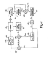
- a Fuel Control Computer 10 in response to the operational parameters of an Engine 12, generates a base fuel quantity signal Q indicative of the engines fuel requirements.
- the Fuel Control Computer 10 may be of any type known in the art.
- a Fuel Delivery Device 14 such as one or more fuel injectors or an electronically controlled carburetor is activated by the Fuel Control Computer 10 to deliver a quantity of fuel to each cylinder of the Engine 12 proportional to the value of the base fuel quantity signal Q.
- a Signal Generator 16 responsive to the rotation of an output member of Engine 10 generates first signals "P i " indicative of the average engine speed between predetermined equal rotational intervals of the engines output member such as the rotational interval of the engine's crankshaft between each piston in turn being at its top dead center position prior to its power stroke.
- the first signals "P i " may be indicative of the average engine speed during the rotational interval or preferably the time or period required for the engine's crankshaft to rotate through each of the equal rotational intervals.
- the first signals P i are then averaged in Signal Averaging Circuit 18 to generate an average first signal P AVG .
- the Average Signal Generator 18 computes the average signal P AVG having a value: where N is the number of samples. N may be the number of cylinders in the engine or any other number as is known in the art.
- a Difference Circuit 20 subtracts the first signal P i from the average first signal P AVG to generate a difference signal ⁇ P i for each first signal.
- Individual Integrators 22 sum the difference signals P i to generate a plurality of preliminary correction signals q i , one for each of the engine's cylinders.
- the individual preliminary correction signals q i are then multiplied by a constant in Multiplier Circuit 24 to generate fuel quantity correction signals Q i .
- the correction signals Qi generated for each cylinder are then averaged in an Averaging Circuit 26 to generate an average correction signal Q AVG having a value where N is the number of cylinders in the engine.
- the average correction signal Q AVG is then subtracted from the base fuel quantity signal Q generated by the Fuel Control Computer 10, in a Subtraction Circuit 28 to generate an intermediate fuel quantity signal having the value Q- Q AVG .
- the correction signal Q i is then added to the intermediate fuel quantity signal in Adder Circuit 30 to generate a corrected fuel quantity signal Q-QAVG + Q i for the "i"th engine cylinder.
- the Fuel Delivery Device 14 responds to the corrected fuel quantity signal to deliver a quantity of fuel to the "i"th cylinder tending to equalize the duration of the first signals P i generated by each of the engine's cylinders. It is further recognized that in volumetric fuel delivery devices where the injection is controlled as a function of output member's angle, further modification of the corrected fuel quantity signal as a function of engine speed will be required. Those skilled in the art will recognize that when the first signals P i become equal, the torque contribution of each cylinder to the total output torque are likewise equal.
- the redistribution control does not add or subtract from the basic calibration of the fuel control system, but only redistributes the fuel among the individual cylinders in a way tending to equalize the torque contribution of each cylinder to the total output torque of the engine. This redistribution control results in a smoother and more efficient operation of the engine and also is capable of compensating for mechanical and/or geometrical differences which otherwise would cause the torque contributions of the individual cylinders to differ.
- Subtraction Circuit 20 may be arranged to generate a difference signal ⁇ P i having a value P i -P AVG .
- the corrected fuel quantity signal will have a value equal to Q + Q AVG - Q il
- Subtraction Circuit 28 will become an Adder adding Q AVG to Q and Adder 30 will become a Subtraction Circuit subtracting Q i from the sum Q + Q AVG . The result will be the same.
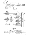
- FIGURE 2 The details of the Signal Generator 18 are shown in FIGURE 2.
- the Signal Generator 18 will be discussed with reference to a 4 cylinder engine, but its principles are equally applicable to all multiple cylinder engines.
- a magnetic pick-up 34 detects the passing of the teeth on a rotating wheel 32 attached a rotating output member of the engine, such as the engine's crankshaft and generates a signal which is amplified by amplifier 36.
- the rotating wheel 32 has two teeth displaced at 180° intervals such that magnetic pick-up 34 produces 4 output signals, one for each cylinder, during each operational cycle of the engine, i.e. two revolutions of the engines crankshaft.
- the two teeth on wheel 32 may be positioned such that one of them is adjacent to the magnetic pick-up 34 each time a piston in one of the cylinders is at its top-dead-center position. Any other rotational position of the crankshaft may be used if desired.
- Amplifier 36 amplifies the output signal of magnetic pick-up 34 and generates a rotational position signal " ⁇ p" at precisely 180° rotational intervals of the engines crankshaft.
- a Period Counter 38 counts the pulses generated by a Clock 40 between successive rotational position signals ⁇ p .
- the content of the Period Counter 38 is a number indicative of the time required by the crankshaft to rotate through the 180° interval. As is known in the art this number is inversely proportional to the average engine speed during this same rotational interval and is said first signal "P i ".
- Period Counter 38 At the end of each 180° rotational interval, indicated by the occurrence of a rotational position signal 6, the content of the Period Counter 38 is transferred to a Period Register 42 where it is temporarily stored. This clears Period Counter 38 and Period Counter 38 begins to count clock pulses again to generate a number indicative of the time required by the crankshaft to rotate through the next 180° rotational interval.
- Period Register 42 is subsequently transferred to the Signal Averaging Circuit 18 where it is averaged with the content of Period Register 42 for the preceding 180° rotational intervals to generate the signal P AVG indicative of the average time it took the cranksahft to rotate through each 180° interval during a complete operational cycle of the engine.
- the Signal Averaging Circuit 18 may compute the average first signal in accordance with the equation: or may generate an equivalent average signal as taught in U.S. Patent No. 4,197,767 for computing the average phase angle.
- the details of the Individual Integrators 22 are shown on FIGURE 3.
- the difference signals ⁇ P i from the subtraction circuit 20 are received by a Limiter 44 which limits the absolute value of the difference signal ⁇ P i to a maximum value to prevent start-up, an occasional misfire or similar events from excessively distorting the value of the generated preliminary correction signals q i .
- the limited value of the difference signal A P i is applied to a plurality of Accumulators 46 through 52. Since in the given example, the fuel redistribution control is for a four (4) cylinder engine, there are four Accumulators, one for each cylinder.
- a Counter 54 receives the position signals ⁇ p generated at the beginning of each torque impulse to be analyzed.
- the Counter 54 also receives a cylinder reference signal (REF) which is indicative of the beginning of the torque impulse for a predetermined one of the four cylinders.
- the cylinder reference signal REF resets the Counter 54 at the beginning of each engine cycle.
- the Counter 54 then counts the position signals ⁇ p and generates a number indicative of the cylinder whose torque impulse is being analyzed.
- the current number in Counter 54 is received by a Decoder 56 which generates a signal enabling one of the Accumulators 46 through 52, corresponding to the number in Counter 54, to receive and store the limited difference signal ⁇ P i .
- the Accumulators 46 through 52 are thus activated one at a time in a predetermined sequence to receive and store the difference signals ⁇ P i .
- the accumulated difference signals ⁇ P i in each of the Accumulators is the preliminary correction signal q i for its associated cylinder.
- Decoder 56 The outputs of Decoder 56 are also applied to a Swtich 58 which transmits the preliminary correction signal q i to the Muliplier 24 where it is multiplied by a constant to generate the correction signal Q i .
- the sequence in which the Switch 58 connects the outputs of the individual Accumulators 46 through 52 to Multiplier 24 is selected so that the preliminary correction signals q i transmitted to Multiplier 24 is the preliminary correction signal for the engine cylinder whose fuel quantity Q is currently being computed.
- FIGURE 4 The details of the Accumulators 46 through 52 are shown in FIGURE 4. Since all of the Accumulators are identical, only Accumulator 46 will be explained in detail.
- the output of Limiter 44 and one of the outputs of Decoder 56 are received at alternate inputs to AND Gate 60.
- the output of AND Gate 60 is connected to one input of Adder 62 having its output connected to Shift Register 64.
- the output of Shift Register 64 is connected to Switch 58 and to the other input to Adder 62. Therefore, each time a difference signal is generated for a particular cylinder, the AND Gate 60 in the corresponding Accumulator is enabled by the output of Decoder 56 and the difference signal A P i is added to the content of Shift Register 64.
Landscapes
- Engineering & Computer Science (AREA)
- Chemical & Material Sciences (AREA)
- Combustion & Propulsion (AREA)
- Mechanical Engineering (AREA)
- General Engineering & Computer Science (AREA)
- Electrical Control Of Air Or Fuel Supplied To Internal-Combustion Engine (AREA)
- Combined Controls Of Internal Combustion Engines (AREA)
- Fuel-Injection Apparatus (AREA)
- Combustion Methods Of Internal-Combustion Engines (AREA)
Priority Applications (1)
| Application Number | Priority Date | Filing Date | Title |
|---|---|---|---|
| AT84400309T ATE38081T1 (de) | 1983-02-22 | 1984-02-15 | Brennstoffverteilungssteuerung fuer brennkraftmaschinen. |
Applications Claiming Priority (2)
| Application Number | Priority Date | Filing Date | Title |
|---|---|---|---|
| US06/468,817 US4535406A (en) | 1983-02-22 | 1983-02-22 | Fuel distribution control for an internal combustion engine |
| US468817 | 1983-02-22 |
Publications (3)
| Publication Number | Publication Date |
|---|---|
| EP0120730A2 true EP0120730A2 (fr) | 1984-10-03 |
| EP0120730A3 EP0120730A3 (en) | 1985-10-23 |
| EP0120730B1 EP0120730B1 (fr) | 1988-10-19 |
Family
ID=23861361
Family Applications (1)
| Application Number | Title | Priority Date | Filing Date |
|---|---|---|---|
| EP84400309A Expired EP0120730B1 (fr) | 1983-02-22 | 1984-02-15 | Commande de répartition de carburant pour moteur à combustion interne |
Country Status (7)
| Country | Link |
|---|---|
| US (1) | US4535406A (fr) |
| EP (1) | EP0120730B1 (fr) |
| JP (1) | JPS59160044A (fr) |
| AT (1) | ATE38081T1 (fr) |
| CA (1) | CA1220264A (fr) |
| DE (1) | DE3474708D1 (fr) |
| ES (1) | ES529918A0 (fr) |
Cited By (7)
| Publication number | Priority date | Publication date | Assignee | Title |
|---|---|---|---|---|
| DE3609245A1 (de) * | 1985-03-19 | 1986-10-02 | Diesel Kiki Co | Vorrichtung zum regeln der leerlaufdrehgeschwindigkeit einer brennkraftmaschine |
| DE3624773A1 (de) * | 1985-07-23 | 1987-02-05 | Lucas Ind Plc | Verfahren zum betreiben eines verbrennungsmotors und einstell-regelsystem fuer einen verbrennungsmotor |
| DE3644639A1 (de) * | 1985-12-28 | 1987-07-02 | Diesel Kiki Co | Einrichtung zum steuern des leerlaufbetriebs eines verbrennungsmotors |
| US4843556A (en) * | 1985-07-23 | 1989-06-27 | Lucas Industries Public Limited Company | Method and apparatus for controlling an internal combustion engine |
| US5001645A (en) * | 1987-01-14 | 1991-03-19 | Lucas Industries Public Limited Company | Adaptive control system for an engine |
| EP0448603A4 (en) * | 1988-12-19 | 1993-01-13 | Motorola, Inc. | System for monitoring and controlling engine performance |
| EP1065363A1 (fr) * | 1999-07-02 | 2001-01-03 | Renault | Procédé de contrôle du couple d'un moteur à combustion interne |
Families Citing this family (17)
| Publication number | Priority date | Publication date | Assignee | Title |
|---|---|---|---|---|
| US4616617A (en) * | 1984-04-07 | 1986-10-14 | Volkswagenwerk Aktiengesellschaft | Method and arrangement for combustion chamber identification in an internal combustion engine |
| JPH0650077B2 (ja) * | 1984-08-10 | 1994-06-29 | 日本電装株式会社 | 内燃機関用燃料噴射量制御方法 |
| GB2165065B (en) * | 1984-09-22 | 1988-02-10 | Diesel Kiki Co | Idling control of ic engines |
| US5157613A (en) * | 1987-01-14 | 1992-10-20 | Lucas Industries Public Limited Company | Adaptive control system for an engine |
| GB8715130D0 (en) * | 1987-06-27 | 1987-08-05 | Lucas Ind Plc | Adaptive control system for i c engine |
| GB8721688D0 (en) * | 1987-09-15 | 1987-10-21 | Lucas Ind Plc | Adaptive control system |
| DE4414727B4 (de) * | 1993-04-27 | 2004-01-29 | Hitachi, Ltd. | Steuerverfahren und Steuereinheit für Mehrzylinder-Brennkraftmaschinen |
| DE4447846B4 (de) * | 1993-04-27 | 2006-06-14 | Hitachi, Ltd. | Verfahren und Vorrichtung zum Steuern einer Brennkraftmaschine |
| US5445128A (en) * | 1993-08-27 | 1995-08-29 | Detroit Diesel Corporation | Method for engine control |
| EP0763725A3 (fr) * | 1995-09-14 | 1999-07-21 | MTU Motoren- und Turbinen-Union Friedrichshafen GmbH | Procédé de détermination des différences entre les couples non-uniformes de cylindres dans un moteur à combustion à combustion interne et application du procédé |
| DE19538369A1 (de) * | 1995-10-14 | 1997-04-17 | Bosch Gmbh Robert | Verfahren und Anordnung zum Reduzieren von Lastwechselschlägen bei einem Kraftfahrzeug |
| JPH09195826A (ja) * | 1996-01-12 | 1997-07-29 | Yamaha Motor Co Ltd | 多気筒エンジンの空燃比制御方法 |
| US5669354A (en) * | 1996-04-18 | 1997-09-23 | General Motors Corporation | Active driveline damping |
| DE19816641C1 (de) | 1998-04-15 | 1999-10-07 | Daimler Chrysler Ag | Verfahren zur Bestimmung der Laufruhe eines Ottomotors |
| DE19845749A1 (de) * | 1998-10-05 | 2000-04-06 | Bayerische Motoren Werke Ag | Verfahren zur Kompensation des Einflusses unterschiedlicher Leckluftmengen |
| DE19859074A1 (de) * | 1998-12-21 | 2000-06-29 | Bosch Gmbh Robert | Verfahren zur Regelung der Laufruhe eines Verbrennungsmotors |
| JP4424380B2 (ja) * | 2007-06-20 | 2010-03-03 | 株式会社デンソー | 噴射量制御装置およびそれを用いた燃料噴射システム |
Family Cites Families (11)
| Publication number | Priority date | Publication date | Assignee | Title |
|---|---|---|---|---|
| DE2507057A1 (de) * | 1975-02-19 | 1976-09-02 | Bosch Gmbh Robert | Verfahren und vorrichtung zur bestimmung der laufunruhe einer brennkraftmaschine |
| DE2507138C2 (de) * | 1975-02-19 | 1984-08-23 | Robert Bosch Gmbh, 7000 Stuttgart | Verfahren und Vorrichtung zur Gewinnung einer die Annäherung an eine vorgegebene Magerlaufgrenze angebenden Meßgröße beim Betrieb einer Brennkraftmaschine |
| DE2507137A1 (de) * | 1975-02-19 | 1976-09-02 | Bosch Gmbh Robert | Verfahren und vorrichtung zur regelung des betriebsverhaltens einer brennkraftmaschine |
| US4197767A (en) * | 1978-05-08 | 1980-04-15 | The Bendix Corporation | Warm up control for closed loop engine roughness fuel control |
| US4357662A (en) * | 1978-05-08 | 1982-11-02 | The Bendix Corporation | Closed loop timing and fuel distribution controls |
| DE2906782A1 (de) * | 1979-02-22 | 1980-09-04 | Bosch Gmbh Robert | Einrichtung zum daempfen von ruckelschwingungen bei einer brennkraftmaschine |
| US4344140A (en) * | 1980-09-15 | 1982-08-10 | The Bendix Corporation | Closed loop engine roughness control |
| US4418669A (en) * | 1982-07-19 | 1983-12-06 | The Bendix Corporation | Fuel distribution control system for an internal combustion engine |
| US4475511A (en) * | 1982-09-01 | 1984-10-09 | The Bendix Corporation | Fuel distribution control system for an internal combustion engine |
| US4476833A (en) * | 1982-10-21 | 1984-10-16 | The Bendix Corporation | Phase angle modification of the torque amplitude for fuel distribution control systems |
| US4539956A (en) * | 1982-12-09 | 1985-09-10 | General Motors Corporation | Diesel fuel injection pump with adaptive torque balance control |
-
1983
- 1983-02-22 US US06/468,817 patent/US4535406A/en not_active Expired - Lifetime
- 1983-11-10 CA CA000440956A patent/CA1220264A/fr not_active Expired
-
1984
- 1984-02-15 AT AT84400309T patent/ATE38081T1/de active
- 1984-02-15 EP EP84400309A patent/EP0120730B1/fr not_active Expired
- 1984-02-15 DE DE8484400309T patent/DE3474708D1/de not_active Expired
- 1984-02-21 ES ES529918A patent/ES529918A0/es active Granted
- 1984-02-22 JP JP59030471A patent/JPS59160044A/ja active Pending
Cited By (9)
| Publication number | Priority date | Publication date | Assignee | Title |
|---|---|---|---|---|
| DE3609245A1 (de) * | 1985-03-19 | 1986-10-02 | Diesel Kiki Co | Vorrichtung zum regeln der leerlaufdrehgeschwindigkeit einer brennkraftmaschine |
| DE3624773A1 (de) * | 1985-07-23 | 1987-02-05 | Lucas Ind Plc | Verfahren zum betreiben eines verbrennungsmotors und einstell-regelsystem fuer einen verbrennungsmotor |
| US4843556A (en) * | 1985-07-23 | 1989-06-27 | Lucas Industries Public Limited Company | Method and apparatus for controlling an internal combustion engine |
| US4899282A (en) * | 1985-07-23 | 1990-02-06 | Lucas Industries Public Limited Company | Method and apparatus for controlling an internal combustion engine |
| DE3644639A1 (de) * | 1985-12-28 | 1987-07-02 | Diesel Kiki Co | Einrichtung zum steuern des leerlaufbetriebs eines verbrennungsmotors |
| US5001645A (en) * | 1987-01-14 | 1991-03-19 | Lucas Industries Public Limited Company | Adaptive control system for an engine |
| EP0448603A4 (en) * | 1988-12-19 | 1993-01-13 | Motorola, Inc. | System for monitoring and controlling engine performance |
| EP1065363A1 (fr) * | 1999-07-02 | 2001-01-03 | Renault | Procédé de contrôle du couple d'un moteur à combustion interne |
| FR2795819A1 (fr) * | 1999-07-02 | 2001-01-05 | Renault | Procede de controle du couple d'un moteur a combustion interne |
Also Published As
| Publication number | Publication date |
|---|---|
| US4535406A (en) | 1985-08-13 |
| ES8503076A1 (es) | 1985-02-01 |
| EP0120730B1 (fr) | 1988-10-19 |
| EP0120730A3 (en) | 1985-10-23 |
| DE3474708D1 (en) | 1988-11-24 |
| CA1220264A (fr) | 1987-04-07 |
| JPS59160044A (ja) | 1984-09-10 |
| ATE38081T1 (de) | 1988-11-15 |
| ES529918A0 (es) | 1985-02-01 |
Similar Documents
| Publication | Publication Date | Title |
|---|---|---|
| EP0120730A2 (fr) | Commande de répartition de carburant pour moteur à combustion interne | |
| US4688535A (en) | Apparatus for influencing control quantities of an internal combustion engine | |
| US4744243A (en) | Method of and apparatus for detecting maximum cylinder pressure angle in internal combustion engine | |
| US5699253A (en) | Nonlinear dynamic transform for correction of crankshaft acceleration having torsional oscillations | |
| EP0107523B1 (fr) | Système de commande de la distribution de carburant pour un moteur à combustion interne | |
| US4936277A (en) | System for monitoring and/or controlling multiple cylinder engine performance | |
| US4357662A (en) | Closed loop timing and fuel distribution controls | |
| US4782692A (en) | Engine crankshaft position sensor | |
| US4268910A (en) | Method for controlling timing of spark ignition for an internal combustion engine by feedback related to the detection of knocking | |
| US4715009A (en) | Device for determining angular position of a rotating part | |
| US4860222A (en) | Method and apparatus for measuring engine mass air flow | |
| US4337647A (en) | Engine roughness sensor | |
| US6328014B1 (en) | Control method | |
| US5829412A (en) | System for controlling an internal combustion engine | |
| US4240388A (en) | Method for controlling timing of spark ignition for an internal combustion engine | |
| US5305220A (en) | Apparatus for electronically measuring the speed of internal combustion engines and method of operating such apparatus in monitoring an internal combustion engine | |
| JP2550397B2 (ja) | 機関制御用信号発生装置 | |
| US4635201A (en) | Apparatus for detecting amount of change in rotational speed of internal combustion engine | |
| US4653315A (en) | Engine top dead center locating method | |
| US6363318B1 (en) | Method to compensate errors in engine speed measurement | |
| EP0398909A1 (fr) | Appareil de determination de la vitesse, de la position angulaire et du sens de rotation d'un arbre rotatif. | |
| US4520449A (en) | Phase angle detector | |
| EP0721107A2 (fr) | Méthode pour déterminer la vitesse de rotation d'un moteur à combustion interne | |
| JP2763294B2 (ja) | 内燃機関用制御器の入力信号検出装置 | |
| EP0162470A2 (fr) | Méthode de commande de l'alimentation en carburant d'un moteur à combustion interne |
Legal Events
| Date | Code | Title | Description |
|---|---|---|---|
| PUAI | Public reference made under article 153(3) epc to a published international application that has entered the european phase |
Free format text: ORIGINAL CODE: 0009012 |
|
| AK | Designated contracting states |
Designated state(s): AT DE FR GB IT |
|
| PUAL | Search report despatched |
Free format text: ORIGINAL CODE: 0009013 |
|
| RHK1 | Main classification (correction) |
Ipc: F02D 41/34 |
|
| AK | Designated contracting states |
Designated state(s): AT DE FR GB IT |
|
| 17P | Request for examination filed |
Effective date: 19860312 |
|
| 17Q | First examination report despatched |
Effective date: 19870224 |
|
| RAP1 | Party data changed (applicant data changed or rights of an application transferred) |
Owner name: ALLIED CORPORATION |
|
| RAP1 | Party data changed (applicant data changed or rights of an application transferred) |
Owner name: ALLIED-SIGNAL INC. |
|
| GRAA | (expected) grant |
Free format text: ORIGINAL CODE: 0009210 |
|
| AK | Designated contracting states |
Kind code of ref document: B1 Designated state(s): AT DE FR GB IT |
|
| REF | Corresponds to: |
Ref document number: 38081 Country of ref document: AT Date of ref document: 19881115 Kind code of ref document: T |
|
| REF | Corresponds to: |
Ref document number: 3474708 Country of ref document: DE Date of ref document: 19881124 |
|
| ET | Fr: translation filed | ||
| ITF | It: translation for a ep patent filed | ||
| PLBI | Opposition filed |
Free format text: ORIGINAL CODE: 0009260 |
|
| 26 | Opposition filed |
Opponent name: KLOECKNER-HUMBOLDT-DEUTZ AG Effective date: 19890719 |
|
| PLBN | Opposition rejected |
Free format text: ORIGINAL CODE: 0009273 |
|
| STAA | Information on the status of an ep patent application or granted ep patent |
Free format text: STATUS: OPPOSITION REJECTED |
|
| 27O | Opposition rejected |
Effective date: 19900428 |
|
| ITTA | It: last paid annual fee | ||
| PGFP | Annual fee paid to national office [announced via postgrant information from national office to epo] |
Ref country code: GB Payment date: 19991224 Year of fee payment: 17 |
|
| PGFP | Annual fee paid to national office [announced via postgrant information from national office to epo] |
Ref country code: AT Payment date: 19991227 Year of fee payment: 17 |
|
| PGFP | Annual fee paid to national office [announced via postgrant information from national office to epo] |
Ref country code: DE Payment date: 19991229 Year of fee payment: 17 |
|
| PGFP | Annual fee paid to national office [announced via postgrant information from national office to epo] |
Ref country code: FR Payment date: 20000207 Year of fee payment: 17 |
|
| PG25 | Lapsed in a contracting state [announced via postgrant information from national office to epo] |
Ref country code: GB Free format text: LAPSE BECAUSE OF NON-PAYMENT OF DUE FEES Effective date: 20010215 Ref country code: AT Free format text: LAPSE BECAUSE OF NON-PAYMENT OF DUE FEES Effective date: 20010215 |
|
| PG25 | Lapsed in a contracting state [announced via postgrant information from national office to epo] |
Ref country code: DE Free format text: LAPSE BECAUSE OF NON-PAYMENT OF DUE FEES Effective date: 20010228 |
|
| GBPC | Gb: european patent ceased through non-payment of renewal fee |
Effective date: 20010215 |
|
| PG25 | Lapsed in a contracting state [announced via postgrant information from national office to epo] |
Ref country code: FR Free format text: LAPSE BECAUSE OF NON-PAYMENT OF DUE FEES Effective date: 20011031 |
|
| REG | Reference to a national code |
Ref country code: FR Ref legal event code: ST |