EP0120740A1 - Skibremse - Google Patents
Skibremse Download PDFInfo
- Publication number
- EP0120740A1 EP0120740A1 EP84400363A EP84400363A EP0120740A1 EP 0120740 A1 EP0120740 A1 EP 0120740A1 EP 84400363 A EP84400363 A EP 84400363A EP 84400363 A EP84400363 A EP 84400363A EP 0120740 A1 EP0120740 A1 EP 0120740A1
- Authority
- EP
- European Patent Office
- Prior art keywords
- ski
- arms
- brake
- braking
- pedal
- Prior art date
- Legal status (The legal status is an assumption and is not a legal conclusion. Google has not performed a legal analysis and makes no representation as to the accuracy of the status listed.)
- Granted
Links
- 239000000872 buffer Substances 0.000 claims description 5
- 230000010355 oscillation Effects 0.000 description 2
- 240000008042 Zea mays Species 0.000 description 1
- 238000005452 bending Methods 0.000 description 1
- 239000000470 constituent Substances 0.000 description 1
- 230000014759 maintenance of location Effects 0.000 description 1
- 239000002184 metal Substances 0.000 description 1
- 230000004048 modification Effects 0.000 description 1
- 238000012986 modification Methods 0.000 description 1
- 239000000843 powder Substances 0.000 description 1
- 230000000717 retained effect Effects 0.000 description 1
- 238000000926 separation method Methods 0.000 description 1
Images


Classifications
-
- A—HUMAN NECESSITIES
- A63—SPORTS; GAMES; AMUSEMENTS
- A63C—SKATES; SKIS; ROLLER SKATES; DESIGN OR LAYOUT OF COURTS, RINKS OR THE LIKE
- A63C7/00—Devices preventing skis from slipping back; Ski-stoppers or ski-brakes
- A63C7/10—Hinged stoppage blades attachable to the skis in such manner that these blades can be moved out of the operative position
- A63C7/1006—Ski-stoppers
- A63C7/1013—Ski-stoppers actuated by the boot
- A63C7/102—Ski-stoppers actuated by the boot articulated about one transverse axis
- A63C7/1026—Ski-stoppers actuated by the boot articulated about one transverse axis laterally retractable above the ski surface
Definitions
- the present invention relates to a ski brake of the type in which two movable braking arms are provided, arranged on either side of the ski equipped with such a brake, and the ends of which are opposite the active ends, carry a control pedal capable of being actuated by the skier's shoe.
- the invention relates to ski brakes of this kind, the arrangement is such that the extremities "active sides of the two movable braking arms are retracted above the ski when the latter are raised in retracted position .
- ski brakes thus designed so as to prevent the active ends of the braking arms from overhanging with respect to the side edges of the ski in their lifting position.
- FIG. 7 of French patent 2,055,424 describes a ski brake in which the brake arms are retracted into the retracted position by pivoting about a longitudinal axis.
- French patent application 2,447,208 also describes a brake, the braking arms of which are retracted in the retracted position. This retraction is obtained by a pivoting movement of the braking arms ensuring a lifting of their active ends above ski.
- this has the drawback of involving a large size of this brake in the height direction.
- French patent applications 2,451,754 and 2,452,300 relate to ski brakes in which the retraction of the brake pads is obtained in a way by. an oscillating movement of the two corresponding arms in the transverse direction thanks to a movement of these inside the bearings in which their bent parts are articulated serving as pivot axes. This oscillation movement is then controlled by the relative pivoting which occurs between the control pedal and the corresponding ends of the brake arms at the end of the lifting movement of the latter.
- the present invention aims to achieve a ski brake of the same general type, but which is designed so as to avoid the drawbacks mentioned above.
- the design of this brake is therefore such that it is particularly simple and inexpensive.
- This design is also such that the retraction of this brake can be carried out without significant efforts and that it is possible to provide a return spring of limited power.
- the brake arms of the ski brake according to the invention are exclusively carried by the control pedal, which is articulated on the ski around a transverse axis, and their corresponding ends are bent to form a V having its point directed on the side opposite to the skates and / or on the side opposite to the ski and are mounted journalling in bores, of the same angular orientation, formed in the pedal, however means are provided tending to rotate on themselves the braking arm in these bores, after their raising, so that their active ends are retracted above the ski.
- the means provided for controlling the rotation of the braking arms on themselves in their retracted position are constituted by elastic members constantly tending to cause such rotation, ci being prevented from occurring until the braking arms have not been raised above the upper surface of the ski.
- the rotation of the braking arms in their retracted position is caused by a stop disposed above the position for raising the active ends of these arms.
- this stop prevents these ends from continuing their lifting movement when the control pedal is folded against the ski, which forces the braking arms to turn on themselves in the bores provided inside this pedal.
- the stop thus provided may be constituted by another element of corresponding ski equipment, for example by the rotary plate of a pivoting heel piece for fixing.
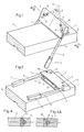
- the ski brake shown in FIGS. 1 to 7 comprises two movable arms 1, made of rigid metal wire, which are intended to be arranged on one and the other sides of the corresponding ski S. Contrary to what is the case in the most ski brakes of this kind, these two arms do not articulate directly on the ski. In fact, they are exclusively carried by a control pedal 2 capable of being actuated by the corresponding shoe of the skier. This pedal is articulated around an axis 3 which extends in the transverse direction above the ski and parallel to the upper surface thereof, this axis being carried by a plate 4 fixed on the top of the ski.
- the two brake arms 1 are mounted on the control pedal 2 via one of their ends, in this case their end 5 which is opposite to the active end 6 on which a brake shoe is provided. 7.
- the ends 5 of the two braking arms 1 are bent towards each other and mounted to rotate on themselves inside bores 8 formed in the thickness of the control pedal 2 and which have the same angular orientation . These ends are retained in place by a pin 9, or any other suitable member, allowing them to rotate on themselves.
- the plane formed by the bent ends 5 of the two braking arms is parallel to the upper and lower faces of the pedal 2. Given their inclination relative to each other, the bent ends 5 of the two braking arms 1 form a V whose apex 0 is directed on the side opposite the active ends 6 of these two arms (see FIG. 7). Of course this summit is also located in the plane perpendicular to the ski which passes through the median longitudinal axis XY thereof.
- the bending angle braking arms and the angular orientation of the bores 8 provided in the thickness of the pedal 2 are such that the spacing of the ends of the braking pads can be modified, by simple rotation of the arms 1 on themselves at inside the bores 8, between a maximum spacing L1 corresponding to the working position of these two arms and a minimum spacing position L2 corresponding to the lifting position of these above the ski, when the brake is on standby Operating.
- This minimum spacing L2 is such that the braking arms, and in particular their ends 6, are retracted with respect to the lateral sides of the ski. so as not to overflow with respect to them (see Figure 7).
- elastic return members which tend to rotate on themselves, the bent ends 5 of the braking arms inside the bores 8, in their position corresponding to the minimum spacing L2 of the active ends of these same arms.
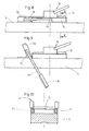
- These elastic members may consist of cylindrical rubber pads 10, housed in the thickness of the pedal 2, and each acting against a flat 11 provided on the bent end 5 of the corresponding braking arm.
- the angular orientation of this flat is such that it is disposed tangentially to a generator of the corresponding elastic buffer 10 when the respective braking arm 1 is in its retracted position (see FIG. 4).
- the flat 11 may include the position shown in FIG. 4a. In this case the elasticity of the elastic pad tends to return the corresponding arm to its retracted position.
- this spring may consist of a torsion spring 12 disposed around the hinge pin 3 of this pedal.
- the spacing and approximation movements of the braking arms are due to the bent shape of their control ends 5 and to the angular orientation of the bores 8, formed inside the pedal 2, to serve as rotation bearings at the corresponding ends of these two arms.
- these movements are carried out without significant friction against the braking arms against the ski or / of ancillary parts fixed on the latter. Therefore, a return spring 12 of relatively low power is sufficient to control the movement of these arms in their active working position.
- the boot in the waiting position, the boot is not made to undergo a significant vertical thrust liable to disturb the triggering of the safety binding ensuring the retention of this boot on the ski.
- Yet another advantage of the brake according to the invention consists in that it has an extremely small size in the height direction. This makes it possible to arrange it without disadvantage below the location of the central part of the corresponding shoe.
- Figures 8 to 10 show a variant of the embodiment described above. This differs from it only in that the elastic return members of the brake arms, in their retracted position, are eliminated and that the corresponding movement is then controlled by a stop positioned above the lifting position. brake pads. As provided in the example shown, this stop may advantageously be constituted by another element of the corresponding ski equipment, in this case the turntable 13 of a heel piece of attachment 14.
- FIGS. 11 to 13 show another embodiment of the ski brake according to the invention. This differs from that shown in FIGS. 1 to 7 by a different orientation of the bores made in the thickness of the control pedal and which serve as rotation bearings at the corresponding bent ends of the braking arms.
- the plane formed by the bent ends 5b of the braking arms 1b, is perpendicular to the upper and lower faces of the control pedal 2b. Furthermore, the top 0 of the V, formed by the axes of these two bent ends, is directed upwards, and no longer on the side opposite to the brake pads (see FIG. 12).
- the arrangement is such that in the raising position of the braking arms 1b, corresponding to the folding of the control pedal 2b against the ski, the braking pads 7b have a minimum spacing whereby they are then retracted from on the lateral sides of the ski (see figure 11 ) .
- the raising of the control pedal is accompanied by a spacing of the pads of braking 7b on either side of the ski by rotation of these arms in the corresponding bores.
- the return of the braking arms to their retraction position, shown in FIG. 11, can be ensured either by elastic members, such as the cylindrical buffers 10 provided in the embodiment of FIGS. 1 to 7 , or by a stop limiting the raising of the brake shoes, as provided in the variant according to FIGS. 8 to 10.
- the brake according to the invention is not limited to the examples which have been described above for information only. So the plan formed by the bent ends of the brake arms could be inclined relative to the upper and lower faces of the control pedal instead of being parallel or perpendicular thereto, the top of the V formed by the axes of these ends would then be directed to the times on the side opposite to the brake pads and upwards, that is to say on the side opposite to the ski.
Landscapes
- Braking Arrangements (AREA)
Priority Applications (1)
| Application Number | Priority Date | Filing Date | Title |
|---|---|---|---|
| AT84400363T ATE21040T1 (de) | 1983-03-17 | 1984-02-23 | Skibremse. |
Applications Claiming Priority (2)
| Application Number | Priority Date | Filing Date | Title |
|---|---|---|---|
| FR8304362 | 1983-03-17 | ||
| FR8304362A FR2542624B1 (fr) | 1983-03-17 | 1983-03-17 | Frein a ski |
Publications (2)
| Publication Number | Publication Date |
|---|---|
| EP0120740A1 true EP0120740A1 (de) | 1984-10-03 |
| EP0120740B1 EP0120740B1 (de) | 1986-07-30 |
Family
ID=9286957
Family Applications (1)
| Application Number | Title | Priority Date | Filing Date |
|---|---|---|---|
| EP84400363A Expired EP0120740B1 (de) | 1983-03-17 | 1984-02-23 | Skibremse |
Country Status (6)
| Country | Link |
|---|---|
| US (1) | US4573700A (de) |
| EP (1) | EP0120740B1 (de) |
| JP (1) | JPS59214472A (de) |
| AT (1) | ATE21040T1 (de) |
| DE (1) | DE3460371D1 (de) |
| FR (1) | FR2542624B1 (de) |
Families Citing this family (4)
| Publication number | Priority date | Publication date | Assignee | Title |
|---|---|---|---|---|
| FR2631555B1 (fr) * | 1988-05-18 | 1990-08-17 | Salomon Sa | Frein de ski |
| US6092828A (en) * | 1998-08-13 | 2000-07-25 | Schumacher; David | Snow ski traction device and method |
| US20050062240A1 (en) * | 2003-09-19 | 2005-03-24 | Kerchival Holt | Snowboard control device |
| DE102019108350A1 (de) * | 2019-03-29 | 2020-10-01 | Marker Deutschland Gmbh | Bremsvorrichtung |
Citations (5)
| Publication number | Priority date | Publication date | Assignee | Title |
|---|---|---|---|---|
| FR2055424A5 (de) * | 1969-07-22 | 1971-05-07 | Schwarz Gunter | |
| FR2339415A1 (fr) * | 1976-01-28 | 1977-08-26 | Tmc Corp | Dispositif d'arret pour ski |
| FR2357271A1 (fr) * | 1974-03-15 | 1978-02-03 | Salomon & Fils F | Dispositif pour le freinage d'un ski apres degagement de la chaussure de ski |
| FR2451754A1 (fr) * | 1979-03-20 | 1980-10-17 | Look Sa | Frein a ski |
| FR2498936A1 (fr) * | 1981-01-30 | 1982-08-06 | Tmc Corp | Frein de ski |
Family Cites Families (5)
| Publication number | Priority date | Publication date | Assignee | Title |
|---|---|---|---|---|
| FR2305206A1 (fr) * | 1975-03-25 | 1976-10-22 | Salomon & Fils F | Frein de ski |
| AT366277B (de) * | 1978-09-19 | 1982-03-25 | Tyrolia Freizeitgeraete | Skibremse |
| AT366280B (de) * | 1979-11-16 | 1982-03-25 | Tyrolia Freizeitgeraete | Skibremse |
| FR2483792A1 (fr) * | 1980-06-10 | 1981-12-11 | Look Sa | Frein a ski |
| IT1141880B (it) * | 1980-07-23 | 1986-10-08 | Ettore Bortoli | Freno per sci a bracci rientranti con comando a piani inclinati |
-
1983
- 1983-03-17 FR FR8304362A patent/FR2542624B1/fr not_active Expired
-
1984
- 1984-02-23 EP EP84400363A patent/EP0120740B1/de not_active Expired
- 1984-02-23 DE DE8484400363T patent/DE3460371D1/de not_active Expired
- 1984-02-23 AT AT84400363T patent/ATE21040T1/de not_active IP Right Cessation
- 1984-02-28 US US06/584,391 patent/US4573700A/en not_active Expired - Fee Related
- 1984-03-17 JP JP59052062A patent/JPS59214472A/ja active Pending
Patent Citations (5)
| Publication number | Priority date | Publication date | Assignee | Title |
|---|---|---|---|---|
| FR2055424A5 (de) * | 1969-07-22 | 1971-05-07 | Schwarz Gunter | |
| FR2357271A1 (fr) * | 1974-03-15 | 1978-02-03 | Salomon & Fils F | Dispositif pour le freinage d'un ski apres degagement de la chaussure de ski |
| FR2339415A1 (fr) * | 1976-01-28 | 1977-08-26 | Tmc Corp | Dispositif d'arret pour ski |
| FR2451754A1 (fr) * | 1979-03-20 | 1980-10-17 | Look Sa | Frein a ski |
| FR2498936A1 (fr) * | 1981-01-30 | 1982-08-06 | Tmc Corp | Frein de ski |
Also Published As
| Publication number | Publication date |
|---|---|
| ATE21040T1 (de) | 1986-08-15 |
| FR2542624A1 (fr) | 1984-09-21 |
| JPS59214472A (ja) | 1984-12-04 |
| EP0120740B1 (de) | 1986-07-30 |
| FR2542624B1 (fr) | 1985-06-28 |
| DE3460371D1 (en) | 1986-09-04 |
| US4573700A (en) | 1986-03-04 |
Similar Documents
| Publication | Publication Date | Title |
|---|---|---|
| WO2004073811A1 (fr) | Fixation pour maintenir une chaussure solidairement d’une planche des neiges | |
| FR2638974A1 (fr) | Fixation de ski de fond de type charniere | |
| EP0241360B1 (de) | Sicherheitsskibindung | |
| EP0120740B1 (de) | Skibremse | |
| CH673229A5 (de) | ||
| FR2512682A1 (fr) | Frein pour ski | |
| WO1980001988A1 (fr) | Frein retractable | |
| FR2511258A1 (fr) | Talonniere pour fixation de ski de securite | |
| EP0159203B1 (de) | Fersenbacke für Skibindung mit Drehplatte | |
| CH616853A5 (de) | ||
| FR2596287A2 (fr) | Frein a ski | |
| FR2500313A1 (fr) | Dispositif de retenue de talon combine a un frein de ski | |
| CH642269A5 (fr) | Frein a ski. | |
| EP0025046B1 (de) | Einziehbare skibremse | |
| CH660976A5 (fr) | Fixation de securite pour ski. | |
| EP1011823A1 (de) | Rollschuh mit verstärkungsbeinbügel insbesondere zum bremsen | |
| FR2544211A1 (fr) | Frein de ski | |
| EP0084753B1 (de) | Skibremse | |
| CH674711A5 (de) | ||
| CH671705A5 (de) | ||
| FR2758733A1 (fr) | Ensemble de retenue d'une chaussure sur une planche de glisse destinee a la pratique du surf sur neige | |
| FR2555907A2 (fr) | Fixation de securite pour ski | |
| CH673951A5 (de) | ||
| FR2665370A1 (fr) | Frein de ski. | |
| EP0672437B1 (de) | Vorrichtung zum Veränderen der natürlichen Druckverteilung eines Skis aus Schnee |
Legal Events
| Date | Code | Title | Description |
|---|---|---|---|
| PUAI | Public reference made under article 153(3) epc to a published international application that has entered the european phase |
Free format text: ORIGINAL CODE: 0009012 |
|
| AK | Designated contracting states |
Designated state(s): AT CH DE IT LI |
|
| 17P | Request for examination filed |
Effective date: 19840919 |
|
| GRAA | (expected) grant |
Free format text: ORIGINAL CODE: 0009210 |
|
| ITF | It: translation for a ep patent filed | ||
| AK | Designated contracting states |
Kind code of ref document: B1 Designated state(s): AT CH DE IT LI |
|
| REF | Corresponds to: |
Ref document number: 21040 Country of ref document: AT Date of ref document: 19860815 Kind code of ref document: T |
|
| REF | Corresponds to: |
Ref document number: 3460371 Country of ref document: DE Date of ref document: 19860904 |
|
| PLBE | No opposition filed within time limit |
Free format text: ORIGINAL CODE: 0009261 |
|
| STAA | Information on the status of an ep patent application or granted ep patent |
Free format text: STATUS: NO OPPOSITION FILED WITHIN TIME LIMIT |
|
| 26N | No opposition filed | ||
| ITTA | It: last paid annual fee | ||
| PGFP | Annual fee paid to national office [announced via postgrant information from national office to epo] |
Ref country code: AT Payment date: 19930225 Year of fee payment: 10 |
|
| PGFP | Annual fee paid to national office [announced via postgrant information from national office to epo] |
Ref country code: DE Payment date: 19930429 Year of fee payment: 10 |
|
| PGFP | Annual fee paid to national office [announced via postgrant information from national office to epo] |
Ref country code: CH Payment date: 19930524 Year of fee payment: 10 |
|
| PG25 | Lapsed in a contracting state [announced via postgrant information from national office to epo] |
Ref country code: AT Effective date: 19940223 |
|
| PG25 | Lapsed in a contracting state [announced via postgrant information from national office to epo] |
Ref country code: LI Effective date: 19940228 Ref country code: CH Effective date: 19940228 |
|
| REG | Reference to a national code |
Ref country code: CH Ref legal event code: PL |
|
| PG25 | Lapsed in a contracting state [announced via postgrant information from national office to epo] |
Ref country code: DE Effective date: 19941101 |