EP0120852B1 - Systeme de mesure de carburant par jauge - Google Patents
Systeme de mesure de carburant par jauge Download PDFInfo
- Publication number
- EP0120852B1 EP0120852B1 EP82903517A EP82903517A EP0120852B1 EP 0120852 B1 EP0120852 B1 EP 0120852B1 EP 82903517 A EP82903517 A EP 82903517A EP 82903517 A EP82903517 A EP 82903517A EP 0120852 B1 EP0120852 B1 EP 0120852B1
- Authority
- EP
- European Patent Office
- Prior art keywords
- fuel
- signal
- dielectric constant
- capacitance
- compensator
- Prior art date
- Legal status (The legal status is an assumption and is not a legal conclusion. Google has not performed a legal analysis and makes no representation as to the accuracy of the status listed.)
- Expired
Links
- 239000000446 fuel Substances 0.000 title claims abstract description 147
- 238000012937 correction Methods 0.000 claims abstract description 47
- 239000000523 sample Substances 0.000 claims abstract description 34
- 230000004044 response Effects 0.000 claims abstract description 7
- 239000003990 capacitor Substances 0.000 claims description 43
- 230000000737 periodic effect Effects 0.000 claims description 8
- 230000001747 exhibiting effect Effects 0.000 claims description 2
- 239000002828 fuel tank Substances 0.000 abstract description 4
- 238000005259 measurement Methods 0.000 description 36
- 238000010586 diagram Methods 0.000 description 23
- 238000000034 method Methods 0.000 description 20
- 230000000694 effects Effects 0.000 description 8
- 230000006870 function Effects 0.000 description 6
- 230000001360 synchronised effect Effects 0.000 description 5
- 230000008859 change Effects 0.000 description 4
- 230000010355 oscillation Effects 0.000 description 4
- 238000012360 testing method Methods 0.000 description 4
- 238000013459 approach Methods 0.000 description 3
- 230000000007 visual effect Effects 0.000 description 3
- 239000010779 crude oil Substances 0.000 description 2
- 238000013500 data storage Methods 0.000 description 2
- 238000001514 detection method Methods 0.000 description 2
- 238000004519 manufacturing process Methods 0.000 description 2
- 230000008569 process Effects 0.000 description 2
- 238000009736 wetting Methods 0.000 description 2
- 238000004804 winding Methods 0.000 description 2
- 230000009471 action Effects 0.000 description 1
- 230000004075 alteration Effects 0.000 description 1
- 238000012512 characterization method Methods 0.000 description 1
- 239000002131 composite material Substances 0.000 description 1
- 238000011109 contamination Methods 0.000 description 1
- 230000007812 deficiency Effects 0.000 description 1
- 238000001739 density measurement Methods 0.000 description 1
- 238000013461 design Methods 0.000 description 1
- 238000004821 distillation Methods 0.000 description 1
- 230000005284 excitation Effects 0.000 description 1
- 230000006872 improvement Effects 0.000 description 1
- 230000007246 mechanism Effects 0.000 description 1
- 238000012986 modification Methods 0.000 description 1
- 230000004048 modification Effects 0.000 description 1
- 230000009467 reduction Effects 0.000 description 1
- 230000000630 rising effect Effects 0.000 description 1
Images



Classifications
-
- G—PHYSICS
- G01—MEASURING; TESTING
- G01F—MEASURING VOLUME, VOLUME FLOW, MASS FLOW OR LIQUID LEVEL; METERING BY VOLUME
- G01F23/00—Indicating or measuring liquid level or level of fluent solid material, e.g. indicating in terms of volume or indicating by means of an alarm
- G01F23/22—Indicating or measuring liquid level or level of fluent solid material, e.g. indicating in terms of volume or indicating by means of an alarm by measuring physical variables, other than linear dimensions, pressure or weight, dependent on the level to be measured, e.g. by difference of heat transfer of steam or water
- G01F23/26—Indicating or measuring liquid level or level of fluent solid material, e.g. indicating in terms of volume or indicating by means of an alarm by measuring physical variables, other than linear dimensions, pressure or weight, dependent on the level to be measured, e.g. by difference of heat transfer of steam or water by measuring variations of capacity or inductance of capacitors or inductors arising from the presence of liquid or fluent solid material in the electric or electromagnetic fields
- G01F23/263—Indicating or measuring liquid level or level of fluent solid material, e.g. indicating in terms of volume or indicating by means of an alarm by measuring physical variables, other than linear dimensions, pressure or weight, dependent on the level to be measured, e.g. by difference of heat transfer of steam or water by measuring variations of capacity or inductance of capacitors or inductors arising from the presence of liquid or fluent solid material in the electric or electromagnetic fields by measuring variations in capacitance of capacitors
- G01F23/266—Indicating or measuring liquid level or level of fluent solid material, e.g. indicating in terms of volume or indicating by means of an alarm by measuring physical variables, other than linear dimensions, pressure or weight, dependent on the level to be measured, e.g. by difference of heat transfer of steam or water by measuring variations of capacity or inductance of capacitors or inductors arising from the presence of liquid or fluent solid material in the electric or electromagnetic fields by measuring variations in capacitance of capacitors measuring circuits therefor
Definitions
- the present invention pertains to the instrumentation art and, more particularly, to a fuel gaging system comprising means for determining fuel mass by measuring the capacitance of a capacitive probe varying as a function of fuel level in the tank and relating such capacitance to fuel mass by an assumed fuel density/fuel dielectric constant relationship; a compensator capacitor connected in series with said capacitive fuel probe and positioned in the tank such that it is wetted by fuel for all fuel levels, the compensator capacitor exhibiting a capacitance which is a function of the dielectric constant of the fuel; means for producing a signal K representative of the actual dielectric of the fuel; means for producing a signal D A representative of the actual density of the fuel.
- capacitive probe type fuel gaging systems have been susceptible to effors caused by both stray capacitance and capacitance variances as components become wetted with fuel.
- gaging errors are induced by the aircraft's attitude.
- the invention is an improvementto a fuel gaging system wherein fuel quantity is determined by measuring the capacitance of a capacitive probe in the fuel tank and relating such capacitance to fuel mass by an assumed fuel density/fuel dielectric constant relationship.
- the improvement includes a means for applying a predetermined level periodic A.C. signal to the free end of the capacitive fuel probe; variable signal means for applying a 180° phase shifted variable level of said periodic A.C.
- variable signal means for controlling the signal level produced by said variable signal means such that a signal null is produced at'1:he junction of the capacitive fuel probe and the compensator capacitor, the level of signal produced by the variable signal means being indicative of fuel mass in the tank; processor means for producing a correction signal responsive to the deviation of the density D, calculated from the actual dielectric constant using said DK-relationship and the actual density D " and for using said signal as a correction factor to the fuel mass indication.
- Figure 1 is a graph illustrating by straight line plot 10 the relationship between fuel density, and dielectric constant as assumed by the fuel gaging system in one present model commercial aircraft.
- the points X and Y illustrate measured fuels deviating from the assumed relationship.
- FIG. 2 illustrates a conventional capacitive probe-type aircraft fuel gaging system, indicated generally at 12.
- a series of capacitive probes, indicated generally at 20, are located within the fuel tanks. These tank units are typically tubular coaxial capacitors, each of a length nearly equal to the vertical dimension of the fuel tank.
- the capacitance of the probes 20 varies as a function of fuel level in the tank, due to the difference in dielectric constant between air and fuel.
- the compensator 22 is a predetermined value capacitor which is positioned in the tank such that it is submerged at any significant fuel level.
- a periodic A.C. signal here 400Hz is coupled to the free end of the fuel probes 20 via a tank unit low impedance (LO Z) line 24 as supplied by transformer 26 and power source (not shown).
- LO Z tank unit low impedance
- the operational amplifier 30 activates a servo motor 32, which motor also receives the 400Hz signal of transformer 26 via a winding 34.
- the servo motor 32 drives the visual indication mechanism 36 and the tap on potentiometer 38. Potentiometer 38 is connected across an additional secondary winding 40 of transformer 26.
- the tap on potentiometer 38 couples a variable amplitude periodic signal, 180° out of phase with the signal on the LO Z line 24, to the free end of the compensator 22 over a compensator low impedance (LO Z) line 42.
- a compensation trim capacitor 44 is connected between the HI Z and compensator LO Z lines 28, 42.
- FIG. 2 Features of the system (not shown in Figure 2) include a means to null out the dry tank capacitance of the tank probes such that the gage reads zero with no fuel in the tanks, and a means to calibrate the gage to read a certain maximum value.
- FIG 3 illustrates the capacitive probe fuel gaging system 12 of Figure 1, as modified by correction circuitry, indicated generally at 50.
- the basic operation of the correction circuitry 50 is to measure the actual density and actual dielectric constant of the fuel in the tank and compare these values to the assumed relationship, as shown in Figure 1. If the fuel is found to deviate from the assumed relationship, an appropriate correction signal is applied to the HI Z line to effect a correct reading on the gage.
- the system is capable of correcting for attitude-induced errors and errors due to stray capacitance and capacitance variance due to the fuel wetting of certain system components.
- a multiplexing scheme is used to both balance the basic fuel gage bridge and for use in measuring the actual dielectric constant of the fuel in the tank.
- the dielectric constant measurement utilizes a triangular waveform with equal rise and fall times. The phasing of the triangular wave is controlled so that it exactly straddles the zero crossing points of the sinewave signal used by the fuel gage, and thus has the effect of a quadrature signal, to which the gage is not responsive.
- the dielectric constant measurement system uses a synchronous full wave rectification method of detecting the triangular waves, which system effectively cancels out any sinusoidal error signals that may remain on the commonly shared summing point from an unnulled status of the fuel gage.
- the blocks labeled Phase Lock 52, Decade Counter 54, and Gate Generator 56 sense the phase of the 400Hz sinewave voltage on the tank unit LO Z wire and generate gating signals.
- the 400Hz sinewave on the compensator LO Z wire is illustrated by waveform 55 and one of the aforementioned gating signals by waveform 58.
- the gating signals 58 are phase-locked to the 400Hz signal 55.
- the ramp generator circuit 60 of Figure 3 along with the compensator measurement signal block 62, generates and controls the triangular waveforms used to determine the compensator capacitance.
- the triangular waveform out of ramp generator 60 controlled in phase by gate generator 56 and coupled through the signal mixer block 70 and rebalance amplifier block 72, is shown as waveform 64 in Figure 4.
- Circuit block 66 labeled "compensator measurement null sense" is a synchronous rectifier, with associated amplifier, which detects the level of current due to the triangular wave, appearing across resistor 220 at the null input to the operational amplifier, with this level being outputted to a processor 68.
- the processor determines the dielectric constant of the fuel by comparing the fuel immersed capacitance of the compensator capacitor with stored data derived by a previous measurement of the compensator's dry capacitance.
- Block 69 labelled "correction factor control” receives both the sinewave rebalance voltage from the gage through the compensator LO Z line and the phase inverted image of the sinewave rebalance voltage as provided by block 70, labelled “signal mixer”. In response to a binary input word from the processor 68, the correction factor control block 69 determines the correct phase and proportions the correct magnitude of a sinewave correction factor which is coupled through a small capacitor to the HI Z wire.
- Signal mixer block 70 receives the sinewave rebalance voltage from the compensator LO Z line and also the triangular waveform from the ramp generator 60 and produces an output waveform which is proportional to the sum of the instantaneous magnitudes of the two inputs and is of the same phase (in its sinewave component) as the gage rebalance voltage output.
- the triangular wave component is of opposite phase relative to the triangular wave signal applied to the Hl Z wire by the compensator measurement signal block 62.
- FIG. 4 illustrates, in dashed line, such as at 76, the alteration of the sinewave, near the zero crossings, as found at the output of the signal mixer block 70 and rebalance amplifier block 72.
- processor 68 Also coupled to the input of processor 68 is the signal output from an attitude sensor 80 and the output signal from a densitometer 82.
- the signal from the attitude sensor is representative of attitude of the system whereas the output from densitometer 82 is a signal representative of actual density D A of fuel.
- phase lock 52, decade counter 54 and gate generator 56 circuitry cause the ramp generator 60 to generate the triangular waves at the zero crossing time of the 400Hz sinewave.
- the triangular waves are routed both to the signal mixer 70 and to the compensator measurement signal circuitry 62.
- the signal mixer combines the triangle waves with the 400Hz sinewave from the compensator LO Z line.
- the resultant signal is amplified by the rebalance amplifier 72 and applied to the free end of the compensating capacitor.
- the triangle waves out of the ramp generator 60 are inverted by the compensator measurement signal block 62 and amplified by a factor determined by the microprocessor over the binary data line 90.
- the binary data may preferably be 12 bit data.
- the compensator measurement null sense block 66 monitors the level of triangle wave signal at the input to the gage amplifier. Any triangle wave signal other than null causes a signal to be sent to the processor 68 which, in turn, varies the gain of the compensator measurement signal block 62 in a direction to tend to null the triangular wave as coupled through the compensator capacitor from the rebalance amplifier 72.
- the processor continues its process of varying the signal level through the compensator measurement signal block 62 until the compensator measurement null sense block 66 indicates that the null has been achieved.
- the processor since the processor has determined the signal required out of the compensator measurement signal circuitry 62 to effect a null, it can, be reference to previously stored data as to the "dry" capacitance of the compensator, and by a formula residing in the processor programming, determine the actual dielectric constant K of the fuel in the tank.
- the processor 68 uses the determined dielectric constant and density measurements, compares these to the assumed relationship (as per Figure 1) and, in the event that the actual values deviate from the assumed curve, the processor, through stored formula or a look-up table, then generates a signal on bus 90 to the correction factor control block 69.
- This signal as processed by the correction factor control, couples a predetermined amount of appropriate phase 400Hz signal to the HI Z line, which signal acts as a correction signal to correct the ultimate gage reading for the particular fuel being used.
- the processor 68 in response to the signal from the attitude sensor 80, the processor 68, again through either a stored formula or look-up table, will cause the output on bus 90 to produce a correction signal out of block 69 such that the indicated gage reading is corrected for any errors due to attitude of the system.
- FIG. 5 is a detailed schematic diagram of the preferred embodiment of the phase lock and decade counter shown in Figure 3.
- a uni- junction transistor 100 generates an 8000Hz pulse train which controls the phasing of all system gating waveforms.
- Switches 102 and 104 operate as synchronous rectifiers in a form of sample and hold circuit.
- an operational amplifier 108 modifies the oscillation period of transistor 100 to maintain the desired relationship of the gating signals with the 400 Hz sinewave.
- switches 102 and 104 alternatively sample 36° intervals, each interval starting 18° before and extending 18° after the zero crossings of the 400Hz signal.
- Switch 102 is closed during the negative-to-positive zero crossings and switch 104 is closed during the positive-to-negative crossings. If the closure of switches 102 and 104 are exactly symmetrical with the zero crossings of the 400Hz, the average voltage at the junction of resistors 110, 112 during the switch closure time will be zero and the output of amplifier 108 will be a ground potential. If the phasing or frequency of the 400Hz change, a D.C. error voltage will be rectified by switches 102, 104, with the polarity of the error voltage such that, when amplified by amplifier 108, the charging voltage of transistor 100 will be changed so that a lengthened or shortened oscillation period will result, tending to reduce the error voltage.
- switch 106 is opened when either switch 102 or 104 is closed.
- Transistor 100 generates two equal oscillation periods, then switch 106 closes and the next eight periods are modified as necessary by the output of amplifier 108.
- Resistors 110 and 112 attenuate the reference sinewave to a suitable level.
- the zero crossing voltage samples are stored and filtered by RC filters 120, 122.
- Timing circuitry controls the oscillation period of transistor 100 such that, when it is not modified by the output of amplifier 108, a frequency of 8000Hz is generated.
- the socillator output is applied as the clock input to a binary coded decimal counter 130.
- Waveform 58 of Figure 4 illustrates the Q o output of counter 130 whereas graph 132 illustrates the waveform output at the Q 3 counter 130 output.
- Figure 6 is s detailed diagram of the gate generator as shown in Figure 3.
- the Q o and Q 3 outputs from counter 130 are routed through a pair of inverters 140, 142, a pair if type D flip-flops 144, 146, and an "AND" output array, indicated generally at 148 to produce the gating signals used throughout the system.
- Figure 4 illustrates several of the gating waveforms, and their phase relationship to the 400Hz sinewave.
- FIG. 7 is a detailed schematic diagram of the ramp generator and compensator measurement signal circuits of Figure 3.
- operational amplifier 150 with capacitor 152, switches 153-156, and resitors 157-161 constitute the ramp generaor.
- resistor 159 is adjusted so that the output of amplifier 150 is at ground potential.
- Amplifier 162 is a phase inverter of unity gain, used to apply the triangular waveforms in proper polarity to the signal mixer.
- the compensator measurement signal circuit includes a multiplying digital-to-analog converter 170 and an amplifier 172.
- Converter 170 is capable of handling positive, negative or A.C. reference signal inputs, and of providing a current to amplifier 172 that is a function of both the reference voltage and binary data, input on bus 90 from the procesor.
- Amplifier 172 converts the current input from converter 170 to a proportional voltage output using a feedback resistor 174 that is within converter 170.
- the output from amplifier 172 is coupled through a capacitor 176 to the HI Z wire.
- FIG 8 is a detailed schematic diagram of the signal mixer and rebalance amlifiers, shown in Figure 3.
- An amplifer 170 pre-inverts the 400Hz sinewave rebalance voltate output from the fuel gage so that, when inverted again in the signal mixer 172, it will be of the original phase.
- Resistors 174, 176 set the output level of amplifier 170.
- Resitor 178 determines the sinewave component of current flowing to the inverting input of amplifier 172, which input is a summing point for signal mixing.
- Resistor 180 determines the triangular wave component of current flowing to the summing point.
- Resitor 182 determines the output voltage that will supply a feedback current to the summing point, equal to the input currents.
- the rebalnace amplifier is generally indicated at 190. Its purpose is to restore the original amplitude of the 400Hz sinewave part of its composite output with a suitably scaled triangular wave part.
- the rebalance amplifier is non-inverting and, thus, can be included in the feedback loop that determines the output response to summing point currents.
- the output from the rebalance amplifier is taken at node 192 and is coupled to the compensator capacitor.
- Figure 9 is a schematic diagram of the correction factor control circuitry of Figure 3.
- a pair of resistors 200, 202 divide down the output from the fuel gage rebalance potentiometer to a level suitable as V ref input to converter 206.
- the output from voltage follower amplifier 204 is coupled as an input signal to the multiplying digital-to-analog converter 206.
- the output from converter 206, as well as the signal through resistor 208 from the signal mixer are coupled to the inverting input of an amplifier 210.
- the current output of converter 206 is derived from the original phase of the rebalance voltage from the fuel gage, while the current through resistor 208 is derived from a fractional inverted image of that voltage, taken from amplifier 170 ( Figure 8) of the signal mixer.
- Resistor 202 is adjusted so that when the controlling binary data word from the processor on line 90 is at its median value, the two currents are equal and cancel each other. Then, no feedback current is required from the output of amplifier 210 and, as such, the output at amplifier 210 is zero. Digital data greater or less than the median value will result in a net uncancelled current of one phase or the other, with a corresponding voltage output from amplifier 210.
- the operation of converter 206 and resistor 208 is comparable to a potentiometer connected between two sources of equal voltage but opposite phase, with a variable tap supplying the signal to amplifier 210. Thus, under control of the processor, a variable correction factor can be applied to the gage that will cause it to add to, or subtract from, the uncorrected gage indication.
- the correction signal is coupled through a capacitor 212 to the HI Z wire.
- Figure 10 is a schematic diagram of the compensator measurement null sense circuitry shown in Figure 3.
- a 400Hz sinewave current flows in the HI Z wire to the null point within the gage.
- resistor 220 is inserted in series with the HI Z wire to improve detection of the dielectric constant measurement error signals which appear across resistor 220 as square waves mixed with sinewaves due to the fuel gage bridge current.
- Amplifiers 222, 224 and capacitor 226 contribute to cancelling out the sinewave voltage.
- Amplifier 224 is a voltage follower which maintains, at its output, a voltage equivalent to the null point voltage within the gage.
- Resistors 228, 230 and amplifier 222 produce a voltage at the output of amplifier 222 which is proportional to the voltage exciting the compensation trim capacitor within the gage, but of opposite phase.
- Capacitor 232 is sized to make a current flow to resistor 234 that is equal to the current through the compensation trim capacitor, while capacitor 226 carries a current to resistor 234 equal to the current through the dry capacitance of the fuel probes.
- Resistors 220 and 234 are equal and have values low compared to the capacitive reactance such that they have minimal effect on the phase of the current they pass.
- resistors 220 and 234 carry the same sinewave voltages, but the voltage across resistor 220 is altered by the square waves of the dielectric constant measurement while the voltage across resistor 234 is free of the square wave signal.
- the two signals across resistors 220 and 234 are coupled by capacitors 236 and 238 to the inputs of amplifier 240, where, since the sinusoidal signal is a common mode signal, amplifier 240 amplifies the square wave difference of the two signals.
- the triangular voltages applied to the compensator and to capacitor 176 of Figure 7 normally, when in balance, induce equal square waves of current flowing from the one capacitor to the other, with a null condition of voltage response to those currents existing on the HI Z wire.
- part of the square wave current must flow to ground through resistor 220, thus developing a square wave voltage across resistor 220 of a polarity (or phase) determined by which current is larger, the compensator current or the current through capacitor 176.
- Amplifier 250 with capacitor 252 and resistors 253-257, as well as analog switches 260, 262, 264 and 266, form a synchronous rectifier detection system that provides a signal to the processor indicating a non-nulled status, and indicating whether the compensator measurement signal current through capacitor 176 ( Figure 7) is greater or less than the triangular wave component of the compensator current.
- Resistive current will develop a triangular voltage across resistor 220 that is either positive or negative during the entire duration of any one triangular pulse. It will be rectified in equal parts by both switches 260, 262 and 264, 266 and, thus, becomes a common mode voltage which is rejected by amplifier 250. Without this discriminatory feature, resistive leakage current might cause errors in the compensator capacitance measurement.
- Another discriminatory feature enables the synchronous rectifier to reject the effect of a non-null condition of the fuel gage.
- the gages may be in slow continuous up-scale motion, unbalancing the sinewave voltages across resistors 220 and 234, with the result that some sine voltage is produced in the output of amplifier 240. Because the triangular waves are generated in pairs of the same polarity, whatever sinewave signal may be rectified with the first member of a pair will be negated by an opposite polarity sinewave signal rectified with the second member of the pair.
- Capacitor 252 with resistors 254, 255, 256 and 257, form an RC filter of long time constant so that the rectified effect of both sine and triangular waveforms is smoothed over many cycles. Alternating negative and positive pairs of the triangular pulses minimizes any tendency of the triangular wave operations to produce a D.C. offset on the HI Z wire, which might affect the fuel gage's amplifier.
- the initial large sinewave error signal may briefly overwhelm the sinewave discrimination, and prevent making a compensator capacitance measurement. This is of no consequence, since a non-null triangular wave cannot significantly interfere with the sinewave nulling process of the fuel gage.
- the gage reaches a balance, or is slowly tracking a rising or falling fuel level, the sinewave discrimination will be effective and a triangular wave null can then be reached in a few seconds.
- Figure 11 is a logic flow diagram of the principal program performed by the processor of Figure 3.
- System power is applied at block 300, and at block 302, the power-on flags are set to 1.
- the power-on flags are used in the density correction routine to control the compensator capacitance measurement.
- a complete successive approximation procedure is performed to establish the binary number which represents compensator capacitance.
- the binary data is simply incremented or decremented as required to track the slowly changing dielectric constant of the fuel.
- the tank counter is set at zero.
- the tank counter determines which tank of a multi-tank system is to be operated upon in any particular pass through the main program.
- This value gets incremented by one at block 306.
- the stored limit is the number of tanks in a multi-tank system. If the tank counter has exceeded the stored limit, a loop 310 resets the tank counter to zero at block 304. If the tank counter has not exceeded the limit, a determination is made at block 312 as to whether the tank counter equals the calibration switch position.
- the system includes a switch which selects a particular tank of a multi-tank system for calibration procedure. A "none" choice is also provided on the switch. The system's internal routine would be coordinated with human performed external procedures if calibration is elected.
- the system performs the density correction subroutine at block 314.
- the details of the density correction subroutine are shown in Figure 12.
- the system Upon completion of the density correction subroutine, the system returns to increment the tank counter 306 and continues.
- a test is run at block 316 to determine whether or not calibration mode 1 switch is closed. If it is, the system performs the calibration mode 1 subroutine at block 318. The calibration mode 1 subroutine is described in detail with respect to Figure 13. Upon completion of this subroutine the system returns to increment the tank counter 306 and continues. If the calibration mode number 1 switch has not been closed at block 316, a test is done at block 320 to determine whether or not the calibration mode 2 switch is closed. If it is, the calibration mode 2 subroutine is performed at block 322. This subroutine is described in detail with respect to Figure 14. Again, once the subroutine is performed, the tank counter is incremented at 306 and the system continues.
- a block 324 a determination is made as to whether or not the calibration mode 3 switch is closed. If it is, the calibration mode 3 subroutine is performed at block 326. This subroutine is described in detail with respect to Figure 15. In either case, the system increments the tank counter at block 306 and continues.
- Figure 12 is a logic flow diagram of the density correction subroutine, block 314 of Figure 11. This subroutine is entered through block 330 and a determination is made at block 332 as to whether the power-on flag equals one. Recognition of power-on flags and the control of all the input- output multiplexing and data storage is by reference to the main program tank counter.
- the tank power-on flag is set to zero, at block 336.
- a loop escape counter is set at zero at block 338. This counter avoids the system being trapped in an increment or decrement one count at a time loop, where capacitance is changed suddenly, such as during calibration.
- the processor determines and holds the value of the binary compensator measurement data, representing the fuel- immersed compensator capacitance, as Cw et at block 350.
- the processor then recalls the stored values of Cdry and C stra y from memory, which values were determined during the calibration mode 1 and calibration mode 2 subroutines described hereafter, at block 352.
- dielectric constant K is calculated as:
- the processor at block 356 calculates the inferred density D,.
- the inferred density is that density ( Figure 1) assumed to correspond to the dielectric constant.
- the formula for inferred density is given as: where a and b are predetermined constants.
- the actual density value D A which is supplied as an input from the densitometer, is collected at block 358.
- an error E RR is calculated relating to the difference in actual density and inferred density.
- This error is calculated as:
- the value of E RR yields an error with positive sign when the fuel is heavier than is indicated by its dielectric constant. This will cause an underread- ing of the gage before applying the correction.
- the correction is of such a sense as to deliver a current to the summing point that is opposite in phase to the current through the compensator.
- an increase in rebalance voltage (gage reading) is required to restore the null at the input to the gage servo amplifier.
- the actual scaling of the binary correction depends upon how much error the system designer intends to cope with in his system. In one system, 3% was selected.
- This binary correction signal is generated at block 362.
- the processor collects the attitude data. This results in the binary correction signal being modified pursuant to the attitude correction look-up table at block 366. Output latches which store the correction signal are at block 368. Upon completion of the density correction subroutine, the processor returns to the main program at block 370.
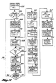
- Figure 13 details the flow logic of the calibration mode 1 subroutine.
- This subroutine is used to establish the amount of stray capacitance between the compensator LO Z and the HI Z wires of Figure 3, external to the tank. This requires that the compensator LO Z wire be disconnected at the point of tank entry.
- the stray capacitance is measured during density correction, along with any stray capacitance inside the tank, with the compensator, and would degrade accuracy if not accounted for in the density correction.
- the subroutine is entered at block 380. Then, a complete successive approximation procedure is run at block 382. This procedure utilizes the compensator measurement null sense and compensator measurement signal blocks of Figure 3 to measure capacitance, the difference being that the compensator LO Z wire is disconnected at the point of tank entry.
- the measured capacitance is stored as C stray at block 384 and the system returns to the main program at block 386.
- FIG 14 is a logic flow diagram of the calibration mode 2 subroutine.
- Calibration mode 2 is used to establish the entire amount of capacitance between the compensator LO Z wire and the HI Z wire of Figure 3, with the compensator in place but not wetted by fuel.
- the subroutine is entered at block 390.
- the successive approximation procedure utilizing the compensator measurement null sense and the compensator measurement signal blocks of Figure 3, is run.
- the resulting measured capacitance is stored, at block 394, as Cdry and this value is stored with reference to the particular tank of a multi-tank system. Thereafter, the system, at block 396, returns to the main program.
- FIG 15 is a logic flow diagram of the calibration mode 3 subroutine.
- the calibration mode 3 subroutine is used for processor-enhanced "full” adjustment of the gaging system.
- the processor-enhanced full adjust subroutine is understood with respect to the prior approach to calibrating a gage such that it reads "full" or some predetermined quantity of fuel at, or near, tank capacity.
- This adjustment has been done with the use of a specialized fuel gage calibration instrument. This instrument makes connection to all three wires connecting the gage to fuel probes and the compensator.
- One capacitance in the calibrating instrument is connected in parallel with the compensator. This added capacitance is made equal to the increase that would occur in the capacitance of the compensator if the compensator were immersed in fuel of nominal dielectric constant.
- a capacitance in the calibration instrument is connected in parallel with the fuel probes. This added capacitance is made equal to the increase that would occur in the capacitance of the fuel probes if a known volume of fuel was in the tank, with this fuel having the nominal dielectric constant. Since, in the design of the fuel gaging system, it was assumed that a certain density was associated with a nominal dielectric constant, a certain definite mass of fuel is thus simulated. The full adjustment of the gage is then set to cause the gage to read that simulated fuel mass.
- the deficiency in the above calibration procedure is that, if the tank was actually filled with fuel having the exact nominal dielectric constant, the increasing capacitance on the compensator side of the circuit would be different from the amount added during calibration, probably somewhat greater.
- the wetted stray capacitance always causes an increase, whereas the wetted unknown capacitance may represent either an increase or a reduction.
- the unknown capacitance is due to manufacturing tolerance on the dry capacitance of the compensator.
- the calibration mode 3 subroutine provides a means to use the same circuits as used for density correction to allow making the "full adjustment" of the gage with fuel in the tank.
- the LO Z wire that provides excitation voltage to the tank units is disconnected.
- a capacitance in the calibration instrument is connected to replace the function of the fuel probes. This substitute fuel probe capacitance simulates the sum of the dry capacitance of the fuel probes plus the amount of capacitance that would have been added during the earlier dry tank calibration procedure.
- the processor measures the dielectric constant of the fuel. It compares this result with the stored number for the nominal dielectric constant and establishes a correction factor such that the sum of the currents through the nominal compensator capacitance and through the correction factor control is equal to the current that would flow in the nominal compensator if it were immersed in fuel of nominal dielectric constant.
- the "full adjustment" on the gage is set to make the gage indicate the standard calibration mass represented by the simulated fuel probe capacitance in the calibration instrument. The principal difference between this procedure and that performed prior to this invention is that stray and unknown capacitance in the tank is wetted with fuel, thereby eliminating errors caused by capacitor variance due to component wetting.
- FIG. 15 details the logical steps.
- the calibration mode 3 subroutine is entered at block 400.
- a successive approximation procedure is performed at block 402, under the above described calibration mode 3 system configuration.
- the resulting value is stored, at block 404, as a value Ccal'
- the processor then recalls from memory the values of Cdry and C stra y at block 406.
- a dielectric constant is determined from the equation:
- the processor determines a correction value for the dielectric constant calculated at block 408. This happens at block 410.
- the resulting binary correction data is stored in output latches at block 412 and the system returns to the main program at block 414.
- an improved capacitive probe fuel gaging system has been disclosed.
- the system is capable of correcting for fuel which does not conform to the assumed fuel density/fuel dielectric constant relationship.
- the system is capable of correcting for errors caused by the attitude of the system, or of stray capacitances, or errors due to variance in capacitance when system components are wetted with fuel.
Landscapes
- Physics & Mathematics (AREA)
- Engineering & Computer Science (AREA)
- Power Engineering (AREA)
- Electromagnetism (AREA)
- Thermal Sciences (AREA)
- Fluid Mechanics (AREA)
- General Physics & Mathematics (AREA)
- Measurement Of Levels Of Liquids Or Fluent Solid Materials (AREA)
Abstract
Claims (8)


Applications Claiming Priority (1)
| Application Number | Priority Date | Filing Date | Title |
|---|---|---|---|
| PCT/US1982/001385 WO1984001428A1 (fr) | 1982-09-30 | 1982-09-30 | Systeme de mesure de carburant par jauge |
Publications (3)
| Publication Number | Publication Date |
|---|---|
| EP0120852A1 EP0120852A1 (fr) | 1984-10-10 |
| EP0120852A4 EP0120852A4 (fr) | 1986-07-23 |
| EP0120852B1 true EP0120852B1 (fr) | 1990-05-23 |
Family
ID=22168260
Family Applications (1)
| Application Number | Title | Priority Date | Filing Date |
|---|---|---|---|
| EP82903517A Expired EP0120852B1 (fr) | 1982-09-30 | 1982-09-30 | Systeme de mesure de carburant par jauge |
Country Status (5)
| Country | Link |
|---|---|
| US (1) | US4545020A (fr) |
| EP (1) | EP0120852B1 (fr) |
| JP (1) | JPS59501835A (fr) |
| DE (1) | DE3280180D1 (fr) |
| WO (1) | WO1984001428A1 (fr) |
Families Citing this family (45)
| Publication number | Priority date | Publication date | Assignee | Title |
|---|---|---|---|---|
| US4660152A (en) * | 1984-06-18 | 1987-04-21 | Xerox Corporation | System and method for monitoring and maintaining concentrate material in a fluid carrier |
| US4788648A (en) * | 1984-10-25 | 1988-11-29 | Air Products And Chemicals, Inc. | Method and system for measurement of a liquid level in a tank |
| JPS61198024A (ja) * | 1985-02-07 | 1986-09-02 | Nippon Koukuuki Kaihatsu Kyokai | 飛行体の燃料重量残量測定装置 |
| JPH0697176B2 (ja) * | 1986-12-17 | 1994-11-30 | 日本電装株式会社 | コイル式ゲ−ジを用いた変位量表示装置 |
| US4908783A (en) * | 1987-04-28 | 1990-03-13 | Simmonds Precision Products, Inc. | Apparatus and method for determining liquid levels |
| DE3725752A1 (de) * | 1987-08-04 | 1989-03-02 | Vdo Schindling | Verfahren und vorrichtung zur anzeige des fluessigkeitsniveaus in einem kraftfahrzeugtank |
| US5129415A (en) * | 1989-03-26 | 1992-07-14 | Robert Richard Runyon | System and method for automatically selecting one of a plurality of liquid supply receptacles as a source for a liquid dispensing apparatus |
| US5136250A (en) * | 1989-04-28 | 1992-08-04 | Seagate Technology, Inc. | Capacitance height gauge |
| US5138559A (en) * | 1989-08-28 | 1992-08-11 | The Boeing Company | System and method for measuring liquid mass quantity |
| US5051921A (en) * | 1989-11-30 | 1991-09-24 | David Sarnoff Research Center, Inc. | Method and apparatus for detecting liquid composition and actual liquid level |
| US5138880A (en) * | 1991-05-29 | 1992-08-18 | Lee/Maatuk Engineering, Inc. | Digital level sensing probe system |
| US5303179A (en) * | 1992-01-03 | 1994-04-12 | Simmonds Precision Products, Inc. | Method and apparatus for electronically simulating capacitors |
| EP0610050B1 (fr) * | 1993-02-01 | 1998-12-30 | Lee/Maatuk Engineering, Inc. | Sonde de mesure pour des liquides divers et pour des miroirs de liquides inclinés |
| US5485401A (en) * | 1993-06-14 | 1996-01-16 | Scully Signal Company | Method and apparatus for testing overfill protection devices |
| US5406843A (en) * | 1993-10-27 | 1995-04-18 | Kdi Corporation, Inc. | Digital liquid level sensing apparatus |
| US5613399A (en) * | 1993-10-27 | 1997-03-25 | Kdi Precision Products, Inc. | Method for liquid level detection |
| US6125696A (en) * | 1993-10-27 | 2000-10-03 | Kdi Precision Products, Inc. | Digital liquid level sensing apparatus |
| US5437184A (en) * | 1993-10-27 | 1995-08-01 | Kdi/Triangle Electronics, Inc. | Capacitive liquid level sensor having phase detecting circuitry |
| US6138508A (en) * | 1993-10-27 | 2000-10-31 | Kdi Precision Products, Inc. | Digital liquid level sensing apparatus |
| US5566572A (en) * | 1994-05-11 | 1996-10-22 | United Technologies Corporation | Circuitry to minimize stray capacitance effects in a capacitive liquid level measurement device |
| US5495745A (en) * | 1994-05-31 | 1996-03-05 | Simmonds Precision Products, Inc. | Apparatus and method for improving liquid gaging system using error compensation data |
| US6240778B1 (en) | 1998-03-02 | 2001-06-05 | Kdi Precision Products, Inc. | Liquid level point switch sensor |
| WO1999060539A1 (fr) * | 1998-05-21 | 1999-11-25 | Smiths Industries Aerospace | Dispositif de protection contre les etats defectueux pour les systemes de jaugeage de carburant |
| US6516661B1 (en) | 1999-01-28 | 2003-02-11 | Simmonds Precision Products, Inc. | Volume measurement system and method for volume element counting |
| RU2191142C1 (ru) * | 2001-10-10 | 2002-10-20 | Открытое акционерное общество "Техприбор" | Бортовая топливоизмерительная система с компенсацией по характеристическим параметрам топлива |
| RU2191355C1 (ru) * | 2001-10-10 | 2002-10-20 | Открытое акционерное общество "Техприбор" | Бортовая топливоизмерительная система с компенсацией по статической и динамической диэлектрическим проницаемостям топлива |
| RU2191356C1 (ru) * | 2001-10-10 | 2002-10-20 | Открытое акционерное общество "Техприбор" | Бортовая топливоизмерительная система с компенсацией по динамической диэлектрической проницаемости топлива |
| RU2191141C1 (ru) * | 2001-10-10 | 2002-10-20 | Открытое акционерное общество "Техприбор" | Бортовая топливоизмерительная система с компенсацией по температуре и статической диэлектрической проницаемости топлива |
| US6857313B2 (en) * | 2003-03-31 | 2005-02-22 | Rochester Gauges, Inc. | Self-calibrating capacitance gauge |
| US7726334B2 (en) | 2004-01-22 | 2010-06-01 | Rochester Gauges, Inc. | Service valve assembly having a stop-fill device and remote liquid level indicator |
| US7921873B2 (en) | 2004-01-22 | 2011-04-12 | Rochester Gauges, Inc. | Service valve assembly having a stop-fill device and a liquid level indicating dial |
| US7293578B2 (en) | 2004-01-22 | 2007-11-13 | Rochester Gauges, Inc. | Gauge assembly having a stop fill device |
| EP1677084A1 (fr) * | 2004-12-22 | 2006-07-05 | Roxer Industries S.A. | Capteur de niveau d'un liquide et méthode d'estimation. |
| FR2892509B1 (fr) * | 2005-10-26 | 2007-12-21 | Inergy Automotive Systems Res | Jauge capacitive pour reservoir a carburant |
| JP2009513963A (ja) * | 2005-10-26 | 2009-04-02 | イナジー・オートモーティブ・システムズ・リサーチ・(ソシエテ・アノニム) | 静電容量式ゲージ |
| USD583693S1 (en) | 2006-03-30 | 2008-12-30 | Rochester Gauges, Inc. | Dial assembly for a gauge |
| US7690323B2 (en) | 2007-10-31 | 2010-04-06 | Rochester Gauges, Inc. | Gauge head assembly with non-magnetic insert |
| US8086387B2 (en) * | 2008-06-18 | 2011-12-27 | The Boeing Company | System and method of fuel system optimization |
| US8515694B1 (en) | 2009-04-09 | 2013-08-20 | The Boeing Company | Methods and systems for gauging multiple hydrocarbon fuel mixtures |
| US10429228B2 (en) | 2013-05-13 | 2019-10-01 | The Boeing Company | Fuel level measurement using in-tank measuring system |
| US10175085B2 (en) | 2015-11-13 | 2019-01-08 | CiES, Inc. | Comparative fuel-level detection system |
| DE102015016775A1 (de) * | 2015-12-23 | 2017-06-29 | Audi Ag | Verfahren zum Betreiben einer Sensoranordnung für einen Fluidtank eines Kraftfahrzeugs sowie entsprechende Sensoranordnung |
| US10436933B2 (en) * | 2016-05-06 | 2019-10-08 | Baker Hughes, A Ge Company, Llc | Digital spectrometer for measuring ironizing radiation downhole |
| US11378438B2 (en) | 2018-03-19 | 2022-07-05 | Simmonds Precision Products, Inc. | Fluid measurement interface systems and methods |
| US11499485B2 (en) * | 2020-02-10 | 2022-11-15 | Raytheon Technologies Corporation | Engine control device and methods thereof |
Family Cites Families (16)
| Publication number | Priority date | Publication date | Assignee | Title |
|---|---|---|---|---|
| US2769338A (en) * | 1952-01-04 | 1956-11-06 | Honeywell Regulator Co | Fuel gage apparatus |
| US2866337A (en) * | 1954-08-31 | 1958-12-30 | Avien Inc | Compensated liquid quantity measuring apparatus |
| US3112647A (en) * | 1954-10-27 | 1963-12-03 | Liquidometer Corp | Measuring system with compensation for dielectric constant |
| GB1004759A (en) * | 1963-04-30 | 1965-09-15 | Smith & Sons Ltd S | Improvements in or relating to digital systems of the kind for providing an output representation of the value of a predetermined dependent variable |
| US3463980A (en) * | 1966-10-26 | 1969-08-26 | Simmonds Precision Products | Servo-controlled attitude error correction fluid gaging system |
| US3527096A (en) * | 1969-06-26 | 1970-09-08 | Simmonds Precision Products | Attitude error correction for a fluid gauging system |
| US4090408A (en) * | 1976-10-12 | 1978-05-23 | Hedrick Geoffrey S | Fluid quantity indicator |
| US4173893A (en) * | 1976-10-12 | 1979-11-13 | Hedrick Geoffrey S | Fluid quantity indicator |
| US4262531A (en) * | 1978-10-02 | 1981-04-21 | Smiths Industries Limited | Fluid-gauging methods and systems |
| US4235106A (en) * | 1978-12-08 | 1980-11-25 | Drexelbrook Controls, Inc. | System and method for obtaining compensated level measurements |
| US4258422A (en) * | 1979-05-04 | 1981-03-24 | Honeywell Inc. | Liquid gaging system |
| FR2459459A1 (fr) * | 1979-06-15 | 1981-01-09 | Intertechnique Sa | Perfectionnements aux procedes et dispositifs de jaugeage a capacite pour reservoir de combustible |
| US4383444A (en) * | 1980-04-21 | 1983-05-17 | Robertshaw Controls Company | Microprocessor based capacitance level detection system |
| US4352159A (en) * | 1980-05-14 | 1982-09-28 | Honeywell Inc. | Liquid gaging system lost sensor recovery |
| US4350039A (en) * | 1980-05-14 | 1982-09-21 | Honeywell Inc. | Liquid gaging system null balance circuitry |
| US4349882A (en) * | 1980-08-22 | 1982-09-14 | Veeder Industries Inc. | Liquid level measuring system |
-
1982
- 1982-09-30 DE DE8282903517T patent/DE3280180D1/de not_active Expired - Lifetime
- 1982-09-30 WO PCT/US1982/001385 patent/WO1984001428A1/fr not_active Ceased
- 1982-09-30 US US06/444,241 patent/US4545020A/en not_active Expired - Fee Related
- 1982-09-30 EP EP82903517A patent/EP0120852B1/fr not_active Expired
- 1982-09-30 JP JP57503496A patent/JPS59501835A/ja active Pending
Also Published As
| Publication number | Publication date |
|---|---|
| US4545020A (en) | 1985-10-01 |
| JPS59501835A (ja) | 1984-11-01 |
| EP0120852A4 (fr) | 1986-07-23 |
| DE3280180D1 (de) | 1990-06-28 |
| WO1984001428A1 (fr) | 1984-04-12 |
| EP0120852A1 (fr) | 1984-10-10 |
Similar Documents
| Publication | Publication Date | Title |
|---|---|---|
| US4545020A (en) | Fuel gaging system | |
| US4485673A (en) | Two-wire level measuring instrument | |
| US3534606A (en) | Fuel gage | |
| US5049878A (en) | Two-wire compensated level measuring instrument | |
| US4426616A (en) | Capacitive measurement system | |
| US4173893A (en) | Fluid quantity indicator | |
| EP0294026B1 (fr) | Mesure de quantité d'un liquide | |
| US4706203A (en) | Capacitive gauging method and apparatus | |
| EP0236681A2 (fr) | Procédé et appareil pour la mesure de débit gazeux et délivrance d'un signal corrigé | |
| US3970925A (en) | Direct reading reactance meter | |
| JPH0260986B2 (fr) | ||
| US5128611A (en) | Electronic electricity meter | |
| EP0609334B1 (fr) | DETECTEUR DE pH AUTODIAGNOSTIQUE | |
| US2866337A (en) | Compensated liquid quantity measuring apparatus | |
| US4823087A (en) | Salimeter | |
| US3463980A (en) | Servo-controlled attitude error correction fluid gaging system | |
| US4851831A (en) | Two-wire level measuring instrument | |
| AU711226B2 (en) | A method of and apparatus for analysing a signal | |
| US2789435A (en) | Capacitive liquid measuring apparatus | |
| US4525792A (en) | Unidirectional capacitive fluid-gauging systems | |
| US3022665A (en) | Liquid contents gauges | |
| US3416076A (en) | Voltage regulating means for impedance bridge measuring circuits | |
| CA1262372A (fr) | Methode de mesure des capacites, notamment des faibles capacites, a l'aide de deux references | |
| US3295372A (en) | Capacitance type fluid measuring apparatus | |
| GB2117520A (en) | Fuel gauging system |
Legal Events
| Date | Code | Title | Description |
|---|---|---|---|
| PUAI | Public reference made under article 153(3) epc to a published international application that has entered the european phase |
Free format text: ORIGINAL CODE: 0009012 |
|
| 17P | Request for examination filed |
Effective date: 19840528 |
|
| AK | Designated contracting states |
Kind code of ref document: A1 Designated state(s): DE FR GB NL |
|
| A4 | Supplementary search report drawn up and despatched |
Effective date: 19860723 |
|
| 17Q | First examination report despatched |
Effective date: 19880701 |
|
| GRAA | (expected) grant |
Free format text: ORIGINAL CODE: 0009210 |
|
| AK | Designated contracting states |
Kind code of ref document: B1 Designated state(s): DE FR GB NL |
|
| ET | Fr: translation filed | ||
| REF | Corresponds to: |
Ref document number: 3280180 Country of ref document: DE Date of ref document: 19900628 |
|
| PGFP | Annual fee paid to national office [announced via postgrant information from national office to epo] |
Ref country code: GB Payment date: 19900907 Year of fee payment: 9 |
|
| PGFP | Annual fee paid to national office [announced via postgrant information from national office to epo] |
Ref country code: FR Payment date: 19900928 Year of fee payment: 9 |
|
| PGFP | Annual fee paid to national office [announced via postgrant information from national office to epo] |
Ref country code: NL Payment date: 19900930 Year of fee payment: 9 |
|
| PGFP | Annual fee paid to national office [announced via postgrant information from national office to epo] |
Ref country code: DE Payment date: 19901031 Year of fee payment: 9 |
|
| PLBE | No opposition filed within time limit |
Free format text: ORIGINAL CODE: 0009261 |
|
| STAA | Information on the status of an ep patent application or granted ep patent |
Free format text: STATUS: NO OPPOSITION FILED WITHIN TIME LIMIT |
|
| 26N | No opposition filed | ||
| PG25 | Lapsed in a contracting state [announced via postgrant information from national office to epo] |
Ref country code: GB Effective date: 19910930 |
|
| PG25 | Lapsed in a contracting state [announced via postgrant information from national office to epo] |
Ref country code: NL Effective date: 19920401 |
|
| NLV4 | Nl: lapsed or anulled due to non-payment of the annual fee | ||
| GBPC | Gb: european patent ceased through non-payment of renewal fee | ||
| PG25 | Lapsed in a contracting state [announced via postgrant information from national office to epo] |
Ref country code: FR Effective date: 19920529 |
|
| PG25 | Lapsed in a contracting state [announced via postgrant information from national office to epo] |
Ref country code: DE Effective date: 19920602 |
|
| REG | Reference to a national code |
Ref country code: FR Ref legal event code: ST |