EP0120861B1 - Halter - Google Patents
Halter Download PDFInfo
- Publication number
- EP0120861B1 EP0120861B1 EP19830901263 EP83901263A EP0120861B1 EP 0120861 B1 EP0120861 B1 EP 0120861B1 EP 19830901263 EP19830901263 EP 19830901263 EP 83901263 A EP83901263 A EP 83901263A EP 0120861 B1 EP0120861 B1 EP 0120861B1
- Authority
- EP
- European Patent Office
- Prior art keywords
- holder means
- stirrup
- objects
- holder
- pairs
- Prior art date
- Legal status (The legal status is an assumption and is not a legal conclusion. Google has not performed a legal analysis and makes no representation as to the accuracy of the status listed.)
- Expired
Links
- 238000005259 measurement Methods 0.000 claims description 4
- 210000000078 claw Anatomy 0.000 claims description 2
- 238000010276 construction Methods 0.000 description 2
- 238000010616 electrical installation Methods 0.000 description 1
- 238000003780 insertion Methods 0.000 description 1
- 230000037431 insertion Effects 0.000 description 1
- 238000009434 installation Methods 0.000 description 1
- 230000014759 maintenance of location Effects 0.000 description 1
- 239000000463 material Substances 0.000 description 1
- 238000000034 method Methods 0.000 description 1
- 229920003023 plastic Polymers 0.000 description 1
- 239000004033 plastic Substances 0.000 description 1
- 239000000126 substance Substances 0.000 description 1
- XLYOFNOQVPJJNP-UHFFFAOYSA-N water Substances O XLYOFNOQVPJJNP-UHFFFAOYSA-N 0.000 description 1
Images
Classifications
-
- A—HUMAN NECESSITIES
- A63—SPORTS; GAMES; AMUSEMENTS
- A63C—SKATES; SKIS; ROLLER SKATES; DESIGN OR LAYOUT OF COURTS, RINKS OR THE LIKE
- A63C11/00—Accessories for skiing or snowboarding
-
- F—MECHANICAL ENGINEERING; LIGHTING; HEATING; WEAPONS; BLASTING
- F16—ENGINEERING ELEMENTS AND UNITS; GENERAL MEASURES FOR PRODUCING AND MAINTAINING EFFECTIVE FUNCTIONING OF MACHINES OR INSTALLATIONS; THERMAL INSULATION IN GENERAL
- F16B—DEVICES FOR FASTENING OR SECURING CONSTRUCTIONAL ELEMENTS OR MACHINE PARTS TOGETHER, e.g. NAILS, BOLTS, CIRCLIPS, CLAMPS, CLIPS OR WEDGES; JOINTS OR JOINTING
- F16B2/00—Friction-grip releasable fastenings
- F16B2/005—Means to increase the friction-coefficient
-
- F—MECHANICAL ENGINEERING; LIGHTING; HEATING; WEAPONS; BLASTING
- F16—ENGINEERING ELEMENTS AND UNITS; GENERAL MEASURES FOR PRODUCING AND MAINTAINING EFFECTIVE FUNCTIONING OF MACHINES OR INSTALLATIONS; THERMAL INSULATION IN GENERAL
- F16B—DEVICES FOR FASTENING OR SECURING CONSTRUCTIONAL ELEMENTS OR MACHINE PARTS TOGETHER, e.g. NAILS, BOLTS, CIRCLIPS, CLAMPS, CLIPS OR WEDGES; JOINTS OR JOINTING
- F16B2/00—Friction-grip releasable fastenings
- F16B2/20—Clips, i.e. with gripping action effected solely by the inherent resistance to deformation of the material of the fastening
- F16B2/22—Clips, i.e. with gripping action effected solely by the inherent resistance to deformation of the material of the fastening of resilient material, e.g. rubbery material
-
- F—MECHANICAL ENGINEERING; LIGHTING; HEATING; WEAPONS; BLASTING
- F16—ENGINEERING ELEMENTS AND UNITS; GENERAL MEASURES FOR PRODUCING AND MAINTAINING EFFECTIVE FUNCTIONING OF MACHINES OR INSTALLATIONS; THERMAL INSULATION IN GENERAL
- F16B—DEVICES FOR FASTENING OR SECURING CONSTRUCTIONAL ELEMENTS OR MACHINE PARTS TOGETHER, e.g. NAILS, BOLTS, CIRCLIPS, CLAMPS, CLIPS OR WEDGES; JOINTS OR JOINTING
- F16B7/00—Connections of rods or tubes, e.g. of non-circular section, mutually, including resilient connections
- F16B7/04—Clamping or clipping connections
- F16B7/0433—Clamping or clipping connections for rods or tubes being in parallel relationship
-
- F—MECHANICAL ENGINEERING; LIGHTING; HEATING; WEAPONS; BLASTING
- F16—ENGINEERING ELEMENTS AND UNITS; GENERAL MEASURES FOR PRODUCING AND MAINTAINING EFFECTIVE FUNCTIONING OF MACHINES OR INSTALLATIONS; THERMAL INSULATION IN GENERAL
- F16L—PIPES; JOINTS OR FITTINGS FOR PIPES; SUPPORTS FOR PIPES, CABLES OR PROTECTIVE TUBING; MEANS FOR THERMAL INSULATION IN GENERAL
- F16L3/00—Supports for pipes, cables or protective tubing, e.g. hangers, holders, clamps, cleats, clips, brackets
- F16L3/22—Supports for pipes, cables or protective tubing, e.g. hangers, holders, clamps, cleats, clips, brackets specially adapted for supporting a number of parallel pipes at intervals
- F16L3/237—Supports for pipes, cables or protective tubing, e.g. hangers, holders, clamps, cleats, clips, brackets specially adapted for supporting a number of parallel pipes at intervals for two pipes
Definitions
- the present invention relates to a holder for securing two, elongate objects firmly together, parallel with one another, in a readily detachable manner.
- Fittings and particularly pipe fittings, which include open, stirrup-like holding means and which are arranged to be twisted or rotated relative to the pipe in order to grip and hold the same are known to the art, see DEA2 334 913.
- This specification also proposes to join two such fittings together, for connecting two pipes in a manner such that they extend parallel to one another. To this end, these fittings must be rotatable relative to one another, so that they can be rotated in mutually opposite directions relative to the pipes. Consequently, such fittings cannot be used successively to connect pairs of ski-sticks rigidly together.
- An object of the present invention is to provide a holder of the kind described, which comprises stirrup-like holding means by means of which two elongate objects can be firmly gripped and rigidly held together in response to a relative rotation of the objects and the holder, in mutually the same direction.
- a holder which in accordance with the holder of the above mentioned DE-A-23 34 913 includes four stirrup-like holder means each with a circumferential opening and arranged in axially spaced pairs with respect to the axial direction of the attached elongate objects, the axial distance between the two pairs of said holder means being such as to permit said elongate objects to be passed in between the pairs of said holder means, whereafter said elongate objects can be caused to pass through the openings of said holder means, to be gripped and firmly held thereby, by relative rotation of about 90° between said elongate objects and said holder means, and which according to the present invention is further characterised in that said device further includes a fixed centre piece having non-rotatably connected thereto said four stirrup-like holder means in such a way that the openings of each pair of said holder means face in the same direction, while the openings of the respective pairs of said holder means face in opposite directions, so that said elongate
- the stirrup-like holder means are preferably slightly flexible and formed integrally with the centre piece. As a result of this flexibility of the holder means, the cross-dimension of the openings presented thereby can be slightly smaller than the corresponding cross-dimensions of the objects they are intended to hold. On the other hand, the distance between the pairs of stirrup-like holder means is suitably slightly greater than the corresponding cross-dimensions of the objects to be held by said holder. In order to ensure reliable retention of the elongate objects in the holder, the ends of the stirrup-like holder means extend beyond the longitudinal centre plane dividing the spaces enclosed by said holder means.
- the stirrup-like portion of respective holder means suitably has the form of a claw of part-circular cross-section, where the radius of curvature is equal to, or slightly smaller than half the diameter of the objects to be held.
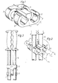
- the holder illustrated in Figure 1 is fully symmetrical, and includes a centre piece 1, which has arranged at both ends thereof a pair of claw-like holding stirrups 2 and 3, of which the stirrups of one pair face in a direction opposite to that of the stirrup of the other pair.
- the openings of the stirrups in one pair face in mutually the same direction, while the openings of one pair of stirrups face in a direction opposite to the openings of the other pair of stirrups.
- the reference 4 identifies a hole through which a fastener can be passed, for attaching the holder to a support surface, or by means of which the holder can be hung on, for example, a display frame-structure.
- the holder illustrated in Figure 1 is particularly intended for firmly connecting together two circular-cylindrical objects, such as pipes, electrical cables or the like, so that the objects lie parallel with one another.
- the illustrated holder is in the form of a one piece structure of plastics material, and the claw-shaped stirrups 2 and 3 have a certain degree of resiliency.
- the smallest cross-measurement A of the stirrup opening can be somewhat smaller than the diameter of the object to be held.
- the distance B between the pairs of stirrups is suitably somewhat greater than the diameter of the objects to be held, thereby, among other things, to facilitate insertion of the objects into said stirrups, and to permit some variation in the cross-dimensions of the objects.
- the diameter C of the part-cylindrical space defined by each stirrup is substantially equal to, or slightly smaller than the diameter of the objects to be held.
- the free ends of the stirrups suitably extend beyond the geometric centre line of the spaces embraced by said stirrups.
- FIGS 2 and 3 illustrate how a holder according to the invention can be used to hold two ski-sticks 5 together.
- the ski-sticks are inserted into the space located between the two stirrup pairs 2, 3, this space being somewhat larger than the diameter of the ski-sticks 5, in accordance with the above.
- the ski-sticks are then rotated through substantially 90°, in mutually the same direction relative to the holder, as indicated by the arrow D.
- the holder may be rotated relative to the sticks, this being the most suitable procedure in practice.
- the important factor, however, is that a relative rotation can be achieved between sticks and holder.
- the opening through which the ski-sticks are intended to pass may narrow and have a smallest cross-dimension which is somewhat smaller than the diameter of the ski-sticks, thereby to provide effective locking of the sticks once they have been snapped into- the position shown in chain lines in Figure 2.
- Figure 3 illustrates how the ski-sticks are held in the position desired relative to one another, subsequent to rotating the holder in the manner shown in Figure 2.
- the ski-sticks can be readily transported or stored when held in the illustrated manner, and the holder may also be used for placing ski-sticks on display in a sports shop, in which case a spear-shaped fastener is passed through the hole 4.
- the described and illustrated holder may be used in connections other than that of holding two ski-sticks together.
- the holder may be used in civil engineering fields, for holding pairs of pipes together, such as cold and hot water pipes, the holder being screwed to a supporting surface by means of a screw passed through the hole 4.
- the holder may also be used for permanent or temporary cable installations, as well, for example, as a cable lock, i.e. for locking two cables together, for example when using an extension cable, to obviate the need of tying the ends of cables together, so as to ensure that the male plug is not withdrawn from the female socket.
- the holder may also be used as a keeper, for securing the end of a coiled cable, or a cable layed or held in some other way.
- the stirrups 2 and 3 may be totally rigid.
- the holder may also be used to hold objects of other cross-sectional shapes.
- the curvature of the stirrups 2 and 3 is adapted to suit the object in question.
- the aforesaid symmetrical construction may be changed to an asymmetrical construction, such that the curvature of the stirrups 2 and 3 on one side of the centre piece is different to that of the stirrups on the other side of said centre piece, so that the holder can be used to connect together two objects of mutually different cross-sections.
- the holder can also be used to connect an elongate object to a fixed support or the like. As will be understood, the holder may also be used to connect together bundles of objects.
- the inner surfaces of the stirrups may be coated or lined with a friction-increasing substance, or may be provided with friction-increasing means.
- the stirrups may have any desired shape, and may optionally be produced as separate elements and subsequently attached to the centre piece, or directly to one another.
Landscapes
- Engineering & Computer Science (AREA)
- General Engineering & Computer Science (AREA)
- Mechanical Engineering (AREA)
- Mutual Connection Of Rods And Tubes (AREA)
- Clamps And Clips (AREA)
- Supports For Pipes And Cables (AREA)
Claims (7)
Priority Applications (1)
| Application Number | Priority Date | Filing Date | Title |
|---|---|---|---|
| AT83901263T ATE25133T1 (de) | 1982-04-22 | 1983-04-18 | Halter. |
Applications Claiming Priority (2)
| Application Number | Priority Date | Filing Date | Title |
|---|---|---|---|
| SE8202541A SE428491B (sv) | 1982-04-22 | 1982-04-22 | Fasthallningsanordning |
| SE8202541 | 1982-04-22 |
Publications (2)
| Publication Number | Publication Date |
|---|---|
| EP0120861A1 EP0120861A1 (de) | 1984-10-10 |
| EP0120861B1 true EP0120861B1 (de) | 1987-01-21 |
Family
ID=20346611
Family Applications (1)
| Application Number | Title | Priority Date | Filing Date |
|---|---|---|---|
| EP19830901263 Expired EP0120861B1 (de) | 1982-04-22 | 1983-04-18 | Halter |
Country Status (5)
| Country | Link |
|---|---|
| EP (1) | EP0120861B1 (de) |
| JP (1) | JPS59500651A (de) |
| DE (1) | DE3369369D1 (de) |
| SE (1) | SE428491B (de) |
| WO (1) | WO1983003880A1 (de) |
Families Citing this family (6)
| Publication number | Priority date | Publication date | Assignee | Title |
|---|---|---|---|---|
| DE9201892U1 (de) * | 1992-02-14 | 1992-04-02 | Hermann Kleinhuis GmbH & Co KG, 5880 Lüdenscheid | Rohrschnappschelle für Elektroinstallationsrohre |
| FR2839348A1 (fr) * | 2002-05-03 | 2003-11-07 | Denis Doistau | Agencement pour l'assemblage d'elements de mobilier de bureau |
| FI117543B (fi) * | 2005-03-31 | 2006-11-30 | Olecranon Oy | Pidike |
| GB0619105D0 (en) * | 2006-09-28 | 2006-11-08 | Oxford Plastic Sys Ltd | Clipping device |
| CN107131192A (zh) * | 2017-06-16 | 2017-09-05 | 海盐猛士螺钉有限责任公司 | 螺纹杆连接器 |
| US20200232600A1 (en) * | 2019-01-17 | 2020-07-23 | Dwight Dixon | Pole Coupling Assembly |
Family Cites Families (6)
| Publication number | Priority date | Publication date | Assignee | Title |
|---|---|---|---|---|
| FR1286788A (fr) * | 1961-01-25 | 1962-03-09 | Support de tuyauterie et de barre | |
| FR1526230A (fr) * | 1967-04-12 | 1968-05-24 | Attache-support de tuyauterie perfectionnée | |
| JPS5432742Y2 (de) * | 1972-05-10 | 1979-10-11 | ||
| DE2334913A1 (de) * | 1973-07-10 | 1975-01-23 | Bassan & Cie | Vorrichtung zum befestigen zylindrischer, insbesondere rohrfoermiger teile auf einer beliebigen unterlage |
| JPS5137575U (de) * | 1974-09-11 | 1976-03-19 | ||
| GB2037862A (en) * | 1978-12-18 | 1980-07-16 | Leung Yat Shing Trading As On | Clip for Concrete-reinforcing Rods |
-
1982
- 1982-04-22 SE SE8202541A patent/SE428491B/sv not_active IP Right Cessation
-
1983
- 1983-04-18 JP JP58501359A patent/JPS59500651A/ja active Pending
- 1983-04-18 EP EP19830901263 patent/EP0120861B1/de not_active Expired
- 1983-04-18 WO PCT/SE1983/000144 patent/WO1983003880A1/en not_active Ceased
- 1983-04-18 DE DE8383901263T patent/DE3369369D1/de not_active Expired
Also Published As
| Publication number | Publication date |
|---|---|
| DE3369369D1 (en) | 1987-02-26 |
| EP0120861A1 (de) | 1984-10-10 |
| JPS59500651A (ja) | 1984-04-19 |
| WO1983003880A1 (en) | 1983-11-10 |
| SE428491B (sv) | 1983-07-04 |
Similar Documents
| Publication | Publication Date | Title |
|---|---|---|
| US3560027A (en) | Coupling assembly | |
| US5745958A (en) | Cable-bundling band | |
| US5161836A (en) | Pipe connecting apparatus | |
| US6263895B1 (en) | Quick connect system | |
| US3226069A (en) | Hanger for cylindrical conduits and the like | |
| US4248459A (en) | Flexible conduit system | |
| US4470622A (en) | Flexible conduit system | |
| US3417951A (en) | Pipe support | |
| EP1369630A1 (de) | Kabelbinder | |
| US3564667A (en) | Ski clamp | |
| EP0120861B1 (de) | Halter | |
| US5430252A (en) | Electrical fitting | |
| US5328384A (en) | Extension cord retaining device | |
| US4995647A (en) | Portal semicylindrical electrical connector | |
| CA2210105C (en) | Plug connector | |
| US4225103A (en) | Pipe clamp device | |
| US20100068913A1 (en) | Coupler for holding a socket and plug of two electrical cords together | |
| US4524999A (en) | Flexible conduit system | |
| CA2050387C (en) | Neutral conductor clamp | |
| US4232419A (en) | Articulated plumbers snake | |
| US5454662A (en) | Connector for coupling the pipes of a pipe corral | |
| US7090175B1 (en) | Insulating wire separator apparatus for piping systems | |
| US5470249A (en) | Electrical power cord retaining connector | |
| US11572979B2 (en) | Grease gun mounting assembly | |
| JPS5812514Y2 (ja) | 蛇管の取付け具 |
Legal Events
| Date | Code | Title | Description |
|---|---|---|---|
| PUAI | Public reference made under article 153(3) epc to a published international application that has entered the european phase |
Free format text: ORIGINAL CODE: 0009012 |
|
| 17P | Request for examination filed |
Effective date: 19840516 |
|
| AK | Designated contracting states |
Kind code of ref document: A1 Designated state(s): AT BE CH DE FR GB LI NL |
|
| GRAA | (expected) grant |
Free format text: ORIGINAL CODE: 0009210 |
|
| AK | Designated contracting states |
Kind code of ref document: B1 Designated state(s): AT BE CH DE FR GB LI NL |
|
| PG25 | Lapsed in a contracting state [announced via postgrant information from national office to epo] |
Ref country code: AT Effective date: 19870121 |
|
| REF | Corresponds to: |
Ref document number: 25133 Country of ref document: AT Date of ref document: 19870215 Kind code of ref document: T |
|
| REF | Corresponds to: |
Ref document number: 3369369 Country of ref document: DE Date of ref document: 19870226 |
|
| ET | Fr: translation filed | ||
| PLBE | No opposition filed within time limit |
Free format text: ORIGINAL CODE: 0009261 |
|
| STAA | Information on the status of an ep patent application or granted ep patent |
Free format text: STATUS: NO OPPOSITION FILED WITHIN TIME LIMIT |
|
| 26N | No opposition filed | ||
| PG25 | Lapsed in a contracting state [announced via postgrant information from national office to epo] |
Ref country code: GB Effective date: 19880418 |
|
| GBPC | Gb: european patent ceased through non-payment of renewal fee | ||
| PGFP | Annual fee paid to national office [announced via postgrant information from national office to epo] |
Ref country code: FR Payment date: 19910429 Year of fee payment: 9 |
|
| PGFP | Annual fee paid to national office [announced via postgrant information from national office to epo] |
Ref country code: NL Payment date: 19910430 Year of fee payment: 9 |
|
| PGFP | Annual fee paid to national office [announced via postgrant information from national office to epo] |
Ref country code: DE Payment date: 19910502 Year of fee payment: 9 |
|
| PGFP | Annual fee paid to national office [announced via postgrant information from national office to epo] |
Ref country code: BE Payment date: 19910514 Year of fee payment: 9 |
|
| PGFP | Annual fee paid to national office [announced via postgrant information from national office to epo] |
Ref country code: CH Payment date: 19910515 Year of fee payment: 9 |
|
| PG25 | Lapsed in a contracting state [announced via postgrant information from national office to epo] |
Ref country code: LI Effective date: 19920430 Ref country code: CH Effective date: 19920430 Ref country code: BE Effective date: 19920430 |
|
| BERE | Be: lapsed |
Owner name: FRANZEN PER-OLOV Effective date: 19920430 Owner name: KARNHAG LARS OWE Effective date: 19920430 |
|
| PG25 | Lapsed in a contracting state [announced via postgrant information from national office to epo] |
Ref country code: NL Effective date: 19921101 |
|
| NLV4 | Nl: lapsed or anulled due to non-payment of the annual fee | ||
| PG25 | Lapsed in a contracting state [announced via postgrant information from national office to epo] |
Ref country code: FR Effective date: 19921230 |
|
| REG | Reference to a national code |
Ref country code: CH Ref legal event code: PL |
|
| PG25 | Lapsed in a contracting state [announced via postgrant information from national office to epo] |
Ref country code: DE Effective date: 19930101 |
|
| REG | Reference to a national code |
Ref country code: FR Ref legal event code: ST |