EP0120904B1 - Goujon concu pour l'assemblage de parties de mobilier - Google Patents
Goujon concu pour l'assemblage de parties de mobilier Download PDFInfo
- Publication number
- EP0120904B1 EP0120904B1 EP83903175A EP83903175A EP0120904B1 EP 0120904 B1 EP0120904 B1 EP 0120904B1 EP 83903175 A EP83903175 A EP 83903175A EP 83903175 A EP83903175 A EP 83903175A EP 0120904 B1 EP0120904 B1 EP 0120904B1
- Authority
- EP
- European Patent Office
- Prior art keywords
- dowel
- protruding part
- receiving part
- parts
- head
- Prior art date
- Legal status (The legal status is an assumption and is not a legal conclusion. Google has not performed a legal analysis and makes no representation as to the accuracy of the status listed.)
- Expired
Links
- 238000003780 insertion Methods 0.000 abstract description 3
- 230000037431 insertion Effects 0.000 abstract description 3
- 239000000463 material Substances 0.000 description 3
- 238000004519 manufacturing process Methods 0.000 description 2
- 239000004952 Polyamide Substances 0.000 description 1
- 230000001934 delay Effects 0.000 description 1
- 238000006073 displacement reaction Methods 0.000 description 1
- 230000000694 effects Effects 0.000 description 1
- 238000011010 flushing procedure Methods 0.000 description 1
- 238000002347 injection Methods 0.000 description 1
- 239000007924 injection Substances 0.000 description 1
- 238000000034 method Methods 0.000 description 1
- 229920002647 polyamide Polymers 0.000 description 1
- 230000001681 protective effect Effects 0.000 description 1
Images

Classifications
-
- F—MECHANICAL ENGINEERING; LIGHTING; HEATING; WEAPONS; BLASTING
- F16—ENGINEERING ELEMENTS AND UNITS; GENERAL MEASURES FOR PRODUCING AND MAINTAINING EFFECTIVE FUNCTIONING OF MACHINES OR INSTALLATIONS; THERMAL INSULATION IN GENERAL
- F16B—DEVICES FOR FASTENING OR SECURING CONSTRUCTIONAL ELEMENTS OR MACHINE PARTS TOGETHER, e.g. NAILS, BOLTS, CIRCLIPS, CLAMPS, CLIPS OR WEDGES; JOINTS OR JOINTING
- F16B12/00—Jointing of furniture or the like, e.g. hidden from exterior
- F16B12/10—Jointing of furniture or the like, e.g. hidden from exterior using pegs, bolts, tenons, clamps, clips, or the like
- F16B12/12—Jointing of furniture or the like, e.g. hidden from exterior using pegs, bolts, tenons, clamps, clips, or the like for non-metal furniture parts, e.g. made of wood, of plastics
- F16B12/26—Jointing of furniture or the like, e.g. hidden from exterior using pegs, bolts, tenons, clamps, clips, or the like for non-metal furniture parts, e.g. made of wood, of plastics using snap-action elements
-
- F—MECHANICAL ENGINEERING; LIGHTING; HEATING; WEAPONS; BLASTING
- F16—ENGINEERING ELEMENTS AND UNITS; GENERAL MEASURES FOR PRODUCING AND MAINTAINING EFFECTIVE FUNCTIONING OF MACHINES OR INSTALLATIONS; THERMAL INSULATION IN GENERAL
- F16B—DEVICES FOR FASTENING OR SECURING CONSTRUCTIONAL ELEMENTS OR MACHINE PARTS TOGETHER, e.g. NAILS, BOLTS, CIRCLIPS, CLAMPS, CLIPS OR WEDGES; JOINTS OR JOINTING
- F16B2200/00—Constructional details of connections not covered for in other groups of this subclass
- F16B2200/30—Dovetail-like connections
-
- F—MECHANICAL ENGINEERING; LIGHTING; HEATING; WEAPONS; BLASTING
- F16—ENGINEERING ELEMENTS AND UNITS; GENERAL MEASURES FOR PRODUCING AND MAINTAINING EFFECTIVE FUNCTIONING OF MACHINES OR INSTALLATIONS; THERMAL INSULATION IN GENERAL
- F16B—DEVICES FOR FASTENING OR SECURING CONSTRUCTIONAL ELEMENTS OR MACHINE PARTS TOGETHER, e.g. NAILS, BOLTS, CIRCLIPS, CLAMPS, CLIPS OR WEDGES; JOINTS OR JOINTING
- F16B2200/00—Constructional details of connections not covered for in other groups of this subclass
- F16B2200/69—Redundant disconnection blocking means
-
- Y—GENERAL TAGGING OF NEW TECHNOLOGICAL DEVELOPMENTS; GENERAL TAGGING OF CROSS-SECTIONAL TECHNOLOGIES SPANNING OVER SEVERAL SECTIONS OF THE IPC; TECHNICAL SUBJECTS COVERED BY FORMER USPC CROSS-REFERENCE ART COLLECTIONS [XRACs] AND DIGESTS
- Y10—TECHNICAL SUBJECTS COVERED BY FORMER USPC
- Y10T—TECHNICAL SUBJECTS COVERED BY FORMER US CLASSIFICATION
- Y10T403/00—Joints and connections
- Y10T403/55—Member ends joined by inserted section
- Y10T403/555—Angle section
-
- Y—GENERAL TAGGING OF NEW TECHNOLOGICAL DEVELOPMENTS; GENERAL TAGGING OF CROSS-SECTIONAL TECHNOLOGIES SPANNING OVER SEVERAL SECTIONS OF THE IPC; TECHNICAL SUBJECTS COVERED BY FORMER USPC CROSS-REFERENCE ART COLLECTIONS [XRACs] AND DIGESTS
- Y10—TECHNICAL SUBJECTS COVERED BY FORMER USPC
- Y10T—TECHNICAL SUBJECTS COVERED BY FORMER US CLASSIFICATION
- Y10T403/00—Joints and connections
- Y10T403/70—Interfitted members
- Y10T403/7016—Diametric end slot is joint component
Definitions
- the invention relates to a dowel for assembling adjacent ends preferably of furniture parts and constructed in such a manner that it is capable of being fastened in a bore of the individual furniture part, an exposed head by the assembling being constructed to engage an adjacent head of a similar dowel of another furniture part, the head of the dowel comprising a protruding part as well as a receiving part.
- US-A 3 985 083 discloses a connector for use in constructing book shelves etc., one embodiment of which comprises a head having a protruding and receiving part. However, although two or more of these connectors may be joined together, they need an additional clamping means to ensure that they are substantially, immovably attached.
- the dowel according to the invention is characterised by said parts being shaped so that the protruding part of the dowel may be snapped into the receiving part of a similar dowel and be maintained substantially immovable herein.
- the head may be tapered so that it comprises substantially two plane surfaces forming an angle, preferably of 90°, with each other and intersecting immediately adjacent to the middle of the head, and the protruding part and the receiving part may be associated with respective plane surfaces and may each be of such a shape that the corresponding plane surface abuts the plane surface of the corresponding part of the other similar dowel. It is hereby made possible in a very simple manner to assemble the angular parts in question with the desired mutual angles, of e.g. 90°.
- the dowel according to the invention may also be of a substantially circular cross-section and may be hollow; the receiving part may be constituted by a centrally located, radial, rectangular aperture which is formed in the corresponding plane surface extending from the intersection of the two plane surfaces, and which inwardly in the dowel leads into the inner cavity, and the protruding part may be of a corresponding, substantially rectangular shape with a corresponding, central location on its adjacent plane surface, and the protruding part at the outer end may comprise an enlargement adapted to be received in the inner cavity of a corresponding dowel.
- a dowel is hereby obtained which is very simple to use and easy to manufacture.
- the dowel may comprise axial slits issuing from the receiving part, whereby said receiving part in a simple way is made resilient or yielding to effect snap action, even if the material used for the manufacture of the dowel is comparatively hard.
- the dowel may comprise a centrally located slit through the protruding part, said slit extending symmetrically around an axial plane through the central axis of the dowel, whereby the snap action may be effected in a simple manner at the resilient, protruding part.
- the dowel may comprise a locking device, which by actuation from the outside is adapted to pass from the inner of the dowel into the central slit through the protruding part and to abut opposite sides of the slit.
- a locking device which by actuation from the outside is adapted to pass from the inner of the dowel into the central slit through the protruding part and to abut opposite sides of the slit.
- the protruding part viewed in the direction of the intersection of the two plane surfaces may be triangular, and the two adjacent free surfaces of the protruding part may be adapted when engaging a second dowel to abut corresponding surfaces at the receiving part.
- a good support of the joined dowels is hereby obtained so that together they show good stability.
- the dowel may have a detachable cap of a complemental head, said cap consisting of a receiving part and a protruding part. It is hereby possible to hide unused dowels conveniently by mounting such a cap.
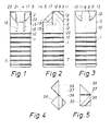
- the dowel shown in Figs. 1-3 is of a substantially cylindrical shape with a row of circumferential ribs 1 shaped around the bottom area of the dowel and adapted for maintaining the dowel in a corresponding aperture in a furniture part.
- the opposite upper end, the head 2, of the dowel comprises a protruding part 3 and a receiving part 4.
- the protruding part and the receiving part are associated with respective plane surfaces 5, 6 intersecting under an angle of 90° along a line perpendicular to the axis 7 of the dowel.
- the protruding part 3 is as shown in Fig. 2 triangular, viewed in a direction parallel to the line of intersection of the plane surfaces.
- the protruding part 3 is symmetrical in relation to the plane containing the central axis 7 and located perpendicular to the adjacent plane surface 6.
- the protruding part 3 is tapered slightly in a direction towards the free edge.
- the protruding part 3 has a recess 12, which on the outside is connected with the tapered surfaces by an outwardly extending side 13 which in its longitudinal direction extends parallel to the plane surface 6.
- the receiving part 4 (cf. especially Fig. 1) is shaped as a slit extending into the corresponding plane surface 5 and symmetrically around the same plane as the one around which the protruding part is symmetrical. Besides the receiving part 4 is shaped to receive by snapping a protruding part 3 of a corresponding dowel, as the corresponding plane surfaces 5 and 6 will abut each other, and simultaneously the sides 13, which on the outside define the recess 12 of the corresponding protruding part, abut corresponding sides 14 within the receiving part 4.
- the dowel is hollow, and the slit-shaped receiving part is thereby directly connected to the inner cavity of the dowel.
- the dowel comprises axially extending slits 15, 16, 17 adjacent the receiving part 4.
- the slits 15,16 extend from the bottom end of the receiving part 4 in a direction away from the head of the dowel, whereas the slit 17 is adjacentto the upper end of the receiving part 4, said slit, as it appears from Figs. 1 and 2, extending diagonally parallel to the line of intersection of the two plane surfaces 5,6.
- Said slits 15,16,17 enable the parts of the dowel abutting the receiving part 4 to yield when a protruding part 3 is inserted, despite the fact that the dowel, which is suitably injection moulded, is made of a relatively hard material, e.g. polyamide.
- the dowel may of course also be made of other materials.
- the receiving part is at the bottom limited by a plane surface 19 extending perpendicular to the central axis of the dowel as far as the connection of the receiving part with the inner cavity 20.
- the dowel is shaped in such a way that the upper part of the receiving part 4 is defined by a plane surface 21 extending perpendicularto the symmetry plane of the receiving part and containing the central axis 7 of the dowel.
- a protruding part 3 in the receiving part 4 is as indicated in Fig. 1 externally shaped with bevelled surfaces 22 and 23, respectively, inclining towards each other.
- a cap 36 may be attached to the dowel (cf. Figs. 4 and 5), said cap comprising a protruding part 38 and a receiving part 39 corresponding completely to the protruding part 3 and the receiving part 4 of the corresponding dowel.
- the cap is shaped in such a manner that a hinge 37 is located between the two parts containing the protruding part 38 and the receiving part 39, respectively.
- Said hinge 37 which is advantageously integral with the remaining part of the cap 36, permit the cap to be adapted to be placed on one and the same dowel as well as to be placed in engagement with adjacent parts of two dowels in a joint, as described more explicitly below.
- the cap may moreover be of many different shapes and may optionally form part of a protective strip for protecting the edge of a furniture part, on which exposed dowel parts are located.
- the embodiment of the dowel according to the invention shown in Figs. 1-3 is as mentioned constructed so that the receiving part 4 permits the yielding or resiliency necessary for the snap action.
- the necessary resiliency is, however, ensured in connection with the protruding part 3.
- the embodiment shown here corresponds to the embodiment shown in Figs. 1-3 apart from the fact that it does not comprise the slits 15,16, and 17 connected to the receiving part 4, but on the contrary a slit 24 extending through the centre of the protruding part 3 symmetrically around the symmetry plane of the protruding part.
- the slit 24 extends as far as the plane containing the corresponding plane surface 6.
- the slit 24 permits the protruding part to yield inward towards the central plane of the slit.
- the resiliency described here in connection with the protruding part 3 also enables the dowel to be provided with a locking device 25 (cf. Figs. 7-10), which in the case shown consists of a head 26 and an elongated annular shank 27.
- the locking device is of such a length, that its head is located a distance outside the bottom end of the dowel, whereas the shank 27 extends to the close vicinity of the bottom area of the receiving part, as shown in Fig. 8.
- the locking device 25 is steered by means (not shown) in such a way that it is easily displaceable and is always located in the symmetry plane of the receiving part, substantially parallel to the axis of the dowel.
- the shank is of such a shape that it may pass unhindered into the slit 24 in a protruding part 3 located in the receiving part 4 and may prevent said protruding part from yielding at attempts to remove it from the receiving part 4.
- Fig. 11 Such a situation is shown in Fig. 11, where the two dowels are conducted into engagement with each other.
- One of the dowels is shown with the reference with no mark, whereas the other dowel is provided with the reference number with a mark.
- the locking device 25 is pushed forward towards the head of the corresponding dowel and in between the branches of the protruding part 3' of the other part.
- Fig. 12 illustrates a furniture plate 28, which in both ends is provided with two dowels of the type shown in Figs. 6-10.
- the dowels are disposed in suitable bores in the furniture plate 28.
- the furniture plate is obliquely cut off so that it comprises end surfaces 29, 30 flushing with the plane surfaces 5 and 6, respectively, of the respective dowels.
- the furniture plates are further provided with apertures 31 and 32 adapted to admit the insertion of a screwdriver or a similar tool behind the bottom end of the individual dowel and to push the locking device into locking position when desired.
- Fig. 13 illustrates several furniture plates of the type shown in Fig. 12 assembled to a part of a bookshelf system.
- an ordinary angle joint at 33 of a T-joint at 34 and of a cross joint at 35, and a characteristic feature of this joint is that the dowels make it possible to obtain these joints without it being necessary to place two furniture parts on top of each other or side by side
- the ends of the surfaces 29, 30 of the individual furniture parts, which in the embodiment shown extend perpendicular to each other, and the corresponding shape of the dowel having an angle of 90° between the plane surfaces 5, 6 thus ensure that in an arrangement of bookshelves made by means of such furniture parts 28 a load may be transferred from a horizontal shelf to a vertical wall - without the movable parts in the cooperating dowels being stressed, so that they may be released.
- the furniture parts 28 may be used as the bottom shelves of a bookshelf-system, in which the load of one shelf is absorbed by adjacent vertical sides. This is especially due to the possibility of locking the movable parts by locking devices 25.
- Fig. 12 there will be along exposed joints exposed abutting dowel parts. These exposed parts may advantageously be hidden or protected by means of caps 36 of the type shown in Figs. 4 and 5, which because of the hinge 37 are capable of being adapted to the individual joint.
- the state of the cap 36 shown in Fig. 4 can thus be used in connection with an angle joint, whereas the state shown in Fig. 5 may be used in connection with T-joints.
- the embodiments of the dowel shown permit the dowels, which are to be brought into engagement with each other in for instance an angle joint, to be assembled in the direction of the axis of one of the dowels as well as of the other dowel, and they may be assembled by a parallel displacement of one dowel relative to the other, in any direction within a range of 90° inside the axis directions. This facilitates the assembling process considerably.
- the invention has been described with reference to preferred embodiments. Many deviations may of course be made without deviating from the scope of the invention.
- the plane surfaces 5 and 6 may thus have other mutual inclinations, if such special inclinations are desired in special joints.
Landscapes
- Engineering & Computer Science (AREA)
- General Engineering & Computer Science (AREA)
- Mechanical Engineering (AREA)
- Furniture Connections (AREA)
- Laminated Bodies (AREA)
Abstract
Claims (9)
Applications Claiming Priority (2)
| Application Number | Priority Date | Filing Date | Title |
|---|---|---|---|
| DK441682A DK148517C (da) | 1982-10-05 | 1982-10-05 | Dyvel til brug ved samling af moebeldele |
| DK4416/82 | 1982-10-05 |
Publications (2)
| Publication Number | Publication Date |
|---|---|
| EP0120904A1 EP0120904A1 (fr) | 1984-10-10 |
| EP0120904B1 true EP0120904B1 (fr) | 1987-05-06 |
Family
ID=8133322
Family Applications (1)
| Application Number | Title | Priority Date | Filing Date |
|---|---|---|---|
| EP83903175A Expired EP0120904B1 (fr) | 1982-10-05 | 1983-09-28 | Goujon concu pour l'assemblage de parties de mobilier |
Country Status (7)
| Country | Link |
|---|---|
| US (1) | US4610563A (fr) |
| EP (1) | EP0120904B1 (fr) |
| JP (1) | JPS59501833A (fr) |
| DE (1) | DE3371398D1 (fr) |
| DK (1) | DK148517C (fr) |
| IT (1) | IT1170227B (fr) |
| WO (1) | WO1984001410A1 (fr) |
Families Citing this family (3)
| Publication number | Priority date | Publication date | Assignee | Title |
|---|---|---|---|---|
| US4815242A (en) * | 1986-11-12 | 1989-03-28 | Four Seasons Solar Products Corporation | Modular lean-to post and beam structure |
| US4823519A (en) * | 1986-11-12 | 1989-04-25 | Four Seasons Solar Products Corp. | Interlocking joint for a lean-to structure, or the like and related method |
| US5239803A (en) * | 1991-11-07 | 1993-08-31 | Shannon Stephen J | Single-component-type structural system |
Citations (1)
| Publication number | Priority date | Publication date | Assignee | Title |
|---|---|---|---|---|
| US3985083A (en) * | 1971-11-05 | 1976-10-12 | Ufficio Tecnico Ing. A. Mannucci | Support structure |
Family Cites Families (7)
| Publication number | Priority date | Publication date | Assignee | Title |
|---|---|---|---|---|
| US1285869A (en) * | 1917-09-20 | 1918-11-26 | Detroit Twist Drill Company | Interchangeable counterbore. |
| US3722704A (en) * | 1970-07-23 | 1973-03-27 | Castelli Sas Anonima | Structural components for the composition of disassemblable pieces offurniture |
| ZA761548B (en) * | 1976-03-12 | 1977-10-26 | Serbert Ind Ltd | Connector |
| DE2653749A1 (de) * | 1976-11-26 | 1978-06-01 | Rosenkranz & Cie Ed | Zusammensetzbares moebelstueck, insbesondere regal, schrankwand o.dgl. |
| US4099887A (en) * | 1977-07-18 | 1978-07-11 | Einhard Mackenroth | Structural joints |
| DE2940864A1 (de) * | 1979-10-09 | 1981-04-23 | Wohlhaupter E & Co | Vorrichtung zum festklemmen einer gleitfuehrung insbesondere schwalbenschwanzfuehrung |
| US4357744A (en) * | 1980-06-05 | 1982-11-09 | Mckenzie Everett R | Method of connecting insulated glass frame |
-
1982
- 1982-10-05 DK DK441682A patent/DK148517C/da not_active IP Right Cessation
-
1983
- 1983-09-28 EP EP83903175A patent/EP0120904B1/fr not_active Expired
- 1983-09-28 WO PCT/DK1983/000090 patent/WO1984001410A1/fr not_active Ceased
- 1983-09-28 DE DE8383903175T patent/DE3371398D1/de not_active Expired
- 1983-09-28 US US06/618,395 patent/US4610563A/en not_active Expired - Fee Related
- 1983-09-28 JP JP58503274A patent/JPS59501833A/ja active Pending
- 1983-10-04 IT IT23139/83A patent/IT1170227B/it active
Patent Citations (1)
| Publication number | Priority date | Publication date | Assignee | Title |
|---|---|---|---|---|
| US3985083A (en) * | 1971-11-05 | 1976-10-12 | Ufficio Tecnico Ing. A. Mannucci | Support structure |
Also Published As
| Publication number | Publication date |
|---|---|
| DK148517C (da) | 1986-02-10 |
| US4610563A (en) | 1986-09-09 |
| IT8323139A1 (it) | 1985-04-04 |
| JPS59501833A (ja) | 1984-11-01 |
| IT8323139A0 (it) | 1983-10-04 |
| DE3371398D1 (en) | 1987-06-11 |
| DK148517B (da) | 1985-07-22 |
| WO1984001410A1 (fr) | 1984-04-12 |
| DK441682A (da) | 1984-04-06 |
| EP0120904A1 (fr) | 1984-10-10 |
| IT1170227B (it) | 1987-06-03 |
Similar Documents
| Publication | Publication Date | Title |
|---|---|---|
| US4641988A (en) | Fitting for releasably joining two structural components | |
| US4153311A (en) | Sectional unit furniture assembly | |
| US6954975B2 (en) | Mat Ramp Securement | |
| US4025216A (en) | Knockdown interlocking connectors | |
| US4712942A (en) | Joint maker | |
| US4131258A (en) | Connector for plates | |
| US4619545A (en) | Frame assembly | |
| US6045290A (en) | Corner joint between the end portions of two board-like members | |
| EP0621063B1 (fr) | Eléments de construction | |
| US4128284A (en) | Construction of articles of furniture | |
| US4318628A (en) | Connecting device for construction panels | |
| US6820301B2 (en) | Cleaning implement with removable cleaning element | |
| US4724572A (en) | Modular trowel | |
| US4592286A (en) | Shelf corner support structure | |
| US5890254A (en) | Implement with E-clip handle attachment and handle alignment mechanism | |
| US5528996A (en) | Table leg support assembly and method | |
| US4449842A (en) | Sleeve bracket | |
| EP0120904B1 (fr) | Goujon concu pour l'assemblage de parties de mobilier | |
| JPH0355230Y2 (fr) | ||
| CA1060389A (fr) | Connecteurs pour etageres et elements connexes | |
| KR101770639B1 (ko) | 조립식 수납함 | |
| JPH0342249Y2 (fr) | ||
| JPH0414653Y2 (fr) | ||
| JPH0564243B2 (fr) | ||
| GB1587722A (en) | Drawers |
Legal Events
| Date | Code | Title | Description |
|---|---|---|---|
| PUAI | Public reference made under article 153(3) epc to a published international application that has entered the european phase |
Free format text: ORIGINAL CODE: 0009012 |
|
| AK | Designated contracting states |
Kind code of ref document: A1 Designated state(s): BE DE FR GB NL SE Designated state(s): BE DE FR GB NL SE |
|
| 17P | Request for examination filed |
Effective date: 19841009 |
|
| GRAA | (expected) grant |
Free format text: ORIGINAL CODE: 0009210 |
|
| AK | Designated contracting states |
Kind code of ref document: B1 Designated state(s): BE DE FR GB NL SE |
|
| ET | Fr: translation filed | ||
| REF | Corresponds to: |
Ref document number: 3371398 Country of ref document: DE Date of ref document: 19870611 |
|
| PGFP | Annual fee paid to national office [announced via postgrant information from national office to epo] |
Ref country code: NL Payment date: 19870930 Year of fee payment: 5 |
|
| PLBE | No opposition filed within time limit |
Free format text: ORIGINAL CODE: 0009261 |
|
| STAA | Information on the status of an ep patent application or granted ep patent |
Free format text: STATUS: NO OPPOSITION FILED WITHIN TIME LIMIT |
|
| 26N | No opposition filed | ||
| PG25 | Lapsed in a contracting state [announced via postgrant information from national office to epo] |
Ref country code: GB Effective date: 19880928 |
|
| PG25 | Lapsed in a contracting state [announced via postgrant information from national office to epo] |
Ref country code: SE Effective date: 19880929 |
|
| PG25 | Lapsed in a contracting state [announced via postgrant information from national office to epo] |
Ref country code: BE Effective date: 19880930 |
|
| BERE | Be: lapsed |
Owner name: OSTERGAARD STEEN Effective date: 19880930 |
|
| PG25 | Lapsed in a contracting state [announced via postgrant information from national office to epo] |
Ref country code: NL Effective date: 19890401 |
|
| NLV4 | Nl: lapsed or anulled due to non-payment of the annual fee | ||
| PG25 | Lapsed in a contracting state [announced via postgrant information from national office to epo] |
Ref country code: FR Free format text: LAPSE BECAUSE OF NON-PAYMENT OF DUE FEES Effective date: 19890531 |
|
| GBPC | Gb: european patent ceased through non-payment of renewal fee | ||
| PG25 | Lapsed in a contracting state [announced via postgrant information from national office to epo] |
Ref country code: DE Effective date: 19890601 |
|
| REG | Reference to a national code |
Ref country code: FR Ref legal event code: ST |
|
| EUG | Se: european patent has lapsed |
Ref document number: 83903175.4 Effective date: 19890712 |