EP0121053A1 - Axialschubausgleichsvorrichtung für Pumpen - Google Patents
Axialschubausgleichsvorrichtung für Pumpen Download PDFInfo
- Publication number
- EP0121053A1 EP0121053A1 EP84101200A EP84101200A EP0121053A1 EP 0121053 A1 EP0121053 A1 EP 0121053A1 EP 84101200 A EP84101200 A EP 84101200A EP 84101200 A EP84101200 A EP 84101200A EP 0121053 A1 EP0121053 A1 EP 0121053A1
- Authority
- EP
- European Patent Office
- Prior art keywords
- thrust
- fine gap
- thrust disc
- reducing device
- casing
- Prior art date
- Legal status (The legal status is an assumption and is not a legal conclusion. Google has not performed a legal analysis and makes no representation as to the accuracy of the status listed.)
- Granted
Links
Images


Classifications
-
- F—MECHANICAL ENGINEERING; LIGHTING; HEATING; WEAPONS; BLASTING
- F04—POSITIVE - DISPLACEMENT MACHINES FOR LIQUIDS; PUMPS FOR LIQUIDS OR ELASTIC FLUIDS
- F04D—NON-POSITIVE-DISPLACEMENT PUMPS
- F04D29/00—Details, component parts, or accessories
- F04D29/04—Shafts or bearings, or assemblies thereof
- F04D29/041—Axial thrust balancing
- F04D29/0413—Axial thrust balancing hydrostatic; hydrodynamic thrust bearings
-
- F—MECHANICAL ENGINEERING; LIGHTING; HEATING; WEAPONS; BLASTING
- F04—POSITIVE - DISPLACEMENT MACHINES FOR LIQUIDS; PUMPS FOR LIQUIDS OR ELASTIC FLUIDS
- F04D—NON-POSITIVE-DISPLACEMENT PUMPS
- F04D29/00—Details, component parts, or accessories
- F04D29/04—Shafts or bearings, or assemblies thereof
- F04D29/041—Axial thrust balancing
- F04D29/0416—Axial thrust balancing balancing pistons
Definitions
- This invention relates to thrust load reducing devices, and more particularly it is concerned with a thrust load reducing device for a pump unit driven by a wet motor.
- Pump units of the type driven by wet motors of the prior art each comprises a main impeller and guide vanes mounted in a pump chamber, and a motor mounted in a motor chamber.
- a hydrodynamic thrust load directed axially of the pump is produced by the main impeller.
- All the thrust load is borne by thrust bearings located in the motor chamber in the prior art, as disclosed in U.S. Patent No. 3,947,153, for example.
- thrust load bearing means of this construction is because the pump chamber lacks enough space to mount the thrust bearings in the vicinity of the main impeller.
- the thrust bearings of this type inevitably become large in size and high in cost because they have to bear all the thrust load produced by the main impeller, as described hereinabove. Such thrust bearings are unable to have a long service life because they operate under severe load conditions.
- This invention has as its object the provision of a thrust load reducing device capable of effectively lessening a thrust load applied to the thrust bearings.
- the invention provides, in a pump unit comprising a pump section having a main impeller, a motor section for driving the main impeller, a thrust disc serving concurrently as an auxiliary impeller located at one end of a motor shaft in the motor section for supplying motor cooling water flowing in circulation to the motor section, and thrust bearings mounted on an inner surface of a casing in positions in which they are juxtaposed against a front surface of the thrust disc on its suction side and a rear surface of the thrust disc located on its discharge side, respectively, a thrust load reducing device comprising a first fine gap defining member located on the inner surface of the casing and cooperating with an outer peripheral surface of the thrust disc to define therebetween a first fine gap constituting a passage for a fluid discharged by the thrust disc and returning thereto in return flow.
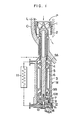
- Fig. 1 shows a pump unit having incorporated therein one embodiment of the invention.
- the pump unit comprises a pump section P, and a motor section M for driving the pump section P.
- the pump section P comprises a main impeller 1 and guide vanes 2, and is located in a fluid passage L defined in a casing C for delivering a fluid in the direction of an arrow or downwardly in the plane of Fig. 1.
- the motor section M which constitutes a wet motor is secured to the casing C as a motor casing 3 is joined to the casing C.
- the motor section M comprises a motor shaft 4, a rotor 5 located on the motor shaft 4, and a stator 6 supported on the motor casing 3 and juxtaposed against the rotor 5.
- the motor shaft 4 has its one end attached to a thrust disc 7 serving concurrently as an auxiliary impeller for circulating motor cooling water and is connected to the main impeller 1 of the pump section P at the other end thereof.
- the thrust disc 7 is formed with a multiplicity of ducts 8 for performing a pumping action.
- the motor shaft 4 is journalled by radial bearings 9A and 9B.
- Thrust bearings l0A and 10B are located in positions in which they are juxtaposed against a front surface of the thrust disc 7 or auxiliary impeller located on its suction side and a rear surface thereof located on its discharge side, respectively.
- the thrust bearings 10A and 10B and thrust disc 7 perform the function of bearing a hydrodynamic thrust load applied by the main impeller 1 and acting upwardly in the plane of Fig. 1. Cooling water pressurized by the thrust disc 7 or auxiliary impeller cools the stator 6 of the motor section M and flows through a heat exchanger 11 located outside the pump unit before returning to the suction side of the thrust disc 7
- a first fine gap defining member 12 cooperating with an outer peripheral surface of the thrust disc 7 for defining a first fine gap G 1 serving as a passage for a back flow of the water discharged by the auxiliary impeller and flowing to its suction side is located on an inner surface of the motor casing 3.
- a second gap defining member 13 extends from the inner surface of the pump casing 3 along an inner peripheral surface of the thrust disc 7 to define therebetween a second fine gap G 2 .
- the first and second fine gap defining members 12 and 13 which are each in the form of a cylinder define a pressure control chamber 14 between the front surface of the thrust disc 7 on its suction side and the inner surface of the pump casing 3.
- the pressure control chamber 14 has its pressure set at a predetermined level by a drop in pressure caused by a loss of pressure by the fluid due to the presence of the first and second fine gaps G 1 and G 2 .
- the pressure in the pressure control chamber 14 acts on the front surface of the thrust disc 7 on its suction side and, combined with the pressure of a fluid acting on the rear surface of the thrust disc 7 on its discharge side, performs the function of reducing the thrust load produced by the main impeller 1.
- Actuation of the motor section M causes the main impeller 1 and the thrust disc 7 serving as an auxiliary impeller to rotate, so that the main impeller 1 delivers a fluid in the passage L downwardly in the plane of Fig. 1 as indicated by the arrow, while the thrust disc 7 functions as an auxiliary impeller to draw cooling water through the suction side as shown in Fig. 2 and discharge same after pressurizing same by the pumping action performed through the ducts 8.
- the major portion of the discharged cooling water flows through the thrust bearing 10B on the rear surface of the thrust disc 7 to cool same and then along an outer periphery of the motor shaft 4, from which it flows further upwardly to cool the stator 6 of the motor section M, before flowing into the heat exchanger 11 located outside the pump unit as shown in Fig. 1.
- the cooling water that has performed cooling is cooled by heat exchange performed in the heat exchanger 11 and returns to the suction side of the thrust disc 7 serving as an auxiliary impeller.
- a pressure P 3 in the pressure control chamber 14 is intermediate between a suction pressure P 1 of the auxiliary impeller and a discharge pressure P 2 thereof due to a loss of pressure in the first and second fine gaps G 1 and G 2 -
- the pressure P 3 can be controlled as desired by arbitrarily setting the dimensions of the first and second fine gaps G 1 and G 2 or their widths and lengths.
- the main impeller 1 usually produces an upwardly directed thrust load W 1 as shown in Fig. 2.
- the load W 1 which is borne by the thrust bearing 10B can be reduced by varying the pressure P 3 in the pressure control chamber 14. More specifically, the pressure P 3 in the pressure control chamber 14 acts on the front surface of the thrust disc 7 and the discharge pressure P 2 of the thrust disc 7 acts on the rear surface of the thrust disc 7.
- the pressure P 3 in the pressure control chamber 14 acts on a level below the discharge pressure P 2 and close to the suction pressure P 1 , it is possible to produce a downwardly directed thrust W 2 at the thrust disc 7 by the relative pressures acting on the front surface and the rear surface of the thrust disc 7.
- the thrust W 2 acts in a direction opposite to the direction in which the thrust load W 1 produced by the main impeller 1 acts, so that it is possible to reduce the thrust load W 1 borne by the thrust bearing 10B. This is conductive to prevention of damage which might otherwise be caused to the thrust bearing 10B, and the service life of the thrust bearing 10B can be prolonged.
- the thrust load W 1 has been assumed to be higher than the thrust W 2 .
- the thrust W 2 might become higher than the thrust load W 1 depending on the conditions under which the main impeller 1 operates.
- the load acting on the thrust bearing 10B would become zero or too small to allow positioning of the motor shaft 4 in the axial direction to be performed stably, thereby causing the motor shaft 4 to vibrate.
- an excessively high load would be applied to the thrust bearing 10A which is designed to have an ability to bear a load substantially of the same level as the weight of a rotary member from the point of view of reducing a mechanical loss, thereby causing damage to the thrust bearing 10A.
- the damage caused to the thrust bearing 10A can be avoided by adjusting the pressure P 3 in the pressure control chamber 14 by varying the dimensions of the first and second fine gaps G 1 and G 2 .
- the pressure P 3 in the pressure control chamber 14 would become equal to the discharge pressure P 2 of the thrust disc 7 if the first fine gap defining member 12 did not exist in Fig. 2, so that no thrust tending to reduce the thrust load W 1 produced by the main impeller 1 would not be produced at the thrust disc 7. Therefore, it would be impossible to reduce the thrust load W 1 unless the first fine gap G 1 is provided.
- the first fine gap G 1 is essential in the present invention to achieve the object of reducing the thrust load W 1 .
- Fig. 3 shows another embodiment, in which the thrust disc 7 serving as an auxiliary impeller is formed with a multiplicity of oblique ducts 8A which are directed obliquely upwardly in going from the center of the thrust disc 7 toward its outer periphery, to enable the length of the first fine gap G 1 to be increased.
- the thrust disc 7 serving as an auxiliary impeller is formed with a multiplicity of oblique ducts 8A which are directed obliquely upwardly in going from the center of the thrust disc 7 toward its outer periphery, to enable the length of the first fine gap G 1 to be increased.
- Fig. 4 shows still another embodiment in which the second fine gap G 2 is modified: As shown, a first cylindrical body 15 extends downwardly from a lower end of the thrust disc 7 in such a manner that inner peripheral surfaces of the first cylindrical body 15 and the thrust disc 7 form a straight line, and a second cylindrical body 16 located outwardly of the first cylindrical body 15 is secured to the motor casing 3.
- the axially extending second fine gap G 2 is defined between an outer peripheral surface of the first cylindrical body 15 and an inner peripheral surface of the second cylindrical member 16 and, at the same time, a first radial fine gap G 21 and a second radial fine gap G 22 are defined between an end face of the first cylindrical body 15 and an inner peripheral surface of the motor casing 3 and between an end face of the second cylindrical body 16 and the lower end of the thrust disc 7, respectively.
- the pumping efficiency of the auxiliary impeller is improved because leaks of the fluid in the pressure control chamber 14 to the suction side of the thrust disc 7 can be minimized by the centrifugal pumping action performed by the end portions of the cylindrical bodies 15 and 16.
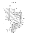
- Fig. 5 shows a further embodiment in which the second fine gap G 2 is further modified.
- a first cylindrical body 17 extends downwardly from a lower end of the thrust disc 7 in such a manner that inner peripheral surfaces of the first cylindrical body 17 and the thrust disc 7 form a straight line
- a second cylindrical body 18 and a third cylindrical body 19 are secured to the motor casing 3 to define a fine gap G 23 between inner and outer peripheral surfaces and an end face of the first cylindrical body 17 and inner peripheral surfaces of the second and third cylindrical bodies 18 and 19.
- the length of the fine gap can be increased and a thrust load of reverse direction produced by the thrust disc 7 can be controlled.
- an increase in the size of the gap prevents the cylindrical body 17 from coming into contact with the cylindrical bodies 18 and 19, and the pumping efficiency of the auxiliary impeller can be improved.
- the present invention enables a thrust load applied to the thrust bearings provided to the thrust disc serving concurrently as an auxiliary impeller to be reduced. This enables a compact size to be obtained in a thrust bearing and allows the service life of the thrust bearings to be prolonged. As a result, the reliability of the pump unit can be greatly increased.
Landscapes
- Engineering & Computer Science (AREA)
- Mechanical Engineering (AREA)
- General Engineering & Computer Science (AREA)
- Physics & Mathematics (AREA)
- Fluid Mechanics (AREA)
- Control Of Non-Positive-Displacement Pumps (AREA)
- Structures Of Non-Positive Displacement Pumps (AREA)
Priority Applications (1)
| Application Number | Priority Date | Filing Date | Title |
|---|---|---|---|
| AT84101200T ATE27341T1 (de) | 1983-03-04 | 1984-02-06 | Axialschubausgleichsvorrichtung fuer pumpen. |
Applications Claiming Priority (2)
| Application Number | Priority Date | Filing Date | Title |
|---|---|---|---|
| JP58034508A JPS59160093A (ja) | 1983-03-04 | 1983-03-04 | サブマ−ジブルポンプの軸スラスト荷重低減装置 |
| JP34508/83 | 1983-03-04 |
Publications (2)
| Publication Number | Publication Date |
|---|---|
| EP0121053A1 true EP0121053A1 (de) | 1984-10-10 |
| EP0121053B1 EP0121053B1 (de) | 1987-05-20 |
Family
ID=12416197
Family Applications (1)
| Application Number | Title | Priority Date | Filing Date |
|---|---|---|---|
| EP84101200A Expired EP0121053B1 (de) | 1983-03-04 | 1984-02-06 | Axialschubausgleichsvorrichtung für Pumpen |
Country Status (4)
| Country | Link |
|---|---|
| EP (1) | EP0121053B1 (de) |
| JP (1) | JPS59160093A (de) |
| AT (1) | ATE27341T1 (de) |
| DE (1) | DE3463824D1 (de) |
Cited By (10)
| Publication number | Priority date | Publication date | Assignee | Title |
|---|---|---|---|---|
| WO1990010161A1 (de) * | 1989-03-04 | 1990-09-07 | Ksb Aktiengesellschaft | Axialschubentlastungseinrichtung |
| US5340272A (en) * | 1992-08-19 | 1994-08-23 | Bw/Ip International, Inc. | Multi-stage centrifugal pump incorporating a sealed thrust bearing |
| US5531564A (en) * | 1994-02-11 | 1996-07-02 | A. Ahlstrom Corporation | Centrifugal pump |
| WO1999041505A1 (en) * | 1998-02-12 | 1999-08-19 | Lemieux Guy B | Integral motor/generator and pump/turbine with hydrostatic bearings |
| WO2007104526A1 (de) * | 2006-03-14 | 2007-09-20 | Ksb Aktiengesellschaft | Kreiselpumpe mit axialschubausgleichseinrichtung |
| US7612143B2 (en) | 1999-08-04 | 2009-11-03 | Hybrid Plastics, Inc. | Metallized nanostructured chemicals alloyed into polymers |
| US7820761B2 (en) | 1999-08-04 | 2010-10-26 | Hybrid Plastics, Inc. | Metallized nanostructured chemicals as cure promoters |
| CN103195745A (zh) * | 2013-04-24 | 2013-07-10 | 东风汽车公司 | 一种新能源汽车的冷却水泵 |
| CN110454509A (zh) * | 2019-08-30 | 2019-11-15 | 福建福清核电有限公司 | 一种唧送型轴承推力盘 |
| CN111998005A (zh) * | 2020-08-25 | 2020-11-27 | 南京工程学院 | 一种水润滑推力轴承的冷却冲洗结构 |
Families Citing this family (4)
| Publication number | Priority date | Publication date | Assignee | Title |
|---|---|---|---|---|
| JPS6389309U (de) * | 1986-11-29 | 1988-06-10 | ||
| JPH088319Y2 (ja) * | 1988-07-18 | 1996-03-06 | 株式会社荏原製作所 | 遠心ポンプのバランスデイスク式軸推力平衡装置 |
| JP4119815B2 (ja) * | 2003-09-30 | 2008-07-16 | 三菱重工業株式会社 | 圧縮機 |
| JP4347173B2 (ja) | 2004-09-15 | 2009-10-21 | 三菱重工業株式会社 | キャンドモーターポンプ |
Citations (5)
| Publication number | Priority date | Publication date | Assignee | Title |
|---|---|---|---|---|
| GB518428A (en) * | 1937-10-06 | 1940-02-27 | Sulzer Ag | Improvements in or relating to rotary immersion pumps |
| DE922807C (de) * | 1945-03-06 | 1955-01-24 | Aeg | Einrichtung zum Ausgleich des Axialschubes mehrstufiger Kreiselpumpen |
| FR1276208A (fr) * | 1960-12-14 | 1961-11-17 | Pompe sans bourrage ni presse-étoupe avec passage du liquide par une section intérieure du palier d'entrée | |
| FR1562733A (de) * | 1967-05-17 | 1969-04-04 | ||
| GB1351826A (en) * | 1971-11-29 | 1974-05-01 | Carter Co J C | Lubricating cooling and balancing of pump and motor units |
Family Cites Families (2)
| Publication number | Priority date | Publication date | Assignee | Title |
|---|---|---|---|---|
| JPS5825876B2 (ja) * | 1980-02-18 | 1983-05-30 | 株式会社日立製作所 | 軸推力平衡装置 |
| JPS5788288A (en) * | 1980-11-21 | 1982-06-02 | Hitachi Ltd | Internal pump |
-
1983
- 1983-03-04 JP JP58034508A patent/JPS59160093A/ja active Granted
-
1984
- 1984-02-06 AT AT84101200T patent/ATE27341T1/de not_active IP Right Cessation
- 1984-02-06 DE DE8484101200T patent/DE3463824D1/de not_active Expired
- 1984-02-06 EP EP84101200A patent/EP0121053B1/de not_active Expired
Patent Citations (5)
| Publication number | Priority date | Publication date | Assignee | Title |
|---|---|---|---|---|
| GB518428A (en) * | 1937-10-06 | 1940-02-27 | Sulzer Ag | Improvements in or relating to rotary immersion pumps |
| DE922807C (de) * | 1945-03-06 | 1955-01-24 | Aeg | Einrichtung zum Ausgleich des Axialschubes mehrstufiger Kreiselpumpen |
| FR1276208A (fr) * | 1960-12-14 | 1961-11-17 | Pompe sans bourrage ni presse-étoupe avec passage du liquide par une section intérieure du palier d'entrée | |
| FR1562733A (de) * | 1967-05-17 | 1969-04-04 | ||
| GB1351826A (en) * | 1971-11-29 | 1974-05-01 | Carter Co J C | Lubricating cooling and balancing of pump and motor units |
Cited By (13)
| Publication number | Priority date | Publication date | Assignee | Title |
|---|---|---|---|---|
| WO1990010161A1 (de) * | 1989-03-04 | 1990-09-07 | Ksb Aktiengesellschaft | Axialschubentlastungseinrichtung |
| US5340272A (en) * | 1992-08-19 | 1994-08-23 | Bw/Ip International, Inc. | Multi-stage centrifugal pump incorporating a sealed thrust bearing |
| US5531564A (en) * | 1994-02-11 | 1996-07-02 | A. Ahlstrom Corporation | Centrifugal pump |
| WO1999041505A1 (en) * | 1998-02-12 | 1999-08-19 | Lemieux Guy B | Integral motor/generator and pump/turbine with hydrostatic bearings |
| US6071091A (en) * | 1998-02-12 | 2000-06-06 | Lemieux; Guy B. | Integral motor/generator and pump/turbine with hydrostatic bearings |
| US7612143B2 (en) | 1999-08-04 | 2009-11-03 | Hybrid Plastics, Inc. | Metallized nanostructured chemicals alloyed into polymers |
| US7820761B2 (en) | 1999-08-04 | 2010-10-26 | Hybrid Plastics, Inc. | Metallized nanostructured chemicals as cure promoters |
| WO2007104526A1 (de) * | 2006-03-14 | 2007-09-20 | Ksb Aktiengesellschaft | Kreiselpumpe mit axialschubausgleichseinrichtung |
| CN103195745A (zh) * | 2013-04-24 | 2013-07-10 | 东风汽车公司 | 一种新能源汽车的冷却水泵 |
| CN103195745B (zh) * | 2013-04-24 | 2015-08-19 | 东风汽车公司 | 一种新能源汽车的冷却水泵 |
| CN110454509A (zh) * | 2019-08-30 | 2019-11-15 | 福建福清核电有限公司 | 一种唧送型轴承推力盘 |
| CN111998005A (zh) * | 2020-08-25 | 2020-11-27 | 南京工程学院 | 一种水润滑推力轴承的冷却冲洗结构 |
| CN111998005B (zh) * | 2020-08-25 | 2022-02-18 | 南京工程学院 | 一种水润滑推力轴承的冷却冲洗结构 |
Also Published As
| Publication number | Publication date |
|---|---|
| ATE27341T1 (de) | 1987-06-15 |
| EP0121053B1 (de) | 1987-05-20 |
| DE3463824D1 (en) | 1987-06-25 |
| JPS626119B2 (de) | 1987-02-09 |
| JPS59160093A (ja) | 1984-09-10 |
Similar Documents
| Publication | Publication Date | Title |
|---|---|---|
| EP0121053B1 (de) | Axialschubausgleichsvorrichtung für Pumpen | |
| US6884043B2 (en) | Fluid circulation path for motor pump | |
| US3790309A (en) | Unitary pump-motor assembly | |
| US5890880A (en) | Sealed motor driven centrifugal fluid pump | |
| US3160108A (en) | Thrust carrying arrangement for fluid handling machines | |
| US6861777B2 (en) | Motor pump with balanced motor rotor | |
| US3016184A (en) | Rotary compressors | |
| US6814549B2 (en) | Liner for fluid pump motor | |
| KR101841117B1 (ko) | 터보 블로워의 모터 냉각구조 | |
| JP3474852B2 (ja) | 超過圧力ガスの生成方法 | |
| US11754086B2 (en) | Bearing housing for a flow machine and a flow machine with a bearing housing | |
| JP2941206B2 (ja) | サブインペラーを備えた循環ポンプ | |
| US2268358A (en) | Centrifugal pump | |
| JP3741092B2 (ja) | 超薄型ポンプとこれを備えた冷却システム | |
| US6554586B1 (en) | Sealed motor driven centrifugal primary fluid pump with secondary fluid flow for cooling primary fluid | |
| GB2036869A (en) | Submersible Motor Pump | |
| US5451147A (en) | Turbo vacuum pump | |
| US3894815A (en) | Bolted hermetic refrigerent gas compressor with electric motor drive | |
| JPS6229675Y2 (de) | ||
| KR20220087633A (ko) | 원심식 터보 압축기 | |
| US3846050A (en) | Centrifugal pumps having rotatable pole rings supported in contactless bearings | |
| EP0883749A1 (de) | Kompressor | |
| KR102738439B1 (ko) | 냉각 기로를 구비한 기체 사이클 히트 펌프 | |
| JP4158269B2 (ja) | 外部駆動形ラインポンプ | |
| JP3256315B2 (ja) | 空気動圧軸受 |
Legal Events
| Date | Code | Title | Description |
|---|---|---|---|
| PUAI | Public reference made under article 153(3) epc to a published international application that has entered the european phase |
Free format text: ORIGINAL CODE: 0009012 |
|
| 17P | Request for examination filed |
Effective date: 19840206 |
|
| AK | Designated contracting states |
Designated state(s): AT DE GB |
|
| GRAA | (expected) grant |
Free format text: ORIGINAL CODE: 0009210 |
|
| AK | Designated contracting states |
Kind code of ref document: B1 Designated state(s): AT DE GB |
|
| REF | Corresponds to: |
Ref document number: 27341 Country of ref document: AT Date of ref document: 19870615 Kind code of ref document: T |
|
| REF | Corresponds to: |
Ref document number: 3463824 Country of ref document: DE Date of ref document: 19870625 |
|
| PLBE | No opposition filed within time limit |
Free format text: ORIGINAL CODE: 0009261 |
|
| STAA | Information on the status of an ep patent application or granted ep patent |
Free format text: STATUS: NO OPPOSITION FILED WITHIN TIME LIMIT |
|
| 26N | No opposition filed | ||
| PGFP | Annual fee paid to national office [announced via postgrant information from national office to epo] |
Ref country code: DE Payment date: 19920429 Year of fee payment: 9 |
|
| PGFP | Annual fee paid to national office [announced via postgrant information from national office to epo] |
Ref country code: AT Payment date: 19921229 Year of fee payment: 10 |
|
| PGFP | Annual fee paid to national office [announced via postgrant information from national office to epo] |
Ref country code: GB Payment date: 19930128 Year of fee payment: 10 |
|
| PG25 | Lapsed in a contracting state [announced via postgrant information from national office to epo] |
Ref country code: DE Effective date: 19931103 |
|
| PG25 | Lapsed in a contracting state [announced via postgrant information from national office to epo] |
Ref country code: GB Effective date: 19940206 Ref country code: AT Effective date: 19940206 |
|
| GBPC | Gb: european patent ceased through non-payment of renewal fee |
Effective date: 19940206 |