EP0121086A2 - Wagon de marchandises ferroviaire - Google Patents
Wagon de marchandises ferroviaire Download PDFInfo
- Publication number
- EP0121086A2 EP0121086A2 EP84102002A EP84102002A EP0121086A2 EP 0121086 A2 EP0121086 A2 EP 0121086A2 EP 84102002 A EP84102002 A EP 84102002A EP 84102002 A EP84102002 A EP 84102002A EP 0121086 A2 EP0121086 A2 EP 0121086A2
- Authority
- EP
- European Patent Office
- Prior art keywords
- hood
- closed position
- end wall
- railway freight
- freight wagon
- Prior art date
- Legal status (The legal status is an assumption and is not a legal conclusion. Google has not performed a legal analysis and makes no representation as to the accuracy of the status listed.)
- Granted
Links
Images


Classifications
-
- B—PERFORMING OPERATIONS; TRANSPORTING
- B61—RAILWAYS
- B61D—BODY DETAILS OR KINDS OF RAILWAY VEHICLES
- B61D39/00—Wagon or like covers; Tarpaulins; Movable or foldable roofs
- B61D39/002—Sliding or folding roofs
- B61D39/003—Sliding or folding roofs telescopic
-
- B—PERFORMING OPERATIONS; TRANSPORTING
- B60—VEHICLES IN GENERAL
- B60J—WINDOWS, WINDSCREENS, NON-FIXED ROOFS, DOORS, OR SIMILAR DEVICES FOR VEHICLES; REMOVABLE EXTERNAL PROTECTIVE COVERINGS SPECIALLY ADAPTED FOR VEHICLES
- B60J7/00—Non-fixed roofs; Roofs with movable panels, e.g. rotary sunroofs
- B60J7/02—Non-fixed roofs; Roofs with movable panels, e.g. rotary sunroofs of sliding type, e.g. comprising guide shoes
- B60J7/04—Non-fixed roofs; Roofs with movable panels, e.g. rotary sunroofs of sliding type, e.g. comprising guide shoes with rigid plate-like element or elements, e.g. open roofs with harmonica-type folding rigid panels
- B60J7/041—Non-fixed roofs; Roofs with movable panels, e.g. rotary sunroofs of sliding type, e.g. comprising guide shoes with rigid plate-like element or elements, e.g. open roofs with harmonica-type folding rigid panels for utility vehicles, e.g. with slidable and foldable rigid panels
Definitions
- the invention relates to a rail freight wagon with end walls and a fixed central portal, a substantially flat loading floor and covering the loading space, lying in the closed position in one plane and sliding over one another on running rails on rollers, which are divided in their upper parting with joints and an elastic crown Provide cover and can be raised and swung out for displacement from its closed position into a displacement position by means of an actuating device.
- a structure covering the loading area consists of at least two hoods lying side by side in the closed position, which are supported by rollers and can be pushed into one another in order to simplify the loading and unloading of the vehicle body in such a way that, depending on the Direction of displacement of these hoods the left or the right hood of the loading area can be completely released.
- the hoods of this known embodiment are longitudinally divided in their upper apex, the two halves of each hood being connected to one another by means of joints.
- separate, parallel rails are provided for the rollers of each hood, on which the hoods can be moved.
- a disadvantage of this known design is the lack of clamping of the hoods with the car body in the closed position of the hoods, so that the longitudinal forces occurring during the movement of the freight wagon from the cargo are fully absorbed as bending forces from the end walls.
- a rail vehicle with extendable and movable hoods is also known, in which the hoods can be formed in their upper apex with a strip of flexible material around which the both hood halves formed by the arrangement of the strip can be pivoted against each other in a predetermined range.
- at least two support rails for two or more hoods are provided in the vicinity of a long side of the loading floor in a plane below the loading surface of the same.
- To move the hoods they are lifted out of their closed position and swiveled out by means of an actuating device and moved over the hood in the closed position.
- both hoods To expose the second half of the cargo space, both hoods must now be moved together over the first half of the cargo space that has already been opened.
- a disadvantage of this known design is also the lack of clinging of the hoods to the vehicle body in the closed position, as well as the complicated design of the actuating device of the individual hoods, which requires several rails on each side of the wagon and sometimes makes it necessary to move several hoods one above the other.
- a railway freight wagon which has a roof and side parts, each of which contains at least two movable wall parts.
- These wall parts are arranged in the closed position on a common plane and can be pivoted by means of an actuating device, for example rotatably mounted guides, into a displacement plane lying in front of the common closure plane and can be displaced in this plane in the longitudinal direction of the vehicle.
- the wall parts are with Roof sections connected, each extending in the length of a wall part and forming the overall vehicle roof. In the case of wall parts located in the plane of displacement, the roof sections have a position which permits longitudinal displacement.
- a disadvantage of this embodiment described above is the multi-joint system of each hood, which includes fundamental disadvantages with regard to the softness of the individual hoods in the closed position and when they are moved. For this reason, this embodiment is not discussed further in the present invention.
- the object of the present invention was to cover the loading space by means of hoods in a railroad freight wagon of the type mentioned at the beginning and to design the hoods and their actuating device in such a way that in the closed position the hoods at least partially transfer the longitudinal forces acting on the end walls to the underframe of the railroad freight wagon, that the actuating device of the hoods ensures an optional displacement of the individual hoods one above the other, that the actuating device is simple and economical, that a reliable function is ensured and that the disadvantages of the aforementioned, known designs are avoided.
- this object is achieved in that the central portal fixedly connected to the underframe is arranged without struts, that each hood covering the loading space between an end wall and the central portal is clamped positively and non-positively to the front wall in the longitudinal position in the closed position at its end wall-side longitudinal end , on their longitudinal sides near the bottom end wall-side longitudinal end with connection sc hl agstucken in direction of the end wall with game stop cam on the frame of the underframe of the railway goods wagon is, Near its central portal-side longitudinal end on its long sides below with cramps in the direction of the end wall with play in front and under anti-locking cams of the underframe, the hood stands above support feet firmly arranged on the long sides at the bottom in support rails of the underframe, and that the hood by means of the actuating device from the closed position with their rollers on the rails in the sliding position can be raised, swung out and set down.
- the hoods covering the loading space can optionally be lifted and moved over the portal and the hood in the closed position.
- the space within the clearance profile can be optimally used for the loading space.
- the hoods In the closed position of the hoods, the hoods are automatically clamped to the end walls and the base in the longitudinal direction of the car. As a result, the charge pressure acting on the end walls in the event of a buffer impact is largely transferred to the underframe of the rail freight car via the hoods.
- the end wall can thus be made lighter and its connection to the base frame can be made simpler.
- the hood stands in the support rails of the underframe using its support feet, which relieves the rollers.
- the hood also has a continuous longitudinal member in the area of the clinging to the end wall, on which ribs extending up to the end profiles of the long sides of each half of the hood are fixedly arranged.
- the arrangement of the side member in the hood in the area of its clamping to the front wall enables direct force transmission from the front wall into a load-bearing component of the hood.
- the rib-shaped bows between the end profiles of the long sides of each half of the hood and the side member ensure a direct transfer of the forces from the side member via the bow into the stop pieces and stop cams of the underframe.
- Each support leg and each support rail are provided with corresponding inclined surfaces running in the longitudinal direction of the carriage, the inclined surfaces of the support rail being positioned from the outside with play in front of the inclined surfaces of the support legs in the closed position of the hoods.
- the inclined surfaces of the support rail and the support feet ensure a central insertion of the hood in the closed position and support the lower longitudinal sides of the hood when the cargo is lying against the hood from the inside without hindering the pivoting of the hood from its closed position into the shifting position.
- Each hood is in the sliding position before its closed position and in the closed position against elastic stops on the end wall.
- these elastic stops position the hood in its displacement position before its closed position and ensure the play between stop pieces and stop cams and between cramps and anti-lift cams after an impact.
- Each hood on its outside in the area of the longitudinal member and the portal on its outside have guide rollers which can be rotated about a vertical axis for guiding the displaced hood laterally.
- the three-hinge design allows the hood to be moved to come into contact with the portal or with the hood in the closed position. Touching the hood to be moved with the central portal or the hood in the closed position is avoided by the guide rollers mentioned.
- each long side of the undercarriage there is a single straight and uninterrupted one that runs the entire length of the carriage Track arranged, with at least two castors on castor feet fixedly arranged on each longitudinal side of each hood, as is known, with a short auxiliary track, which laterally projects beyond the castor foot, being fixedly arranged in the longitudinal direction of the carriage on each castor foot.
- Structurally advantageous and economical is the arrangement of a single running rail on each longitudinal side of the car that serves to move both hoods.
- the rollers of the hoods are advantageously arranged firmly on the hoods and have no movable joint parts and thus components which are susceptible to failure.
- the actuating device for each hood includes an actuating shaft on each longitudinal side of the wagon, which is rotatably supported in the longitudinal direction in the undercarriage, the actuating shaft carrying a fixed support arm for each castor foot, at the free end of which a support roller rotatable in the longitudinal direction of the wagon is arranged, both in The closed position of the hood as well as in the sliding position of the hood rests against the auxiliary rail from below before its closed position, the hood being pivotable from the closed position into the displaced position by means of the actuating shaft via the support arm, the support roller and the auxiliary rail. All movable components of the actuating device are advantageously arranged protected in the undercarriage of the railroad car.
- At least one securing fork is fixedly arranged on the actuating shaft near each support arm, which engages around the auxiliary rail in the closed position of the hood and during its pivoting.
- the securing fork secures the hood in the closed position and when swiveling out of its closed position into the shift position against unintentional lifting of the auxiliary rail from the support roller.
- the actuating shafts of each hood are advantageously connected by a linkage which causes the actuating shafts to rotate in opposite directions.
- a relief spring is interposed in the actuating device of each hood, which can be tensioned by the weight of the hood when it is pivoted into its closed position. The relief spring makes lifting and swiveling the hood much easier. Complicated, time-consuming transmission gears within the actuating device are avoided.
- the invention creates a possibility to open half of the loading space of a railway freight wagon completely, whereby the construction of the hood, as an integrated component of the body of the wagon, has a favorable influence on its construction and is therefore economical.
- the actuating device of the hood is composed of a few, protected and simple components, which ensure that the hood can be pivoted and moved securely.
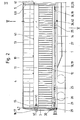
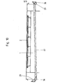
- the loading space of the railway freight wagon shown in the drawing is essentially limited by the loading floor 2 forming the upper side of the underframe 1, the head-end end walls 3 and the two hoods 4.
- a central portal 5 spanning the loading space, which is only attached to the lower frame 1 at the bottom and has no struts in the longitudinal direction of the carriage to the underframe 1 or the end walls 3.
- each hood 4 is divided lengthwise, the halves of each hood 4 being connected to one another in an articulated manner by hinge or bolt joints 9 arranged in the longitudinal axis of the carriage.
- the separation point of each hood 4 is completely covered with an elastic cover 10 which is tightly attached to each half of the hood 4.
- each hood 4 is on each side arranged from end to end longitudinal member 11, from which vertically upward and downward rib-shaped bows 12 emanate, which are firmly connected to horizontally arranged end profiles 13 and 14 at the top and bottom of each half of the hood 4.
- each hood is delimited by the metallic labyrinth seals 6 designed as a profile.
- the hood 4 is covered by means of sheet metal or other suitable means.
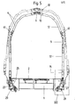
- each hood 4 a hook-shaped bracket 15 is arranged on each side member 11, which rests in the closed position of the hood 4 and in the sliding position of the hood 4 before its closed position against elastic stops 16 of the end wall.
- the clamp 15 includes, with play, a hook 17 arranged on the end wall 3 at the height of the stop 16 sit short support rail 19 which are attached to the base 1.
- Support foot 18 and support rail 19 are arranged in the longitudinal direction of the carriage and are provided with corresponding lateral inclined surfaces running in the longitudinal direction of the carriage, the inclined surfaces of the support rail 19 being positioned in the closed position of the hoods 4 from the outside with play in front of the inclined surfaces of the support feet 18.
- a stop piece 20 is further arranged near the end wall-side longitudinal end thereof, which is in the closed position of the hood 4 with play in front of a stop cam 21 which is arranged on the base frame 1.
- a stop cam 21 which is arranged on the base frame 1.
- Lift-off safety cam 23 stands, which is fixedly arranged on the base frame 1.
- roller barrels 25 are fixedly arranged on each end profile 14 near the longitudinal ends thereof, at the longitudinal ends of which a roller 26 is rotatably arranged.
- the rollers 26 are in the displaced position of the hoods 4 on a running rail 27 which is arranged on the outside of the base frame 1.
- the running rail 27 is straight and continuous from end wall 3 to end wall 3.
- a short auxiliary rail 28, projecting beyond the roller base, is also fixedly arranged in the longitudinal direction of the carriage on each roller base.
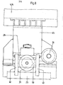
- Each hood 4 is pivoted out of its closed position, in which it rests on the support feet 18 in the support rails 19 of the base frame 1, spread and pivoted outward like a scissors about the pin joint 9, the rollers 26 being placed on the rails 27.
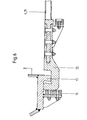
- actuating shafts 29 which are rotatably mounted longitudinally in the base frame.
- At least one handwheel 30 is arranged on the associated end wall 3 for rotating the actuating shaft 29, which rotates a vertical threaded spindle 32 via a gear 31.
- a spindle nut 33 is mounted, on which articulated handlebar rods 34 are arranged, which are articulated at their other end to a lever 35 which is fixedly arranged on the actuating shaft 29.
- the actuating shaft 29 can also be rotated by means of a hydraulic unit. It is also conceivable that the actuating shafts of both hoods are connected via a hydraulic unit that can be operated from an end wall, and thus both hoods can optionally be raised and swung out from an end wall. As shown in Fig. 1 of the drawing, it is also possible to arrange a handwheel 30 on an end wall 3 near each long side of the carriage and to connect the handwheels 30 to one another in a rotationally fixed manner by means of a suitable connecting element.
- the actuating shafts 29 of a hood 4 on each longitudinal side of the carriage are connected to one another via levers 36 arranged fixedly on the actuating shafts and articulated on the handlebars 37 so that the actuating shafts 29 are rotated in opposite directions when the handwheel 30 is rotated.
- a support arm 38 is fixedly arranged on the actuating shaft 29 and carries at its free end a support roller 39 which can be rotated in the longitudinal direction of the carriage.
- the support roller 39 lies with its trough-shaped tread in the closed position of the hood 4 and in the displaced position of the hood 4 before its closed position from below against the auxiliary rail 28.
- the support arm 38 When turning the actuating shaft 29 in ö f f direction of the hood 4, the support arm 38 lifts the support roller 39 and the auxiliary rail 28, the roller foot 25 and with this the hood 4 and pivots this in the shift position.
- securing forks 40 are arranged on the actuating shaft 29 next to the supporting arm 38, which, with their free, fork-shaped end, grip around the auxiliary rail 28 and the auxiliary rail 28 slides from the Prevent support roller 39.
- Suitable and known means such as wheel flanges on the rollers 26 or guide rollers rotatable about vertical axes prevent the rollers 26 from sliding off the slide rail 27 when the hood 4 is displaced.
- 25 clamps are arranged on the roller feet to prevent them from being lifted, which fit into suitable recesses in the Engage the running rail 27 and secure the hood 4 against lifting when moving.
- guide rollers 41 which are rotatable about vertical axes are arranged on the outside of each hood 4 and on the central portal 5.
- a further lever 42 is fixedly arranged, on the free end of which a relief spring 43 is arranged, which is attached at its other end to the underframe 1.
Landscapes
- Engineering & Computer Science (AREA)
- Mechanical Engineering (AREA)
- Transportation (AREA)
- Handcart (AREA)
- Fittings On The Vehicle Exterior For Carrying Loads, And Devices For Holding Or Mounting Articles (AREA)
- Train Traffic Observation, Control, And Security (AREA)
- Forklifts And Lifting Vehicles (AREA)
- Beans For Foods Or Fodder (AREA)
- Body Structure For Vehicles (AREA)
- Loading Or Unloading Of Vehicles (AREA)
- Carriages For Children, Sleds, And Other Hand-Operated Vehicles (AREA)
- Control Of Vehicles With Linear Motors And Vehicles That Are Magnetically Levitated (AREA)
- Drawers Of Furniture (AREA)
- Superstructure Of Vehicle (AREA)
- Platform Screen Doors And Railroad Systems (AREA)
- Refuge Islands, Traffic Blockers, Or Guard Fence (AREA)
Priority Applications (1)
| Application Number | Priority Date | Filing Date | Title |
|---|---|---|---|
| AT84102002T ATE46880T1 (de) | 1983-04-02 | 1984-02-25 | Eisenbahngueterwagen. |
Applications Claiming Priority (2)
| Application Number | Priority Date | Filing Date | Title |
|---|---|---|---|
| DE19833312001 DE3312001A1 (de) | 1983-04-02 | 1983-04-02 | Eisenbahngueterwagen |
| DE3312001 | 1983-04-02 |
Publications (3)
| Publication Number | Publication Date |
|---|---|
| EP0121086A2 true EP0121086A2 (fr) | 1984-10-10 |
| EP0121086A3 EP0121086A3 (en) | 1987-03-11 |
| EP0121086B1 EP0121086B1 (fr) | 1989-10-04 |
Family
ID=6195341
Family Applications (1)
| Application Number | Title | Priority Date | Filing Date |
|---|---|---|---|
| EP84102002A Expired EP0121086B1 (fr) | 1983-04-02 | 1984-02-25 | Wagon de marchandises ferroviaire |
Country Status (15)
| Country | Link |
|---|---|
| US (1) | US4569293A (fr) |
| EP (1) | EP0121086B1 (fr) |
| AT (1) | ATE46880T1 (fr) |
| BR (1) | BR8400953A (fr) |
| CA (1) | CA1217388A (fr) |
| CS (1) | CS276971B6 (fr) |
| DD (1) | DD222250A5 (fr) |
| DE (2) | DE3312001A1 (fr) |
| DK (1) | DK156706C (fr) |
| ES (1) | ES8500154A1 (fr) |
| HU (1) | HU191540B (fr) |
| NO (1) | NO158863C (fr) |
| RO (1) | RO89031A (fr) |
| SU (1) | SU1324581A3 (fr) |
| YU (1) | YU44230B (fr) |
Cited By (5)
| Publication number | Priority date | Publication date | Assignee | Title |
|---|---|---|---|---|
| EP0521695A1 (fr) * | 1991-07-03 | 1993-01-07 | Rautaruukki Oy | Wagon à marchandise avec couverture à capote amovible |
| EP0629537A1 (fr) * | 1993-06-11 | 1994-12-21 | INSTITUT FÜR SCHIENENFAHRZEUGE GmbH | Paroi basculante et coulissante pour wagon de marchandises |
| EP1270361A1 (fr) * | 2001-06-25 | 2003-01-02 | Talgo Oy | Méchanisme inférieur de verrouillage pour paroi coulissante d' un wagon ferroviaire |
| EP2990238A1 (fr) * | 2014-08-29 | 2016-03-02 | European Trailer Systems GmbH | Agencement d'etancheification et superstructure pourvue d'un agencement d'etancheification |
| EP3521128B1 (fr) * | 2018-02-01 | 2021-04-28 | ALSTOM Transport Technologies | Caisse ferroviaire modulaire et véhicule ferroviaire de longueur variable |
Families Citing this family (21)
| Publication number | Priority date | Publication date | Assignee | Title |
|---|---|---|---|---|
| DE3524721A1 (de) * | 1985-07-11 | 1987-01-22 | Talbot Waggonfab | Gedeckter eisenbahngueterwagen |
| DE3527534A1 (de) * | 1985-08-01 | 1987-02-12 | Talbot Waggonfab | Gedeckter eisenbahngueterwagen |
| US4942971A (en) * | 1987-10-10 | 1990-07-24 | Drehtainer Consulting Gmbh | Container |
| DE3823208A1 (de) * | 1988-07-08 | 1990-01-11 | Waggon Union Gmbh | Eisenbahngueterwagen |
| FI81310C (fi) * | 1989-03-09 | 1990-10-10 | Rautaruukki Oy | Jaernvaegsgodsvagn. |
| AT394531B (de) * | 1990-01-19 | 1992-04-27 | Jenbacher Werke Ag | Schienenfahrzeug, insbesondere zweiachsiger gueterwagen |
| US5170717A (en) * | 1990-03-20 | 1992-12-15 | Thrall Car Manufacturing Company | Railroad cars for transporting cylindrical objects transversely with multi-piece movable cover for exposing entire cargo area |
| DE4102041A1 (de) * | 1991-01-24 | 1992-07-30 | Abb Henschel Waggon Union | Eisenbahngueterwagen |
| DE4102476A1 (de) * | 1991-01-29 | 1992-07-30 | Vaw Ver Aluminium Werke Ag | Selbsttragende haube fuer fahrzeuge |
| US5211518A (en) * | 1991-05-24 | 1993-05-18 | Qcx Partners, Inc. | Motor vehicle trailer for hauling steel coils |
| DE4220930A1 (de) * | 1992-06-26 | 1994-01-05 | Abb Henschel Waggon Union | Eisenbahngüterwagen |
| DE4223525A1 (de) * | 1992-07-17 | 1994-01-20 | Abb Henschel Waggon Union | Geschlossener Eisenbahngüterwagen |
| DE4234268C2 (de) * | 1992-10-10 | 1999-05-06 | Deutsche Waggonbau Ag | Ausstelleinrichtung für Schiebewände und Haubenverdecke von Güterwagen |
| DE4239745C2 (de) * | 1992-11-26 | 2002-10-24 | Dwa Deutsche Waggonbau Gmbh | Schienengebundener Haubenwagen |
| DE19914874A1 (de) * | 1999-04-01 | 2000-10-05 | Alstom Lhb Gmbh | Betätigungseinrichtung für eine Schiebewandanordnung eines Eisenbahngüterwagens |
| US6703530B2 (en) * | 2002-02-28 | 2004-03-09 | General Electric Company | Chemical reactor system and process |
| KR100498128B1 (ko) * | 2002-09-17 | 2005-07-01 | 최외수 | 철도용 유개 화차 |
| RU2243917C2 (ru) * | 2002-10-11 | 2005-01-10 | Закрытое акционерное общество "Финтранс" | Железнодорожный грузовой вагон |
| US7445265B1 (en) * | 2007-04-30 | 2008-11-04 | Chameleon Transportation Systems Inc. | Shield assembly for cargo space of a transport vehicle |
| DK178304B1 (en) * | 2014-06-09 | 2015-11-23 | Your Global Solution Aps | A mobile service module, a method for servicing a large mechanical and/or electrical device and use of a mobile service module |
| DE102014012556A1 (de) * | 2014-08-29 | 2016-03-03 | European Trailer Systems Gmbh | Dichtungsanordnung sowie mit einer Dichtungsanordnung versehener Planenaufbau oder Bahnwaggon |
Family Cites Families (9)
| Publication number | Priority date | Publication date | Assignee | Title |
|---|---|---|---|---|
| US1258314A (en) * | 1917-06-12 | 1918-03-05 | John H Bruce | Coal-car cover. |
| US2201737A (en) * | 1939-01-27 | 1940-05-21 | Pennsylvania Railroad Co | Car roof with movable sections |
| FR1451558A (fr) * | 1965-07-23 | 1966-01-07 | D Epluches Atel Const | Véhicule de charge à carrosserie ouvrante |
| US3520257A (en) * | 1967-03-15 | 1970-07-14 | Shunk Mfg Co Inc | Telescopic car covers |
| DE1605008B1 (de) * | 1967-06-03 | 1970-07-23 | Rheinstahl Siegener Eisenbahnb | Vorrichtung zum OEffnen und Schliessen eines Hubschiebedaches,insbesondere an Eisenbahngueterwagen |
| DE2434267B2 (de) * | 1974-07-17 | 1976-09-09 | Waggon Union GmbH, 5902 Netphen | Verriegelung fuer die hauben eines coiltransportwagens |
| DE2832353A1 (de) * | 1978-07-22 | 1980-02-07 | Waggon Union Gmbh | Gedeckter eisenbahngueterwagen |
| US4341163A (en) * | 1980-02-01 | 1982-07-27 | Swiss Aluminium Ltd. | Vehicle superstructure in particular for railway vehicles with hoods which can be expanded outwards and moved with respect to the load bearing platform |
| DE3132002A1 (de) * | 1981-08-13 | 1983-03-03 | Linke-Hofmann-Busch, Waggon-Fahrzeug-Maschinen Gmbh, 3320 Salzgitter | Gedeckter gueterwagen, dessen seitenwaende aus jeweils mindestens zwei beweglichen wandteilen besteht |
-
1983
- 1983-04-02 DE DE19833312001 patent/DE3312001A1/de not_active Withdrawn
-
1984
- 1984-02-15 DK DK069984A patent/DK156706C/da not_active IP Right Cessation
- 1984-02-25 EP EP84102002A patent/EP0121086B1/fr not_active Expired
- 1984-02-25 DE DE8484102002T patent/DE3479993D1/de not_active Expired
- 1984-02-25 AT AT84102002T patent/ATE46880T1/de not_active IP Right Cessation
- 1984-02-29 ES ES530162A patent/ES8500154A1/es not_active Expired
- 1984-02-29 BR BR8400953A patent/BR8400953A/pt not_active IP Right Cessation
- 1984-03-01 CS CS841458A patent/CS276971B6/cs not_active IP Right Cessation
- 1984-03-06 NO NO840844A patent/NO158863C/no unknown
- 1984-03-28 YU YU549/84A patent/YU44230B/xx unknown
- 1984-03-30 RO RO84114128A patent/RO89031A/fr unknown
- 1984-03-30 DD DD84261474A patent/DD222250A5/de not_active IP Right Cessation
- 1984-03-30 US US06/595,332 patent/US4569293A/en not_active Expired - Fee Related
- 1984-04-02 CA CA000451137A patent/CA1217388A/fr not_active Expired
- 1984-04-02 HU HU841314A patent/HU191540B/hu not_active IP Right Cessation
- 1984-04-02 SU SU843717305A patent/SU1324581A3/ru active
Cited By (5)
| Publication number | Priority date | Publication date | Assignee | Title |
|---|---|---|---|---|
| EP0521695A1 (fr) * | 1991-07-03 | 1993-01-07 | Rautaruukki Oy | Wagon à marchandise avec couverture à capote amovible |
| EP0629537A1 (fr) * | 1993-06-11 | 1994-12-21 | INSTITUT FÜR SCHIENENFAHRZEUGE GmbH | Paroi basculante et coulissante pour wagon de marchandises |
| EP1270361A1 (fr) * | 2001-06-25 | 2003-01-02 | Talgo Oy | Méchanisme inférieur de verrouillage pour paroi coulissante d' un wagon ferroviaire |
| EP2990238A1 (fr) * | 2014-08-29 | 2016-03-02 | European Trailer Systems GmbH | Agencement d'etancheification et superstructure pourvue d'un agencement d'etancheification |
| EP3521128B1 (fr) * | 2018-02-01 | 2021-04-28 | ALSTOM Transport Technologies | Caisse ferroviaire modulaire et véhicule ferroviaire de longueur variable |
Also Published As
| Publication number | Publication date |
|---|---|
| YU54984A (en) | 1988-04-30 |
| US4569293A (en) | 1986-02-11 |
| ES530162A0 (es) | 1984-11-01 |
| DK69984D0 (da) | 1984-02-15 |
| SU1324581A3 (ru) | 1987-07-15 |
| CS145884A3 (en) | 1992-04-15 |
| DK156706B (da) | 1989-09-25 |
| ES8500154A1 (es) | 1984-11-01 |
| DE3312001A1 (de) | 1984-10-04 |
| RO89031A (fr) | 1986-03-15 |
| NO158863C (no) | 1988-11-09 |
| EP0121086A3 (en) | 1987-03-11 |
| YU44230B (en) | 1990-04-30 |
| DE3479993D1 (en) | 1989-11-09 |
| CS276971B6 (en) | 1992-11-18 |
| CA1217388A (fr) | 1987-02-03 |
| ATE46880T1 (de) | 1989-10-15 |
| HUT39117A (en) | 1986-08-28 |
| DK156706C (da) | 1990-02-19 |
| BR8400953A (pt) | 1985-02-26 |
| NO158863B (no) | 1988-08-01 |
| HU191540B (en) | 1987-03-30 |
| NO840844L (no) | 1984-10-03 |
| DK69984A (da) | 1984-10-03 |
| EP0121086B1 (fr) | 1989-10-04 |
| DD222250A5 (de) | 1985-05-15 |
Similar Documents
| Publication | Publication Date | Title |
|---|---|---|
| EP0121086B1 (fr) | Wagon de marchandises ferroviaire | |
| EP0349970B1 (fr) | Wagon ferroviaire | |
| DE2003857C3 (de) | Vorrichtung zum Öffnen und Schließen von Schiebetüren eines Fahrzeuges, insbesondere Schienenfahrzeuges | |
| DE1810252A1 (de) | Container | |
| DE3002825C2 (de) | Bodenplatten-Anordnung | |
| DE69200515T2 (de) | Eisenbahnwagen zum Tragen von verriegelbaren Ladungssätteln und Ladungssattel für ein solchen Wagen. | |
| DE60033900T2 (de) | Führung für eine bewegliche Abdeckung und bewegliche Abdeckung unter Verwendung einer solchen Führung | |
| DE1964814C3 (de) | Schiebewand für Fahrzeuge, insbesondere Eisenbahngüterwagen | |
| DE9108115U1 (de) | Zusammenschiebbares Verdeck für Fahrzeuge oder Fahrzeugaufbauten | |
| DE1605032C3 (de) | Gedeckter Güterwagen mit im geschlossenen Zustand in einer Ebene liegenden Schiebewandteilen | |
| EP0579150B1 (fr) | Wagon de merchandises fermé | |
| DE1755253C3 (de) | Vorrichtung zum Festlegen fahrbarer Behälter auf einer Fahrzeugladefläche, insbesondere auf der Ladefläche eines Eisenbahnwagens | |
| WO1992012881A1 (fr) | Wagon a marchandises | |
| EP0855980A1 (fr) | Systeme de parois coulissantes | |
| DE3323655C2 (fr) | ||
| DE4420796C1 (de) | Verriegelung zwischen einem Drehrahmen und einem Container | |
| DE2103985C3 (de) | Schiebewandanordnung für gedeckte Eisenbahngüterwagen und Container | |
| DE2315116A1 (de) | Vorrichtung zum einstellen und festklemmen von eisenbahnwaggons in einem drehentlader | |
| DE2155851C3 (de) | Seitenwand, insbesondere für Eisenbahngüterwagen, mit verschiebbaren Wandteilen | |
| DE2910799A1 (de) | Fahrzeugkoerper, insbesondere fuer schienenfahrzeuge mit ausstellbaren und verschiebbaren hauben | |
| DE4042181A1 (de) | Uebergangsbruecke fuer schienenfahrzeuge | |
| DD261053A3 (de) | Spreizhaubenverdeck fuer gueterwagen und container | |
| DE1274156B (de) | Gedeckter Eisenbahngueterwagen, dessen Seitenwaende aus je zwei in geschlossenem Zustand in einer Ebene liegenden Schiebewandteilen bestehen | |
| DE2459777A1 (de) | Schiebewandanordnung fuer gedeckte eisenbahngueterwagen | |
| DE2103985A1 (de) | Schiebewandanordnung für gedeckte Eisenbahngüterwagen und Container |
Legal Events
| Date | Code | Title | Description |
|---|---|---|---|
| PUAI | Public reference made under article 153(3) epc to a published international application that has entered the european phase |
Free format text: ORIGINAL CODE: 0009012 |
|
| 17P | Request for examination filed |
Effective date: 19840312 |
|
| AK | Designated contracting states |
Designated state(s): AT BE CH DE FR GB IT LI NL SE |
|
| PUAL | Search report despatched |
Free format text: ORIGINAL CODE: 0009013 |
|
| RHK1 | Main classification (correction) |
Ipc: B61D 39/00 |
|
| AK | Designated contracting states |
Kind code of ref document: A3 Designated state(s): AT BE CH DE FR GB IT LI NL SE |
|
| 17Q | First examination report despatched |
Effective date: 19881109 |
|
| GRAA | (expected) grant |
Free format text: ORIGINAL CODE: 0009210 |
|
| AK | Designated contracting states |
Kind code of ref document: B1 Designated state(s): AT BE CH DE FR GB IT LI NL SE |
|
| REF | Corresponds to: |
Ref document number: 46880 Country of ref document: AT Date of ref document: 19891015 Kind code of ref document: T |
|
| GBT | Gb: translation of ep patent filed (gb section 77(6)(a)/1977) | ||
| REF | Corresponds to: |
Ref document number: 3479993 Country of ref document: DE Date of ref document: 19891109 |
|
| ITF | It: translation for a ep patent filed | ||
| ET | Fr: translation filed | ||
| PLBE | No opposition filed within time limit |
Free format text: ORIGINAL CODE: 0009261 |
|
| STAA | Information on the status of an ep patent application or granted ep patent |
Free format text: STATUS: NO OPPOSITION FILED WITHIN TIME LIMIT |
|
| 26N | No opposition filed | ||
| ITTA | It: last paid annual fee | ||
| PGFP | Annual fee paid to national office [announced via postgrant information from national office to epo] |
Ref country code: SE Payment date: 19921214 Year of fee payment: 10 |
|
| PGFP | Annual fee paid to national office [announced via postgrant information from national office to epo] |
Ref country code: NL Payment date: 19930228 Year of fee payment: 10 |
|
| PGFP | Annual fee paid to national office [announced via postgrant information from national office to epo] |
Ref country code: BE Payment date: 19931203 Year of fee payment: 11 |
|
| PG25 | Lapsed in a contracting state [announced via postgrant information from national office to epo] |
Ref country code: SE Effective date: 19940226 |
|
| PG25 | Lapsed in a contracting state [announced via postgrant information from national office to epo] |
Ref country code: NL Effective date: 19940901 |
|
| NLV4 | Nl: lapsed or anulled due to non-payment of the annual fee | ||
| EUG | Se: european patent has lapsed |
Ref document number: 84102002.7 Effective date: 19940910 |
|
| PG25 | Lapsed in a contracting state [announced via postgrant information from national office to epo] |
Ref country code: BE Effective date: 19950228 |
|
| BERE | Be: lapsed |
Owner name: WAGGON UNION G.M.B.H. Effective date: 19950228 |
|
| PGFP | Annual fee paid to national office [announced via postgrant information from national office to epo] |
Ref country code: FR Payment date: 19971217 Year of fee payment: 15 |
|
| PG25 | Lapsed in a contracting state [announced via postgrant information from national office to epo] |
Ref country code: FR Free format text: LAPSE BECAUSE OF NON-PAYMENT OF DUE FEES Effective date: 19991029 |
|
| REG | Reference to a national code |
Ref country code: FR Ref legal event code: ST |
|
| PGFP | Annual fee paid to national office [announced via postgrant information from national office to epo] |
Ref country code: GB Payment date: 20000207 Year of fee payment: 17 |
|
| PGFP | Annual fee paid to national office [announced via postgrant information from national office to epo] |
Ref country code: AT Payment date: 20000218 Year of fee payment: 17 |
|
| PGFP | Annual fee paid to national office [announced via postgrant information from national office to epo] |
Ref country code: CH Payment date: 20000228 Year of fee payment: 17 |
|
| PGFP | Annual fee paid to national office [announced via postgrant information from national office to epo] |
Ref country code: DE Payment date: 20000313 Year of fee payment: 17 |
|
| PG25 | Lapsed in a contracting state [announced via postgrant information from national office to epo] |
Ref country code: GB Free format text: LAPSE BECAUSE OF NON-PAYMENT OF DUE FEES Effective date: 20010225 Ref country code: AT Free format text: LAPSE BECAUSE OF NON-PAYMENT OF DUE FEES Effective date: 20010225 |
|
| PG25 | Lapsed in a contracting state [announced via postgrant information from national office to epo] |
Ref country code: LI Free format text: LAPSE BECAUSE OF NON-PAYMENT OF DUE FEES Effective date: 20010228 Ref country code: CH Free format text: LAPSE BECAUSE OF NON-PAYMENT OF DUE FEES Effective date: 20010228 |
|
| REG | Reference to a national code |
Ref country code: CH Ref legal event code: PL |
|
| GBPC | Gb: european patent ceased through non-payment of renewal fee |
Effective date: 20010225 |
|
| PG25 | Lapsed in a contracting state [announced via postgrant information from national office to epo] |
Ref country code: DE Free format text: LAPSE BECAUSE OF NON-PAYMENT OF DUE FEES Effective date: 20011201 |