EP0121122B1 - Serre-câble à ruban - Google Patents
Serre-câble à ruban Download PDFInfo
- Publication number
- EP0121122B1 EP0121122B1 EP84102300A EP84102300A EP0121122B1 EP 0121122 B1 EP0121122 B1 EP 0121122B1 EP 84102300 A EP84102300 A EP 84102300A EP 84102300 A EP84102300 A EP 84102300A EP 0121122 B1 EP0121122 B1 EP 0121122B1
- Authority
- EP
- European Patent Office
- Prior art keywords
- cable tie
- cable
- eye
- wire
- tie according
- Prior art date
- Legal status (The legal status is an assumption and is not a legal conclusion. Google has not performed a legal analysis and makes no representation as to the accuracy of the status listed.)
- Expired
Links
- 239000004033 plastic Substances 0.000 claims abstract description 29
- 229920003023 plastic Polymers 0.000 claims abstract description 29
- 239000004020 conductor Substances 0.000 claims abstract description 3
- 239000000463 material Substances 0.000 claims abstract 6
- 238000003780 insertion Methods 0.000 claims description 4
- 230000037431 insertion Effects 0.000 claims description 4
- 238000004873 anchoring Methods 0.000 claims 6
- 210000004279 orbit Anatomy 0.000 claims 1
- 239000002184 metal Substances 0.000 description 7
- 230000035882 stress Effects 0.000 description 5
- 206010063493 Premature ageing Diseases 0.000 description 3
- 208000032038 Premature aging Diseases 0.000 description 3
- 238000002347 injection Methods 0.000 description 3
- 239000007924 injection Substances 0.000 description 3
- 239000011248 coating agent Substances 0.000 description 2
- 238000000576 coating method Methods 0.000 description 2
- 230000007797 corrosion Effects 0.000 description 2
- 238000005260 corrosion Methods 0.000 description 2
- 238000009413 insulation Methods 0.000 description 2
- WABPQHHGFIMREM-UHFFFAOYSA-N lead(0) Chemical compound [Pb] WABPQHHGFIMREM-UHFFFAOYSA-N 0.000 description 2
- 238000004519 manufacturing process Methods 0.000 description 2
- 239000000853 adhesive Substances 0.000 description 1
- 230000001070 adhesive effect Effects 0.000 description 1
- 238000005452 bending Methods 0.000 description 1
- 238000005336 cracking Methods 0.000 description 1
- 230000000694 effects Effects 0.000 description 1
- 239000003292 glue Substances 0.000 description 1
- 238000007654 immersion Methods 0.000 description 1
- 238000000034 method Methods 0.000 description 1
- 238000012986 modification Methods 0.000 description 1
- 230000004048 modification Effects 0.000 description 1
- 238000003825 pressing Methods 0.000 description 1
- 230000005855 radiation Effects 0.000 description 1
- 239000007921 spray Substances 0.000 description 1
- 238000003860 storage Methods 0.000 description 1
- 239000000725 suspension Substances 0.000 description 1
- 229920001169 thermoplastic Polymers 0.000 description 1
- 239000004416 thermosoftening plastic Substances 0.000 description 1
- 239000002699 waste material Substances 0.000 description 1
Images
Classifications
-
- F—MECHANICAL ENGINEERING; LIGHTING; HEATING; WEAPONS; BLASTING
- F16—ENGINEERING ELEMENTS AND UNITS; GENERAL MEASURES FOR PRODUCING AND MAINTAINING EFFECTIVE FUNCTIONING OF MACHINES OR INSTALLATIONS; THERMAL INSULATION IN GENERAL
- F16L—PIPES; JOINTS OR FITTINGS FOR PIPES; SUPPORTS FOR PIPES, CABLES OR PROTECTIVE TUBING; MEANS FOR THERMAL INSULATION IN GENERAL
- F16L3/00—Supports for pipes, cables or protective tubing, e.g. hangers, holders, clamps, cleats, clips, brackets
-
- G—PHYSICS
- G02—OPTICS
- G02B—OPTICAL ELEMENTS, SYSTEMS OR APPARATUS
- G02B6/00—Light guides; Structural details of arrangements comprising light guides and other optical elements, e.g. couplings
- G02B6/46—Processes or apparatus adapted for installing or repairing optical fibres or optical cables
- G02B6/47—Installation in buildings
- G02B6/475—Mechanical aspects of installing cables in ducts or the like for buildings
Definitions
- the invention relates to a cable band clamp made of plastic with a flexible metal insert, which has at one end an eyelet for pushing through the other end, in particular for the attachment of cables, lines, pipes or the like to tension cables.
- band clamps To fasten cables or the like to tensioning cables carrying them, it is known to use insulating tape clamps to prevent the risk of carryover of voltage that may occur in the case of live cables and lines, while such band clamps are mostly used for reasons of hanging pipes corrosion-free.
- the band clamps made of plastic have continuous teeth and a locking tongue located within their eyelet (DE-A-29 19 144). The band clamp is looped around the tensioning cable and the cable or pipe, then the free end of the band is inserted through the eyelet and finally the band is drawn in, the locking tongue holding the looped band under tension and preventing it from pulling up automatically.
- thermoplastic used for such cable band clamps begins to flow, whereby the clamp initially loosens, the band loop becomes loose, but the weight of the cable maintains a certain tension in it. It leads to stress corrosion cracking and thus to premature aging and ultimately to the breaking of the band clamp. With short-lived products and when using such clamps indoors, this premature aging does not have a particularly disadvantageous effect. It is different, however, if such insulating tape clamps are used outdoors and also under extreme temperature and weather conditions. Then, under the influence of temperature changes and in particular also under the influence of UV radiation, such plastic cable band clamps age comparatively quickly and, depending on the load, break very quickly. But you just have to use cable fastenings used outdoors, such as. B.
- the invention is therefore based on the object to provide a cable clamp made of a flexible metal insert plastic, which is simple and inexpensive to manufacture and is designed so that its plastic sheathing is subject to much less stress, so is much more protected and thereby the band clamp has a much longer lifespan.
- This object is achieved on the basis of a cable band clamp of the type mentioned in the invention in that the band clamp consists of plastic-coated round wire which is bent into a U-shaped part at its apex with bent-in, closely adjacent legs which are firmly connected to one another .
- the round metallic support body used namely the round wire, creates the conditions for ensuring that its plastic sheathing is rounded, i.e. free of sharp edges and local overstressing, and therefore also adheres much better to the metal wire without stress cracks and corresponding corrosion damage.
- the new cable band clamp can also be manufactured very easily, in particular if, for this purpose, an appropriately U-shaped, insulated conductor wire is used, the adjacent legs of which have simply been glued to one another or have been welded by application of heat.
- the cable band clamp can also consist of round wire, which is first bent and cranked in a U-shape and only then coated with plastic. In all cases the band clamps produced in this way can be used their adhering wire legs and their free ends simply looped through the top of the U-shape eyelet and then tightened.
- the cable band clamp can also consist of several nested, appropriately shaped, plastic-coated round wires, which are firmly connected to each other by their adjacent legs. In this way, correspondingly higher load capacities can be achieved, as is sometimes necessary, for example, for attaching heavy cables, lines or pipes to tension cables.
- the cable band clamp is provided with a closure head receiving its eyelet, which is provided with a correspondingly rounded, lateral recess forming the eyelet receptacle, which merges into an elongated threading channel receiving the legs of the band clamp and in its base has a push-through window for the band clamp end to be inserted through the latter and the eyelet.
- This locking head ensures that the eyelet remains dimensionally stable when the strap loop is closed, so the latter cannot open automatically.
- a resilient clamping tongue is provided in the bottom of the recess of the closure head, which projects into the push-through window and points in the push-through direction of the free band clamp end.
- closure head has a fork-like clamping mouth at its end opposite the threading channel for the free band clamp end to be inserted through the push-through window and the eyelet and to be retracted by 180 °.
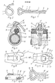
- the cable band clamp shown in Figures 1 and 2 consists of the flexible metallic round wire 2 provided with an insulating plastic sheath 1, which is bent into the flat-lying U-shape shown in Figure 1, which forms the push-through eye 3 in its apex, while the two Legs 4, 4 'of the U-shape are bent inwards, lie close together and are firmly connected to one another at the interface 5.
- Conventional electrical lead wire is advantageously used for the cable band clamp shown, possibly even corresponding wire waste material, the wire being cut to a suitable length on a relatively simple machine and bent into the U-shape shown in FIG. 1.
- the legs 4, 4 ' are welded together at the longitudinal contact point 5.
- the cable band clamp can be effortlessly brought from its flat, stretched position shown in FIG. 1 into the loop shape shown in FIG. 2, as is necessary for fastening lighter cables or lines.
- the band clamp is placed around the tensioning or carrying rope and the line to be fastened to it, with its free end 6 inserted through the eyelet 3 and then bent back to prevent the fastening loop thus formed from being pulled open.
- the cable band clamp is used together with the closure head 7 shown in FIGS. 5 to 7.
- This is provided with a correspondingly rounded, lateral recess 8 for receiving the band clamp eyelet 3, which merges into an elongated threading channel 9 receiving the wire legs 4, 4 'of the band clamp and has a push-through window 10 in its base 8' for the latter and the eyelet 3 has a free band clamp end 6 to be inserted.
- the closure head 7 has a fork-shaped Ktemmau) 11 for the free band clamp end 6 to be passed through the push-through window 10 and the eyelet 3 and to be bent back by 180 °.
- his fork jaws 11 ' are provided with bevels 11 ".
- a resilient clamping tongue 12 which projects into the push-through window 10 and points in the push-through direction of the free band clamp end 6 and which, as it were, allows the band clamp to be steplessly locked in its closed loop shape.
- the closure head 7 consists of Spray plastic and can be easily manufactured. For its shape it is remarkable that the side recess 8, the push-through window 10, the threading channel 9 and the Kfemmau! 11 are contoured so that you can get by with a simple two-part injection mold for the manufacture of the closure head.
- FIGS. 1 and 2 the practical application of the provided with a locking head 7 new cable clamp is shown, so it is a question of attaching the cable 13 to the tensioning or suspension cable 14 at several suitable spaced locations by means of the cable clamp .
- the wire loop shown in FIGS. 1 and 2 is first brought together with the closure head 7, the wire loop with its band end 6 being passed from the lateral recess 8 through the threading channel 9 until the eyelet 3 or it forming wire loop in the recess 8 Flatz finds.
- the cable clamp can also consist of several nested, correspondingly U-shaped, plastic-coated round wires 15, 16, which are firmly connected to each other via their adjoining legs 15 ', 16', i.e. also are either welded or glued together.
- the multi-wire band clamp is advantageously used in conjunction with a correspondingly designed closure head 7 which, apart from its dimensions, can be of basically the same shape as the closure head shown in FIGS. 5 to 7.
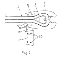
- FIG. 9 Another embodiment of the closure head 7 is shown in FIG. 9.
- the threading channel 9 ' is open at the top.
- the channel 9 ' is covered by the clamping plate 17.
- the clamping plate 17 can be designed as a loose item or, as shown e.g. be connected to the closure head 7 via a flexible web 18.
- insertion holes 19 and correspondingly designed clamping pins 20 can be provided on the closure head 7 and 17 on the clamping plate.
- the pins 20 can equally well be arranged on the closure head 7 and the clamping openings 19 in the clamping plate 17. Any other suitable clamp or snap connection can also be used for this, as is customary when plastic injection molded parts are inserted into one another.
- the cable band clamp can basically also consist of initially bare round wire 2, which is therefore in uninsulated form and is first bent in a U-shaped manner in order to then coat it with plastic, be it in an appropriate injection mold or by immersion .
- wire legs of the round wire can in principle also lie directly next to one another, it is nevertheless advisable to keep them at a suitable distance in front of the plastic overlay, so that in this case as well as possible a plastic sheath is formed that is free of sharp-edged areas and associated local areas Overuse is.
Landscapes
- Engineering & Computer Science (AREA)
- Civil Engineering (AREA)
- Structural Engineering (AREA)
- Physics & Mathematics (AREA)
- General Engineering & Computer Science (AREA)
- General Physics & Mathematics (AREA)
- Optics & Photonics (AREA)
- Mechanical Engineering (AREA)
- Clamps And Clips (AREA)
- Cable Accessories (AREA)
Claims (11)
Priority Applications (1)
| Application Number | Priority Date | Filing Date | Title |
|---|---|---|---|
| AT84102300T ATE27347T1 (de) | 1983-03-08 | 1984-03-03 | Kabelbandschelle. |
Applications Claiming Priority (2)
| Application Number | Priority Date | Filing Date | Title |
|---|---|---|---|
| DE3308136 | 1983-03-08 | ||
| DE3308136A DE3308136C2 (de) | 1983-03-08 | 1983-03-08 | Kabelbandschelle |
Publications (3)
| Publication Number | Publication Date |
|---|---|
| EP0121122A2 EP0121122A2 (fr) | 1984-10-10 |
| EP0121122A3 EP0121122A3 (en) | 1984-11-14 |
| EP0121122B1 true EP0121122B1 (fr) | 1987-05-20 |
Family
ID=6192822
Family Applications (1)
| Application Number | Title | Priority Date | Filing Date |
|---|---|---|---|
| EP84102300A Expired EP0121122B1 (fr) | 1983-03-08 | 1984-03-03 | Serre-câble à ruban |
Country Status (3)
| Country | Link |
|---|---|
| EP (1) | EP0121122B1 (fr) |
| AT (1) | ATE27347T1 (fr) |
| DE (2) | DE3308136C2 (fr) |
Cited By (1)
| Publication number | Priority date | Publication date | Assignee | Title |
|---|---|---|---|---|
| CZ301892B6 (cs) * | 2006-04-04 | 2010-07-21 | Benda@Milan | Príchytka, zejména elektrických rozvodu ke zdi |
Families Citing this family (1)
| Publication number | Priority date | Publication date | Assignee | Title |
|---|---|---|---|---|
| FR2777713B1 (fr) * | 1998-04-20 | 2002-12-06 | Frederic Jacquet | Dispositif d'attache elastique reutilisable |
Family Cites Families (7)
| Publication number | Priority date | Publication date | Assignee | Title |
|---|---|---|---|---|
| US953394A (en) * | 1907-01-02 | 1910-03-29 | W G Nagel Electric Company | Cable-hanger. |
| US1455612A (en) * | 1921-06-08 | 1923-05-15 | Charles M Heeter | Pipe grip |
| US2001917A (en) * | 1933-01-04 | 1935-05-21 | Utilities Service Company Inc | Strain device |
| AT180784B (de) * | 1953-05-21 | 1955-01-10 | Garvenswerke Maschinen Pumpen & Waagenfabrik W Garvens | Schellenartiges Verbindungsmittel |
| FR1287586A (fr) * | 1961-02-03 | 1962-03-16 | Collier à vis | |
| DE1903587A1 (de) * | 1969-01-24 | 1970-11-12 | Leppak Gmbh Vkg W | Aufhaengevorrichtung |
| US4183119A (en) * | 1978-05-15 | 1980-01-15 | Dennison Manufacturing Company | Harnessing device with gripper rails |
-
1983
- 1983-03-08 DE DE3308136A patent/DE3308136C2/de not_active Expired
-
1984
- 1984-03-03 EP EP84102300A patent/EP0121122B1/fr not_active Expired
- 1984-03-03 DE DE8484102300T patent/DE3463834D1/de not_active Expired
- 1984-03-03 AT AT84102300T patent/ATE27347T1/de not_active IP Right Cessation
Cited By (1)
| Publication number | Priority date | Publication date | Assignee | Title |
|---|---|---|---|---|
| CZ301892B6 (cs) * | 2006-04-04 | 2010-07-21 | Benda@Milan | Príchytka, zejména elektrických rozvodu ke zdi |
Also Published As
| Publication number | Publication date |
|---|---|
| EP0121122A3 (en) | 1984-11-14 |
| ATE27347T1 (de) | 1987-06-15 |
| EP0121122A2 (fr) | 1984-10-10 |
| DE3463834D1 (en) | 1987-06-25 |
| DE3308136C2 (de) | 1985-05-23 |
| DE3308136A1 (de) | 1984-10-04 |
Similar Documents
| Publication | Publication Date | Title |
|---|---|---|
| DE1966107A1 (de) | Kabelbinder | |
| DE102010012249B3 (de) | Seil- und Litzenverbinder | |
| DE2802586C3 (de) | Halter zum Abspannen isolierter, elektrischer Versorgungsleitungen | |
| DE1955961B2 (de) | Kabelbefestigung | |
| DE2112237C3 (de) | Spiralarmatur zur Befestigung einer elektrischen Freileitung an einem Stützisolator | |
| EP0285699B1 (fr) | Pince pour déplacer du matériel flexible sous forme de cordes | |
| DE1912219C3 (de) | Aus schraubenförmig vorgeformten Drähten bestehendes Halteelement zum Befestigen von elektrischen Leitungen auf Isolatoren | |
| DE2946257A1 (de) | Klemme zum befestigen eines endes eines elektrischen kabels an einer unterstuetzungsplatte | |
| DE4430770B4 (de) | Messfühler zur einfachen Befestigung an einem Rohr | |
| EP0335890B1 (fr) | Prise electrique pour jonctions de cables, notamment pour canalisations de cables | |
| DE10302555B3 (de) | Erweiter- und/oder aufhängbarer Kabelschlauch, bestehend aus mindestens einem Kabelschlauchelement | |
| DE3308136C2 (de) | Kabelbandschelle | |
| DE7321597U (de) | Festhalteeinrichtung | |
| DE2647804C2 (de) | Eine Schleife bildendes Spannband | |
| DE202010003259U1 (de) | Befestigungssystem zur Halterung von Kabeln und Schläuchen an einem Träger | |
| DE2133340A1 (de) | Spannbuegel | |
| DE8807139U1 (de) | Befestigungselement aus Kunststoff | |
| DE2031605C3 (de) | Abspannklemme | |
| DE2901249C2 (de) | Leistenförmige Halterung | |
| WO2000070382A1 (fr) | Ligne de transport de courant h.t. comportant un cable optique monte sur un cable conducteur ou de garde | |
| DE60319308T2 (de) | Rohrschelle | |
| DE29823136U1 (de) | Verriegelungsschloß für ein Spannband zum Bündeln langgestreckter Gegenstände, wie Kabelbündel, Wellrohre u.dgl. | |
| DE2834078A1 (de) | Vorrichtung zum verbinden der enden zweier rohre o.dgl. | |
| EP0300210A1 (fr) | Fixation de tuyau | |
| DE1926820C (de) | Klammer |
Legal Events
| Date | Code | Title | Description |
|---|---|---|---|
| PUAI | Public reference made under article 153(3) epc to a published international application that has entered the european phase |
Free format text: ORIGINAL CODE: 0009012 |
|
| PUAL | Search report despatched |
Free format text: ORIGINAL CODE: 0009013 |
|
| AK | Designated contracting states |
Designated state(s): AT BE CH DE FR GB IT LI LU NL SE |
|
| AK | Designated contracting states |
Designated state(s): AT BE CH DE FR GB IT LI LU NL SE |
|
| 17P | Request for examination filed |
Effective date: 19850506 |
|
| 17Q | First examination report despatched |
Effective date: 19861002 |
|
| GRAA | (expected) grant |
Free format text: ORIGINAL CODE: 0009210 |
|
| AK | Designated contracting states |
Kind code of ref document: B1 Designated state(s): AT BE CH DE FR GB IT LI LU NL SE |
|
| PG25 | Lapsed in a contracting state [announced via postgrant information from national office to epo] |
Ref country code: NL Effective date: 19870520 Ref country code: IT Free format text: LAPSE BECAUSE OF FAILURE TO SUBMIT A TRANSLATION OF THE DESCRIPTION OR TO PAY THE FEE WITHIN THE PRESCRIBED TIME-LIMIT;WARNING: LAPSES OF ITALIAN PATENTS WITH EFFECTIVE DATE BEFORE 2007 MAY HAVE OCCURRED AT ANY TIME BEFORE 2007. THE CORRECT EFFECTIVE DATE MAY BE DIFFERENT FROM THE ONE RECORDED. Effective date: 19870520 Ref country code: FR Free format text: THE PATENT HAS BEEN ANNULLED BY A DECISION OF A NATIONAL AUTHORITY Effective date: 19870520 Ref country code: BE Effective date: 19870520 |
|
| REF | Corresponds to: |
Ref document number: 27347 Country of ref document: AT Date of ref document: 19870615 Kind code of ref document: T |
|
| PG25 | Lapsed in a contracting state [announced via postgrant information from national office to epo] |
Ref country code: SE Effective date: 19870531 |
|
| REF | Corresponds to: |
Ref document number: 3463834 Country of ref document: DE Date of ref document: 19870625 |
|
| EN | Fr: translation not filed | ||
| NLV1 | Nl: lapsed or annulled due to failure to fulfill the requirements of art. 29p and 29m of the patents act | ||
| PG25 | Lapsed in a contracting state [announced via postgrant information from national office to epo] |
Ref country code: AT Effective date: 19880303 |
|
| PLBE | No opposition filed within time limit |
Free format text: ORIGINAL CODE: 0009261 |
|
| STAA | Information on the status of an ep patent application or granted ep patent |
Free format text: STATUS: NO OPPOSITION FILED WITHIN TIME LIMIT |
|
| PG25 | Lapsed in a contracting state [announced via postgrant information from national office to epo] |
Ref country code: LU Free format text: LAPSE BECAUSE OF NON-PAYMENT OF DUE FEES Effective date: 19880331 Ref country code: LI Effective date: 19880331 Ref country code: CH Effective date: 19880331 |
|
| 26N | No opposition filed | ||
| GBPC | Gb: european patent ceased through non-payment of renewal fee | ||
| PG25 | Lapsed in a contracting state [announced via postgrant information from national office to epo] |
Ref country code: GB Free format text: LAPSE BECAUSE OF NON-PAYMENT OF DUE FEES Effective date: 19881122 |
|
| REG | Reference to a national code |
Ref country code: CH Ref legal event code: PL |
|
| PG25 | Lapsed in a contracting state [announced via postgrant information from national office to epo] |
Ref country code: DE Effective date: 19881201 |