EP0121219A2 - Hangriff - Google Patents
Hangriff Download PDFInfo
- Publication number
- EP0121219A2 EP0121219A2 EP84103380A EP84103380A EP0121219A2 EP 0121219 A2 EP0121219 A2 EP 0121219A2 EP 84103380 A EP84103380 A EP 84103380A EP 84103380 A EP84103380 A EP 84103380A EP 0121219 A2 EP0121219 A2 EP 0121219A2
- Authority
- EP
- European Patent Office
- Prior art keywords
- head
- elements
- handle
- adapter
- stem
- Prior art date
- Legal status (The legal status is an assumption and is not a legal conclusion. Google has not performed a legal analysis and makes no representation as to the accuracy of the status listed.)
- Withdrawn
Links
Images

Classifications
-
- F—MECHANICAL ENGINEERING; LIGHTING; HEATING; WEAPONS; BLASTING
- F16—ENGINEERING ELEMENTS AND UNITS; GENERAL MEASURES FOR PRODUCING AND MAINTAINING EFFECTIVE FUNCTIONING OF MACHINES OR INSTALLATIONS; THERMAL INSULATION IN GENERAL
- F16K—VALVES; TAPS; COCKS; ACTUATING-FLOATS; DEVICES FOR VENTING OR AERATING
- F16K31/00—Actuating devices; Operating means; Releasing devices
- F16K31/44—Mechanical actuating means
- F16K31/60—Handles
-
- F—MECHANICAL ENGINEERING; LIGHTING; HEATING; WEAPONS; BLASTING
- F16—ENGINEERING ELEMENTS AND UNITS; GENERAL MEASURES FOR PRODUCING AND MAINTAINING EFFECTIVE FUNCTIONING OF MACHINES OR INSTALLATIONS; THERMAL INSULATION IN GENERAL
- F16B—DEVICES FOR FASTENING OR SECURING CONSTRUCTIONAL ELEMENTS OR MACHINE PARTS TOGETHER, e.g. NAILS, BOLTS, CIRCLIPS, CLAMPS, CLIPS OR WEDGES; JOINTS OR JOINTING
- F16B2200/00—Constructional details of connections not covered for in other groups of this subclass
- F16B2200/40—Clamping arrangements where clamping parts are received in recesses of elements to be connected
- F16B2200/403—Threaded clamping parts
-
- Y—GENERAL TAGGING OF NEW TECHNOLOGICAL DEVELOPMENTS; GENERAL TAGGING OF CROSS-SECTIONAL TECHNOLOGIES SPANNING OVER SEVERAL SECTIONS OF THE IPC; TECHNICAL SUBJECTS COVERED BY FORMER USPC CROSS-REFERENCE ART COLLECTIONS [XRACs] AND DIGESTS
- Y10—TECHNICAL SUBJECTS COVERED BY FORMER USPC
- Y10T—TECHNICAL SUBJECTS COVERED BY FORMER US CLASSIFICATION
- Y10T403/00—Joints and connections
- Y10T403/70—Interfitted members
- Y10T403/7005—Lugged member, rotary engagement
-
- Y—GENERAL TAGGING OF NEW TECHNOLOGICAL DEVELOPMENTS; GENERAL TAGGING OF CROSS-SECTIONAL TECHNOLOGIES SPANNING OVER SEVERAL SECTIONS OF THE IPC; TECHNICAL SUBJECTS COVERED BY FORMER USPC CROSS-REFERENCE ART COLLECTIONS [XRACs] AND DIGESTS
- Y10—TECHNICAL SUBJECTS COVERED BY FORMER USPC
- Y10T—TECHNICAL SUBJECTS COVERED BY FORMER US CLASSIFICATION
- Y10T74/00—Machine element or mechanism
- Y10T74/20—Control lever and linkage systems
- Y10T74/20576—Elements
- Y10T74/20732—Handles
- Y10T74/20762—Shaft connections
-
- Y—GENERAL TAGGING OF NEW TECHNOLOGICAL DEVELOPMENTS; GENERAL TAGGING OF CROSS-SECTIONAL TECHNOLOGIES SPANNING OVER SEVERAL SECTIONS OF THE IPC; TECHNICAL SUBJECTS COVERED BY FORMER USPC CROSS-REFERENCE ART COLLECTIONS [XRACs] AND DIGESTS
- Y10—TECHNICAL SUBJECTS COVERED BY FORMER USPC
- Y10T—TECHNICAL SUBJECTS COVERED BY FORMER US CLASSIFICATION
- Y10T74/00—Machine element or mechanism
- Y10T74/20—Control lever and linkage systems
- Y10T74/20576—Elements
- Y10T74/20732—Handles
- Y10T74/20834—Hand wheels
- Y10T74/2084—Knob or dial
Definitions
- the present invention relates to decorative handles which are attachable to rotatable stems. It is especially useful in allowing a decorative handle to be attached to a rotatable valve control stem without requiring the use of an exposed access hole or an exposed screw hole.
- Valve control stems are often provided with a fluted attachment end that is formed with an axial screw hole.
- Conventional handles that are designed for use with such stems usually have a fluted interior bore which mates with and slides over the fluted end.
- An attachment screw then passes through the handle and into the stem screw hole to secure the handle to the stem.
- an access hole is normally formed in the top of the handle.
- U.S. Patent No. 4,306,468 disclosed an improved decorative handle assembly which relied upon a sandwiching of an assembly ring and a handle insert around a stem adapter (the stem adapter being screwed onto the stem). While this handle assembly did have advantages over the prior art, it was desired to reduce the cost of manufacture and installation still further.
- the object of the present invention is to provide a concealed mounting arrangement for attaching a handle to a rotatable stem and in which the handle may be attached to stem without requiring the use of a screw hole or other attachment mechanism passing through the handle exterior.
- the present invention porovides the mounting arrangement of claim 1, characterized by said adapter element having a radial flange provided with said slot, said slot extending circumferentially and between a surface of the flange that faces towards a stem free end direction, andanother surface of the flange that faces in the oppositedirection; said handle ele-Dent having said pin thereon, said pin extending towards the flanqe.
- the invention provides an improved means for attaching a decorative handle to a stem.
- the assembly is comprised of few parts, is solid in construction, is inexpensive to manufacture and install, and prevents contaminants from entering the internal handle parts.
- the handle may be readily removed for inspection, cleaning and repair.
- FIG. 1 there is shown a lavatory top 10 through which a valve 11 protrudes. (Only the upper part of the valve 11 is shown.) Threads 12 on the valve 11 carry a threaded attachment nut 13. Nut 13 holds the fixture against upward movement relative to the lavatory top 10.
- a conventional form of valve stem 14 protrudes upwardly from the housing neck 15. It is fluted at its free end 16.
- a threaded axial screw hole 17 is provided in the top of the stem 14, and an escutcheon 19 having inner threads 20 is screwed down upon the valve 11 to sandwich the lavatory top 10.
- the general arrangement of these parts is a common form of construction.
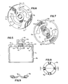
- the adapter 21 has a radial flange 22 which is provided with a pair of kidney shaped circumferential mounting slots 23. Mounting slots 23 extend between a surface 24 of the flange 22 that faces in the stem free end direction (upward) and another surface 25 of the flange 22 that faces in the opposite direction (downward).
- Each slot 23 comprises an enlarged access portion 26, a narrowed intermediate portion 27, and an enlarged pocket 28 adjacent the opposite end of the intermediate portion 27.
- the pocket 28 opens away from the stem free end direction when the adapter 21 is mounted on the stem 14.
- the enlarged access portion 26 is preferably of a uniform diameter all the way through the flange 22.
- the pocket 28 comprises an inner or upper bore 31, and an outer or lower bore 32.
- the outer bore 32 is of a larger diameter than the inner bore 31.
- a fluted central bore 33 which is suitable to receive and mesh with the fluted free end 16 of the stem 14.
- a screw hole 35 is provided in the top of the adapter 21.
- the adapter 21 is mountable on the stem 14 by use of a screw 37 which passes through the screw hole 35 and into the stem hole 17. The adapter 21 and stem 14 will then rotate as a unit, and will be axially fixed relative to each other.
- Handle 38 is removably mountable on the adapter 21. It has two mounting pins or screws 39 which extend towards the flange 22, and which are provided near their outer end with an enlarged head 40. Where screws are used (as in Fig. 1), they can easily be assembled into threaded holes 42 formed in the bottom of the handle by simply turning the screws 39 into the screw holes 42. Instead of screws, rivets and rivet bores can also be used. Other similar configurations (e.g. hooks) may also prove suitable.
- bore 43 in the bottom of the handle 38 is sized so as to slideably fit over adapter hub 44. This allows relative axial and rotational movement between the handle 38 and the adapter 21 when the handle is mounted on the adapter 21.
- Heads 40 of the pins 39 are received through the access portions 26 of the adapter 21. Then, the handle 38 can be rotated with respect to the adapter 21 to a position in which the heads 40 are aligned under the flange with the pockets 28. Relative axial separation of the handle 38 and the adapter 21 will then cause the heads 40 to move upwards into the pockets 28, thereby preventing further rotation of the handle38 with .respect to'the adapter 21.
- An axially compressible washer spring 45 is also provided (see Figures 8-9). It is circular with a central bore 46 of a size that fits around the adapter hub 37. The spring 45 fits between the handle 38 and the adapter 21 so as to provide an upward force on the handle 38. This biases the heads 40 into the pockets 28.
- the assembled handle functions in a manner comparable to conventional faucet handles. Rotation of the handle 38 will cause the adapter 21 and thus the valve stem 14 to turn. This allows the valve to be turned on and off. However, simple rotation in either direction will not lead to the handle becoming disassembled from the adapter or stem.
- skirts 47 and 48 which are formed on the handle and adapter, hide and protect the internal components of the assembled handle.
- the costs of installing the valve are very small.
Landscapes
- Engineering & Computer Science (AREA)
- General Engineering & Computer Science (AREA)
- Mechanical Engineering (AREA)
- Mechanically-Actuated Valves (AREA)
- Snaps, Bayonet Connections, Set Pins, And Snap Rings (AREA)
- Preventing Unauthorised Actuation Of Valves (AREA)
- Mechanical Control Devices (AREA)
Applications Claiming Priority (2)
| Application Number | Priority Date | Filing Date | Title |
|---|---|---|---|
| US06/481,576 US4515037A (en) | 1983-04-01 | 1983-04-01 | Handle assembly |
| US481576 | 1983-04-01 |
Publications (2)
| Publication Number | Publication Date |
|---|---|
| EP0121219A2 true EP0121219A2 (de) | 1984-10-10 |
| EP0121219A3 EP0121219A3 (de) | 1985-03-13 |
Family
ID=23912507
Family Applications (1)
| Application Number | Title | Priority Date | Filing Date |
|---|---|---|---|
| EP84103380A Withdrawn EP0121219A3 (de) | 1983-04-01 | 1984-03-27 | Hangriff |
Country Status (6)
| Country | Link |
|---|---|
| US (1) | US4515037A (de) |
| EP (1) | EP0121219A3 (de) |
| JP (1) | JPS59183184A (de) |
| KR (1) | KR840008484A (de) |
| ES (1) | ES8503447A1 (de) |
| GB (1) | GB2137311A (de) |
Cited By (3)
| Publication number | Priority date | Publication date | Assignee | Title |
|---|---|---|---|---|
| WO1990004125A1 (de) * | 1988-10-10 | 1990-04-19 | Ideal-Standard Gmbh | Betätigungsgriff für sanitäre wasserventile |
| EP0506215A3 (en) * | 1991-03-28 | 1992-12-09 | Oras Oy | Valve stem length adjustment device |
| EP2218950A1 (de) * | 2009-02-12 | 2010-08-18 | Kohler Co. | Griffanordnung |
Families Citing this family (25)
| Publication number | Priority date | Publication date | Assignee | Title |
|---|---|---|---|---|
| US4757786A (en) * | 1985-10-24 | 1988-07-19 | Ellegard Sidney W | Releasable engine coupling arrangement |
| US4860423A (en) * | 1986-08-18 | 1989-08-29 | General Motors Corporation | Method of mounting and regulating a vehicle opening device utilizing a winder |
| US4858489A (en) * | 1986-08-18 | 1989-08-22 | General Motors Corporation | Vehicle window regulator retractable winder apparatus and method |
| US4929111A (en) * | 1987-03-02 | 1990-05-29 | Giuseppe Lauritano | Tool manipulating harmonic balancer |
| US4773788A (en) * | 1987-05-26 | 1988-09-27 | Kadem Tech. Associates, Ltd. | Safety strap assembly for molds and die cast dies |
| US4920824A (en) * | 1988-06-09 | 1990-05-01 | Pom Incorporated | Slip clutch handle for parking meter system |
| US4881631A (en) * | 1988-06-09 | 1989-11-21 | Pom Incorporated | Breakover handle for parking meter |
| US4961443A (en) * | 1989-12-12 | 1990-10-09 | Kohler Co. | Handle assembly |
| US5575757A (en) * | 1992-10-09 | 1996-11-19 | Smith & Nephew Endoscopy Inc. | Endoscope with focusing mechanism |
| US5511286A (en) * | 1992-10-29 | 1996-04-30 | Fmc Corporation | Handle with modular hub |
| USD365009S (en) | 1993-02-25 | 1995-12-12 | Tour & Andersson Ab | Handle |
| US5797422A (en) * | 1996-12-20 | 1998-08-25 | Masco Corporation Of Indiana | Faucet handle assembly |
| US6237440B1 (en) * | 1999-05-13 | 2001-05-29 | Joshua Lebelo | Locking device for faucet |
| GB0103860D0 (en) * | 2001-02-16 | 2001-04-04 | Heavenor Glen | Improved knob |
| US6438771B1 (en) | 2001-03-09 | 2002-08-27 | Moen Incorporated | Faucet handle mechanism |
| US7225828B2 (en) * | 2005-03-21 | 2007-06-05 | Giagni Jr Vincent | Decorative faucet assembly formed of plastic figurine molded onto metal parts |
| CN101223399B (zh) * | 2005-06-09 | 2012-04-18 | 山田明 | 通路块的结合装置 |
| USD602124S1 (en) | 2009-03-26 | 2009-10-13 | Danco, Inc. | Sillcock handle |
| US9303391B2 (en) | 2010-09-16 | 2016-04-05 | Kohler Co. | Faucet mount assembly |
| US9259744B2 (en) | 2011-04-22 | 2016-02-16 | Kohler Co. | Faucet |
| USD657654S1 (en) * | 2011-06-29 | 2012-04-17 | Mitutoyo Corporation | Knob for a stand for measuring instruments |
| US10494834B2 (en) | 2012-10-29 | 2019-12-03 | Robert J Schrader | Decorative door handle and hinge |
| USD805971S1 (en) * | 2014-03-24 | 2017-12-26 | Denso International America, Inc. | Haptic control knob |
| US10436343B2 (en) | 2017-12-08 | 2019-10-08 | Delta Faucet Company | Valve assembly including magnetic handle retention with spring assist |
| US10689835B2 (en) | 2018-03-01 | 2020-06-23 | Delta Faucet Company | Spring adjustable handle for faucet valve assembly |
Family Cites Families (14)
| Publication number | Priority date | Publication date | Assignee | Title |
|---|---|---|---|---|
| US1690801A (en) * | 1923-05-14 | 1928-11-06 | Racine Electric Company | Clipper |
| US1524764A (en) * | 1924-08-21 | 1925-02-03 | Wilmot Castle Co | Handle for valves, shafts, or the like |
| US2039917A (en) * | 1935-07-24 | 1936-05-05 | Michel Harold | Means for attaching a handle to a stem or the like |
| US2117759A (en) * | 1936-04-04 | 1938-05-17 | Kingston Products Corp | Electric lighting device |
| US2726570A (en) * | 1949-10-06 | 1955-12-13 | American Optical Corp | Optical diagnostic instruments |
| US2759754A (en) * | 1955-02-08 | 1956-08-21 | Kaiser Fred | Knob assembly for mortised door latch |
| US3572162A (en) * | 1969-04-01 | 1971-03-23 | Vsi Corp | Plumbing handle knob combination |
| GB1561972A (en) * | 1976-08-09 | 1980-03-05 | Turnock Ltd George | Knobs |
| US4065216A (en) * | 1976-09-17 | 1977-12-27 | Zin-Plas Corporation | Adjustable faucet handle assembly |
| AT353070B (de) * | 1977-10-17 | 1979-10-25 | Schmiedl Gustav | Handgriff fuer ein betaetigungsorgan, insbesondere fuer ein ventil od.dgl. einer sanitaeren armatur |
| GB1599531A (en) * | 1978-03-30 | 1981-10-07 | Armitage Shanks Group Ltd | Water taps and control valves |
| US4306468A (en) * | 1979-09-04 | 1981-12-22 | Kohler Co. | Handle assembly |
| US4385577A (en) * | 1981-08-03 | 1983-05-31 | The Singer Company | Sewing machine control mechanism mounting plate |
| DE8135257U1 (de) * | 1981-12-03 | 1982-04-22 | Christophery Gmbh, 5860 Iserlohn | Ventiloberteil mit drehgriff |
-
1983
- 1983-04-01 US US06/481,576 patent/US4515037A/en not_active Expired - Fee Related
-
1984
- 1984-03-23 GB GB08407628A patent/GB2137311A/en not_active Withdrawn
- 1984-03-27 EP EP84103380A patent/EP0121219A3/de not_active Withdrawn
- 1984-03-30 ES ES531130A patent/ES8503447A1/es not_active Expired
- 1984-03-30 KR KR1019840001661A patent/KR840008484A/ko not_active Withdrawn
- 1984-03-30 JP JP59063113A patent/JPS59183184A/ja active Pending
Cited By (5)
| Publication number | Priority date | Publication date | Assignee | Title |
|---|---|---|---|---|
| WO1990004125A1 (de) * | 1988-10-10 | 1990-04-19 | Ideal-Standard Gmbh | Betätigungsgriff für sanitäre wasserventile |
| EP0506215A3 (en) * | 1991-03-28 | 1992-12-09 | Oras Oy | Valve stem length adjustment device |
| EP2218950A1 (de) * | 2009-02-12 | 2010-08-18 | Kohler Co. | Griffanordnung |
| US8079381B2 (en) | 2009-02-12 | 2011-12-20 | Kohler Co. | Handle assembly for a water control valve |
| CN101852306B (zh) * | 2009-02-12 | 2012-12-12 | 科勒公司 | 手柄组件 |
Also Published As
| Publication number | Publication date |
|---|---|
| JPS59183184A (ja) | 1984-10-18 |
| GB2137311A (en) | 1984-10-03 |
| KR840008484A (ko) | 1984-12-15 |
| ES531130A0 (es) | 1985-02-16 |
| EP0121219A3 (de) | 1985-03-13 |
| ES8503447A1 (es) | 1985-02-16 |
| GB8407628D0 (en) | 1984-05-02 |
| US4515037A (en) | 1985-05-07 |
Similar Documents
| Publication | Publication Date | Title |
|---|---|---|
| EP0121219A2 (de) | Hangriff | |
| US4961443A (en) | Handle assembly | |
| US6438771B1 (en) | Faucet handle mechanism | |
| US4616673A (en) | Replacement faucet handle kit | |
| CA2004267C (en) | Hanger with improved positioning structure | |
| US6725472B2 (en) | Combined faucet and drain assembly | |
| US5865211A (en) | Faucet installation aid | |
| US4876766A (en) | Decorative faucet handle mounting apparatus | |
| KR970007817B1 (ko) | 장식용 핸들 조립체 | |
| US6066119A (en) | Waste water strainer and valve | |
| CA1130772A (en) | Handle assembly | |
| US4565350A (en) | Handle assembly | |
| JPH02240464A (ja) | 衛生器具用混合弁 | |
| US5316355A (en) | Integral door knob assembly with spring return | |
| RU2144636C1 (ru) | Узел ручки смесителя водопроводного крана | |
| CA2059516C (en) | Faucet handle assembly | |
| US5142740A (en) | Toilet covering hinge assembly | |
| DK155549B (da) | Forbindelsesindretning til indbyrdes forbindelse af armene paa et et-grebs blandingsbatteri | |
| EP0324366A1 (de) | Bedienungsvorrichtung oder dgl. | |
| US2967728A (en) | Door handle construction | |
| US4998321A (en) | Handle assembly | |
| PL183608B1 (pl) | Zespół uchwytu do drzwi | |
| US20250154752A1 (en) | Faucet with interchangeable handle | |
| US5318263A (en) | Wall-mount rod for hand shower | |
| CA2371473A1 (en) | Single handle lavatory faucet with handle collar for seating valve assembly |
Legal Events
| Date | Code | Title | Description |
|---|---|---|---|
| PUAI | Public reference made under article 153(3) epc to a published international application that has entered the european phase |
Free format text: ORIGINAL CODE: 0009012 |
|
| AK | Designated contracting states |
Designated state(s): DE FR GB IT |
|
| PUAL | Search report despatched |
Free format text: ORIGINAL CODE: 0009013 |
|
| AK | Designated contracting states |
Designated state(s): DE FR GB IT |
|
| STAA | Information on the status of an ep patent application or granted ep patent |
Free format text: STATUS: THE APPLICATION IS DEEMED TO BE WITHDRAWN |
|
| 18D | Application deemed to be withdrawn |
Effective date: 19851114 |
|
| RIN1 | Information on inventor provided before grant (corrected) |
Inventor name: BLOCK, DALE A. |