EP0121293A1 - Système de parole numérique à phrase programmable - Google Patents
Système de parole numérique à phrase programmable Download PDFInfo
- Publication number
- EP0121293A1 EP0121293A1 EP84300315A EP84300315A EP0121293A1 EP 0121293 A1 EP0121293 A1 EP 0121293A1 EP 84300315 A EP84300315 A EP 84300315A EP 84300315 A EP84300315 A EP 84300315A EP 0121293 A1 EP0121293 A1 EP 0121293A1
- Authority
- EP
- European Patent Office
- Prior art keywords
- speech
- memory
- data
- computer
- processor
- Prior art date
- Legal status (The legal status is an assumption and is not a legal conclusion. Google has not performed a legal analysis and makes no representation as to the accuracy of the status listed.)
- Withdrawn
Links
Images








Classifications
-
- G—PHYSICS
- G06—COMPUTING OR CALCULATING; COUNTING
- G06F—ELECTRIC DIGITAL DATA PROCESSING
- G06F3/00—Input arrangements for transferring data to be processed into a form capable of being handled by the computer; Output arrangements for transferring data from processing unit to output unit, e.g. interface arrangements
- G06F3/16—Sound input; Sound output
Definitions
- This invention relates to interactive computer systems, and more particularly to such systems capable of communicating with an operator by transforming digitally encoded speech data segments into understandable speech.
- the invention is relevant to the field of computer-assisted instruction.
- Digital speech processors that can operate in parallel with a programmable digital computer have come into widespread use in recent years.
- An excellent example is the "solid State Speech"(trademark) synthesizer that is widely used as an accessory for the Texas Instruments TI99/4A home computer.
- This synthesizer can accept from the computer a stream of data that defines the individual phonemes of a spoken message and that must be presented to the synthesizer at a controlled rate of speed, with relatively continuous active involvement of the computer in the speech generation process.
- a read-only memory (12X and 12A in FIG. 2 of the patent) containing a plurality of variable length, digitally-encoded speech data segments is connected to a synthesizer that is connected in turn to a computer.
- the computer can initiate the conversion of an entire single data segment into speech by passing the address of the segment to the read-only memory and by then starting the synthesizer. In this manner, a single speech segment may be generated in response to a single request from the computer, with no further computer intervention.
- a primary object of the present invention is producing a computer-controlled digital speech system that can be programmed in advance by a computer to generate an entire speech message containing an arbitrarily-arranged sequence of spoken phrases, each derived from separate and non-consecutively-stored, variable-length, digitally-encoded speech data segments.
- Another object of the invention is to permit such a digital speech system to be programmed to include silent passages of arbitrary length at scattered points within the spoken phrases without intervention of the computer.
- a further object of the invention is to simplify as much as possible the task of programming the speech system to reduce the time it takes to produce computer-aided instructional exercises and to reduce the complexity of coordinating speech -generation with other activities (graphics, music, etc.) carried out by an instructional computer.
- Still another object is to provide a speech synthesizer system having a speech and command memory with means for accessing the memory by the personal computer during its periods of nonuse as a speech synthesizer.
- the present invention constitutes the combination of a programmable digital computer and a digital speech processor.
- a speech memory that contains variable-length, digitally-encoded speech data segments.
- a command memory wherein variable-length sequences of compact commands may be stored, each command calling either for the production of speech through the processing of one of the digitally-encoded speech segments or for the production of a silent or non-speech interval of a specified time duration.
- Both the speech memory and the command memory are random- access memories that the digital computer may load with speech data and command data.
- the command data is compact and may be altered rapidly by the computer.
- the computer may quickly program the speech processor to produce any arbitrary sequence of the corresponding speech intermixed with pauses. And while the speech processor is producing the speech, the computer is completely free to attend to other tasks, such as the production of a matching set of video images, animations, text written upon the face of the computer's display screen, music, and the like. There is no need for the computer to be interrupted by the speech processor at the end of. every phrase to generate a pause or to instruct the speech processor of what phrase is to be generated next.
- the speech memory is also programmable, so the computer may periodically load into the speech memory an entirely new set of messages.
- the computer could even accept typed responses from the user (for example, the name of the child who is receiving instruction), convert those typed letter responses into corresponding speech data, load the speech data into the speech memory along with other words and phrases, and then program the speech processor to produce a verbal reply to the user that contains the spoken rendition of the user's response (e.g.: the child's name spoken to him or her as part of a response).
- the invention greatly simplifies the task of creating a computer-aided instructional program by permitting the author of such a program to separate the task of speech generation from all the other tasks.
- the author can create a speech command data sequence that includes the entire verbal portion of the instructional frame, optionally including short pauses between phrases and a much longer pause followed by a sequence of time-spaced encouragement prompts at times when a student response is required.
- the author may then focus all of the computer's resources upon animation, graphics, and other such tasks without any concern about speech.
- Each variable-length speech data segment may be thought of as a phrase-generating subroutine executable by the speech processor.
- the speech processor also contains a delay subroutine that generates time delays.
- the computer When the computer feeds speech data segments into the speech processor, it is programming the speech data processor with specific phrase generating subroutines. Then when the computer produces a speech command sequence, the computer is writing a computer program that contains an arbitrary sequence of subroutine calls to the phrase generating subroutines intermixed with subroutine calls to the time delay generating subroutine within the speech processor. The computer feeds this speech command sequence program to the speech processor and then calls for its execution at the appropriate time.
- the speech processor and the speech data and command data memories are mounted upon a card that may be inserted into a slot in the peripheral connector of the programmable computer, with leads extending to an external audio amplifier and speaker.
- the speech processor may thus be plugged quickly and simply into the programmable computer.
- the speech processor further includes first and second data conveyance means connecting the computer to the speech memory for writing to and reading from the memory, respectively.
- the computer When programmed to use the speech synthesis mode, the computer will enable a control line which initiates the parallel operation of the microcomputer by starting its control programs. In this mode speech synthesis will take place in parallel with other of the computers operations such as graphics or the like. Otherwise, the computer will in an auxiliary-mode use the speech memory as a portion of its memory space to be written into or read from as desired. If the computer will be using the speech synthesis mode, then the speech memory is loaded with command data and speech data to be operated on by the microcomputer. If the spech memory is to be used for auxiliary memory space then the computer can load whatever data needs to be stored therein.
- the speech memory is extremely well adapted for list or file processing.
- One use of the speech processor memory in the auxiliary mode would be to receive files as they were read off a hard or floppy disc and to store them in the sequence read. Thereafter, by setting up a table of pointers to the starting address of the files, each file can be read individually by the personal computer for data manipulation and processing.
- FIG 1 presents an overview block diagram of a digital speech system 100 designed in accordance with the present invention.
- the system 100 includes a programmable digital computer 102. While many types of computers can be used in implementing the invention, the Apple II+ computer manufactured by Apple Computer, Incorporated, was selected for use in constructing the preferred embodiment of the invention because of its suitability for use in computer-aided instruction, its relatively low cost, and its present popularity among educators.
- the computer 102 typically would include a keyboard and a display monitor (not shown).
- peripheral connector 106 includes eight Winchester #2HW25CO-111 50 pin printed circuit card edge connectors, the wiring of which are described on pages 105 to 109 of the book "Apple II Reference Manual", published by Apple Computer, Incorporated in 1979. Hence, eight accessories may be connected to the Apple II+ peripheral connectors.
- Other compact programmable digital computers provide equivalent peripheral connectors or equivalent connector means for enabling accessories to exchange information with them.
- the present invention contemplates connecting a speech processor 200 to the computer 102 by means of the peripheral connector 106.
- the speech processor 200 generates an output signal AUDIO 602 that is fed into an audio system 600 where the signal is filtered and amplified and fed to a speaker 604, which may be a loudspeaker as shown or a set of headphones, the headphones being possibly more appropriate for use in a classroom setting.
- the speech processor 200 and some or all of the audio system 600 can be mounted on a printed circuit board that plugs into the peripheral connector 106.
- the computer 102 can then be adapted for speech use by the simple act of inserting the speech processor 200 into a slot in the peripheral connector 106, leaving part or all of the audio system 600 and speaker 604 in a separate housing external to the computer.
- the insertion of the speech processor 200 into a slot in the peripheral connector 106 additionally provides access to the 64K of memory stored thereon. Since the speech processor is connected to the data, address, and control bus of the computer 102 via the connector 106, the memory of the board when not being used for speech processing is adapted. to become an extension of the memory space available to the user.
- the program set of the computer 102 is augmented by the addition of a speech control program 104.
- the program 104 may take many different forms, and it may simply be part of a computer-aided instructional program that also performs many other tasks, such as monitoring keystrokes, writing letters, numbers, symbols, and colors on a display monitor, accessing data and programs stored on external memory files, and the like. But whatever its form and main function, the program 104 includes the necessary commands, instructions, and subroutines to communicate with the speech processor 200 and to cause speech to flow from the loudspeaker 604.
- an exemplary program 104 is described which is used to demonstrate the operation of the speech processor 200 with a human typing in hexadecimal numbers to initiate the production of corresponding elements of speech.
- the program 104 disclosed herein thus simulates how the system would function if a computer aided instructional exercise were supplying the hexadecimal numbers calling for the generation of speech rather than a human.
- FIGS. 2 through 8 of the drawings are partly block diagrams, partly logic diagrams, and partly circuit diagrams.
- a signal is either a "normal” signal or an "inverted” signal.
- the names of signals are capitalized. If a signal name is overlined in the drawings and if a signal enters logic gates through a circle, then the signal is inverted. Inverted signals are “present” when at ground potential and “absent” when positive. If a signal name is not overlined and if a signal does not enter logic gates through a circle, then the signal is normal. Normal signals are “present” when positive and “absent” when at ground potential. Since the inverted or normal nature of a signal is apparent in the drawings, no mention of the normal or inverted state of a signal is normally made in this description.
- Logic elements shaped like a letter “D” are control gates that "enable” the flow of one signal only if all the other signals entering the same gate are “present.”
- Logic elements shaped like bullets or arrows are signal combining gates that permit any input signal to flow through the gate to its output.
- Triangular gates (for example, the gate 208 in FIG. 2) simply invert a signal from normal to inverted or vice versa, and these gates are frequently not even mentioned in the description that follows, since their function is made clear in the drawings.
- the speech processor 200 is presented.
- a microcomputer 202 which generates the control signals that control the operation of the speech processor 200.
- the microcomputer 202 is a Rockwell International Corporation R6500/1 Microcomputer System, the details of which are described in the publication dated June 1979, entitled “Document No. 29650-N48: R6500 Microcomputer System PRODUCT DESCRIPTION R 6501/1 ONE-CHIP MICROCOMPUTER", published by Rockwell International Corporation.
- the Processor 200 also contains a speech memory 214 which is a 64K byte random access memory device constructed from up to eight 64K bit dynamic random access memory units No. TMS4164 manufactured by Texas Instruments, Incorporated.
- the processor contains a voice synthesizer 216 Model TMS 5220 also manufactured by Texas Instruments Incorporated.
- the voice synthesizer 216 is fully described in the Texas Instruments publication DM-02 dated June 1981 and entitled "TMS 5220 Voice Synthesis Processor Data Manual.”
- the speech memory 214 if the speech processing mode is to be used, is first loaded with speech data by the computer 102.
- the memory 214 has the capacity to hold about five minutes worth of speech which may be broken up into up to 608 discrete speech segments.
- the computer 102 first generates the necessary peripheral connector 106 signals to cause the bus input logic 300 to generate a count signal 217. This signal 217 resets the 8-bit counter 218 to zero count and also passes through a gate 206 and resets the 8-bit counter 220 to zero count.
- the outputs 222 and 224 of these two counters are alternately connected by the 2-1 select logic 212 and by the 2-1 select logic 210 to the ADDR input 226 of the speech memory 214.
- the 2-1 select logic 212 is driven by the PHASE O timing signal (see timing diagram FIG. 9) into alternate states at a rapid rate and thereby presents a complete 16-bit memory address to the speech memory 214 once during each complete cycle of the PHASE O signal 228. Accordingly, the counters 218 and 220 determine which location within the memory 214 is to be accessed, and the COUNT O signal 217 has forced these counters to address the location $0000 (Note: Throughout this description, a dollar sign signals a hexadecimal number).
- the computer 102 may now proceed to write data into successive locations within the speech memory 214.
- the computer 102 presents the data, one byte at a time, to the peripheral connector 106 data leads DO-D7 230 and simultaneously generates the necessary signals to cause the bus input logic 300 and timing logic 400 to generate a WRITE signal 232 (that enables the speech memory 214 to accept new data) and a CAS signal 234.
- the CAS signal 234 and an immediately preceding RAS periodic timing signal 236 cause the speech memory 214 to accept a byte of data from DO-D7 230 and to store this byte in location $0000.
- the CAS signal 234 also advances the 8-bit counter 220 so it now contains a $0001.
- the above process is repeated until all the necessary data (up to 64K bytes) has been loaded into the speech memory by the computer 102.
- the CAS, RAS, and WRITE signals 234, 236, and 232 load the byte into the speech memory 214, and the CAS signal adds one to the address count presented by the counters 218 and 220 (which are interconnected such that overflow or carry output from the counter 220 flows into the count input of the counter 218 through a gate 238).
- the computer 102 may thus load speech data or other data into the speech memory 214 just about as rapidly as it can load data into the computer 102's own internal memory.
- the process of writing data into the speech memory 214 is advantageously accomplished by the computer 102 under control of the signals it supplies to the bus input logic 300.
- the data being written into the speech memory can later be used as speech data by the microcomputer 202 or as other retrievable data by the computer 102.
- the computer 102 when it loads the speech memory 214, therefore inputs the data according to the use which will be made of it. If the computer 102 is programmed for speech synthesis then the memory 214 will be loaded with speech data and if programmed for general operation the memory 214 will be loaded with general purpose retrievable data, for example, a list or multiple files which can easily be stored in the sequential manner described.
- the computer 102 reverses the loading process.
- the COUNT 0 signal '217 is generated by the bus input logic 300 to counters 218, 220.
- the signal 217 resets the counter 218 to a zero count and also passes through the gate 206 and resets the counter 220 to a zero count.
- the computer 102 may now proceed to read data from successive locations within the speech memory 214.
- the computer 102 executes the read operation by generating the necessary signals to cause the bus input logic 300 and the timing logic 400 to generate a READ signal 237, a RAS signal 236, and a CAS signal 234.
- the CAS and RAS signals cause a strobe of the memory 214 at the loction addressed (in this instance $0000) and the contents of that address to be output on a bus 258.
- the data on bus is returned to the computer 102 via the data bus lines DO-D7 230.
- a buffer 259 connects the data bus 258 to the data bus 230 when enabled by the READ signal 237.
- the CAS signal 234 increments the address counters 218, 220 so that they point to the next location $0001.
- the computer 102 can thus repeat this read sequence as often as is.requried to access the general purpose data that is stored in memory 214.
- variable-length speech data segments each containing whatever data is required to cause the voice synthesizer to generate a voice message, are stored one after another in the locations beginning at $0540 and extending to the end of the memory (or to the end of the speech data).
- the two-byte address of the location in the speech memory where that segment begins is stored in any one of the pairs of locations within the range labeled vectors to speech data 3004.
- the segment address 3005 (FIG. 30) of a speech data segment is the displacement (or index) away from memory location $0080 of the vector for that segment divided by two.
- the segment address for the phrase whose vector (or starting address) is stored in the locations $0082 and $0083 is $1; the segment address for the phrase whose vector (or starting address) is stored in the locations $0084 and $0085 is $2; and so on.
- a segment address is a number between $0 and $25F that can be used to identify a specific phrase.
- the phrase address becomes the address of the location where the address of the start of the phrase is stored within the speech memory 214.
- the first two locations within the speech memory 214 comprise the single command location 3006.
- the computer 102 proceeds as described above and causes the speech address counters 218 and 220 to be set to zero count.
- the computer 102 feeds two bytes of data into these first two locations in the manner described above.
- the computer 102 actuates the peripheral connector 106 signals in such a manner as to cause the bus input logic 300 to generate an ENABLE signal 242 which sets a bistable 240 and causes the bistable 240 to generate a BDEN signal which places the microcomputer 202 into operation.
- the microcomputer 202 then examines the contents of the single command 3006 location and takes whatever action the computer 102 has called for.
- the simplest command that the processor 102 can place into the single command 3006 location is a segment address 3005.
- the microcomputer 202 Upon receiving a segment address as a command, the microcomputer 202 causes the voice synthesizer 216 to generate the corresponding segment as a speech.
- the command supplied is a number within the range of $0800 to $083F
- the command informs the microcomputer 202 that a multiple series of commands have been placed in the multiple commands 3008 portion of the speech memory 214.
- the least significant six bits of the number supplied indicates how many commands have been placed in sequential memory locations $0002 through to the end of the multiple command set.
- the individual commands within this set may be segment address commands or silent interval commands or both.
- the command is a time delay command that orders the speech processor to do nothing for the number of 12.5 millisecond time intervals specified by the least significant 14 bits of the command.
- the computer 102 can, by proper manipulation of the periheral connector 106 control signals, cause a STATUS signal 244 to be generated by the bus input logic 300 which causes status data presented at Port B of the microcomputer 202 to be gated through a gate 246 and presented to the data bus DO-D7 230 from which the status data may be read by the computer 102.
- This data can indicate, for example, whether the microcomputer 202 is busy generating speech or otherwise executing a series of commands.
- a special number presented to the computer 102 on some of the leads DO-D7 230 can identify the speech processor to assist the computer 102 in searching the peripheral connector 106 slots looking for the speech processor 200.
- Other status leads can indicate such things as the size of the speech memory, if it is variable in size.
- the microcomputer 202 Once placed into operation by the BDEN signal 241, the microcomputer 202 generates a LOAD signal 248 that resets the bistable 240, flows through the gate 206 to clear the counter 220, and flows to the LD (Load) input of the counter 218, thereby causing the counter 218 to load itself with the number 250 presented at Port A of the microcomputer 202. At this time, Port A presents $0000 to the counter 218. Accordingly, the two counters are cleared to zero count so they address the single command 3006 data in location $0000 of the memory 214.
- the microcomputer generates a NEXT signal 252 which the NEXT signal pulse generator 500 converts into a carefuly synchronized NEXT PULSE 254.
- the NEXT PULSE flows into the timing logic 400 and initiates an RAS 236 and CAS 234 signal sequence that transfers the contents of location $0000 within the speech memory into the latch 256 over the memory output bus 258 and that advances the counter 220 to a count of $01 so the counters 218 and 220 now address location $0001.
- the microprocessor then terminates the NEXT signal 252 and initiates an EN DATA signal 260 that displays the contents of the latch 256 to the bus 250 and to Port A of the microcomputer 202.
- the microcomputer then accepts the byte of data from the bus 250.
- the microcomputer 202 again generates the NEXT and EN DATA signals in rapid sequence and thereby reads a second byte of data from location $0001 within the speech memory 214, leaving the counters 218 and 220 addressing memory location $0002.
- the microprocessor 202 next examines the 16-bit command it has retrieved from the speech memory and takes whatever action is appropriate, as is explained more fully below. If the address counters 218 and 220 need to be reset to point to a specific address, the micromputer 204 presents the most significant byte of the desired address to the counter 218 over the bus 250 extending from Port A, and then it generates the LOAD signal to clear the counter 220 and load the most significant byte of the address into counter 218. Then, if the least significant byte of the desired address is nonzero, the microcomputer 202 generates the NEXT signal 252 a number of times equal to the numeric value of the least significant byte.
- each NEXT signal causes the timing logic 400 to generate a CAS signal 234 which advances the counter 220, the net effect of these operations is to set the counters 218 and 220 to the desired address value.
- the microcomputer 202 can step through and examine the contents of the speech memory locations starting with the specified address.
- the microcomputer 202 maintains its status at Port B where it is available to the computer 102, including one data bit that indicates whether the microcomputer is "BUSY.”
- a REFRESH signal 262 connects the address input of the speech memory 214 to an 8-bit counter 264 that counts upwards continuously in synchronism with the PHASE O signal 228.
- the RAS signal 236 continuously pulses the memory 214 even in the absence of the CAS signal and thereby causes locations within the speech memory 214 to be addressed by the count output of the counter 264.
- the RESET signal 266 from the computer 102 is applied to the microcomputer 202 and the next signal pulse generator to reset these devices whenever the computer 102 is reset. Further, a programmable reset from computer 102 is generated to microcomputer 202 by causing bus input logic 300 to produce a NMI signal 221. The signal 221 is applied to the NMI input of microcomputer 202 to generate a non maskable interrupt which transfers control of the program sequence to an interrupt handling routine which resets the device.
- the Q3 signal 268 is an asymmetrical timing signal from the computer 102 that is fed into the microcomputer 202 to serve as a clock signal and to synchronize the operation of the computer 202 with the operation of the speech memory 214, which derives its timing from the PHASE O signal 228 in the computer 102.
- the timing relationship of the Q3 signal 268 and the PHASE O signal 228 is illustrated on page 91 of the "Apple II Reference Manual" book mentioned above.
- the Q3 signal fluctuates at precisely twice the frequency of the PHASE O signal, going high for 300 nanoseconds each half cycle the PHASE O signal.
- the Q3 signal 268 is applied to input pin 10 of the microcomputer 202, and the RESET signal 266 is applied to pin 39.
- the remaining four signals shown in FIG. 2 connect to bit positions in Port C of the microprocessor 202 as follows:
- the remaining four Port C signals are connected to the voice synthesizer 216 by a bus 270, and are connected as follows:
- Port D, bits 0-7, connect respectively to the speech synthesizer 216 input leads which Texas Instruments has labeled "D7" through "DO".
- This connection is established by a Bus 272.
- a 50 picofarad capacitor 274 connects the OSC lead of the synthesizer to ground, and established by a Bus 272.
- a 50 picofarad capacitor 274 connects the OSC lead of the synthesizer to ground, and 68,000 ohm resistor 276 and 50,000 ohm variable resistor 278 connect this same lead to a negative 5 volt supply 280 which also connects to the voice synthesizer. While the connections are not shown, all the logic elements in Fig. 2 connect to a positive 5 volt supply and to ground.
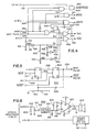
- FIG. 3 contains the logic that decodes the signals presented by the peripheral connector 106 and generates the control signals that establish communication between the computer 102 and the speech processor 200.
- the signals shown in the lower half of the figure do not require decoding. Only the PHASE O timing signal 228 is passed through a buffering gate 310 so that the peripheral connector is not unduly loaded.
- Peripheral connector 106 address leads A7 through A15 are decoded by gates 304, 306, and 308 such that a signal C08X 312 appears whenever the binary address "1100 0000 lxxx xxxx" (where x may be "0" or "1") is applied to the peripheral connector address leads.
- the signal C08X 312 passes through a gate 404 and becomes the REFRESH signal 262 that causes the 2-1 select 210 to disconnect the refresh 8-bit counter 264 from the speech memory 214 and connect it instead to the counters 218 and 220 whenever the computer 102 may be attempting to feed data into the speech memory 214.
- the peripheral connector DEVICE SELECT signal which selects a peripheral port whenever the computer 102 addresses locations between $CONO and $CONF (where N is the peripheral connector port number), enables a 3 to 8 line decoder 302 to decode address lines AO, Al, A2, and A3 into the four control signals WOM 282 (generated by address $CONO), COUNT O 217 (generated by address $CON1), SETNMI 219 (generated by address $CONZ), and ENABLE 242 (generated by address $CON3).
- the SETNMI signal 219 sets a flip-flop comprising cross connected NAND gates 301, 303. When the flip-flop is set, it generates the NMI signal 221 to the microcomputer 202. The flip-flop is reset when the computer 102 causes the generation of the count O signal 217.
- the speech system 200 timing signals that govern the operation of the speech memory 214 are generated by the timing logic 400.
- the PHASE O timing signal 228 from the computer 102 is fed through a series of three inverting time delay networks 406, 408, and 410.
- the first inverting time delay network 406 feeds the PHASE O signal 228 through 1,000 ohm resistor 412 and a 180 picofarad capacitor 414 to ground.
- the delayed PHASE O pulse at the node 416, where elements 412 and 414 join, is inverted and squared up by passage through a gate 418 to become a PHASE 1 signal 420, as shown in FIG. 9.
- the PHASE 1 signal 420 is fed through inverting time delay networks 408 and 410 to become the PHASE 2 signal 422 and the PHASE 3 signal 424 whose timing relationships to the PHASE 1 signal 420 are shown in FIG. 9.
- the network 408 includes a 1,000 ohm resistor 426 and a 150 picofarad capacitor 428, while the network 410 includes a 1,000 ohm resistor 430 and a 100 picofarad capacitor 432.
- the PHASE O signal 228 controls the 2-1 select 212 that alternately couples the counters 218 and 220 to the speech memory 214 address input.
- an RAS signal 236 pulse loads one of the two counter's address signals into the memory 214.
- a CAS signal 234 pulse loads the other counter's address signals into the memory 214. The CAS signal 234 then advances the counter 220 so that the next sequential location in the memory 214 is addressed during the next PHASE O timing cycle.
- the RAS signal 236 is formed by passing both the PHASE 0 and PHASE 1 signals through a gate 434 at whose output a signal appears whenever either of these two signals is present.
- the absence of an output from the gate 434 is defined to be the presence of the inverted RAS signal 236 which goes high momentarily whenever the PHASE O signal goes low and then drops when the PHASE 1 signal goes high.
- the gate 436 prevents the CAS signal 234 from arising except when the PHASE O and PHASE 2 signals are both high. Accordingly, the CAS signal can only arise towards the middle of the period when the PHASE O signal is high, and the CAS signal terminates (and advances the counter 220 in FIG. 2) in synchronism with the termination of the PHASE O signal 228.
- the CAS signal arises from either the WOM signal 282 or the NEXT PULSE signal 254 flowing through the combining gate 438 and the blocking gate 436, and these respectively arise when the computer 102 (which generates the WOM signal) or the microcomputer 202 (which generates the NEXT PULSE signal) attempt to access the speech memory 214.
- the signal R/W 284 from the peripheral connector which distinguishes a data read request from a data write request, is passed through a blocking gate 402 to become the WRITE signal 232 that enables the speech memory 214 to accept new data.
- the timing of the WRITE signal 232 is adjusted so that it is, in effect, a CAS signal whose onset is delayed slightly to coincide with the time when the computer 102 presents data to the data bus DO-D7 230.
- the CAS signal 234 is passed through a gate 440 that is disabled at the onset of the CAS signal by the delayed onset of the PHASE 3 signal 424.
- the delayed-onset CAS signal 442 that flows from the gate 440 is fed into the gate 402 to determine the timing of the WRITE signal.
- the gate 402 blocks the signal R/W from becoming the WRITE signal 232 whenever the NEXT PULSE signal 254 signals that the microprocessor 202 is reading data out of the memory.
- the gate 402 also blocks the signal R/W whenever the WOM signal 282 is absent, since memory WRITE cycles are signaled by the WOM signal 282.
- the NEXT signal 252 generated by the microprocessor must be converted into a carefully timed NEXT PULSE 254 (FIGS. 2, 5 and 9), and this conversion is carried out by the pulse generator 500.
- the NEXT signal 252 leading edge sets a JK master-slave flip flop 502 whose Q output 506 enables the J input of a second JK master-slave flip flop 504.
- the next trailing edge of a PHASE O signal 228 toggles the flip flop 504, and it initiates the NEXT PULSE signal at 254.
- the NEXT trailing edge of a PHASE O signal 228 clears the flip flop 504 and terminates the NEXT PULSE signal 254.
- a 510 picofarad capacitor 508 feeds the trailing edge of the NEXT PULSE signal 254 back to the inverted clear terminal of the flip-flop 502 which is connected to ground and + 5 volts by a pair of 1,000 ohm resistors 510 and 512. The circuit thereby resets itself and awaits the next NEXT signal 252.
- the audio system 600 is a conventional audio amplifier that accepts the AUDIO signal 602, adjusts its level, filters it, amplifies it, and applies it to a loudspeaker 604.
- the AUDIO signal 602 is first applied across 1,000 ohm resistor 606 and a 10,000 ohm potentiometer 608 connected in parallel to ground.
- a 0.1 microfarad capacitor 610 connects the slider 612 of the potentiometer 608 to a 4-pole active filter 614 having a 4,000 Hz low-pass cutoff characteristic.
- the filter 614 connects to the input lead 6 of an integrated circuit audio amplifier 622.
- a feed back network comprising a 100,000 ohm resistor 620 connected in parallel with a 510 picofarad capacitor 630 connect pins 2 and 6 of the amplifier 622 together.
- Pin 1 is connected to ground by a 5 microfarad capacitor 632, an a 100 microfarad capacitor connects the amplifier 622 output pin 8 to the speaker 604 which has its other lead connected to ground.
- the amplifier 622 is a National Semiconductor No LM380 audio amplifier.
- FIG. 7 connected by a fuse 702 and an "off-on" switch 704 to a 120 volt source of A.C. power.
- the power supply 700 is conventional.
- the +12 volt power supply 700 can power a regulated +5 volt power supply 800 shown in FIG. 8, which can feed at +5 volt power back to the speech processor 200 (FIG. 2) to reduce or eliminate the drain on the power supply of the computer 102.
- the regulated +5 volt power suppply is conventional.
- FIGURE 2 the microcomputer 202 is shown containing a processor control program 204 which controls its operations.
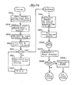
- FIGS. 22 to 29 constitute a complete flow diagram of the program logic of the control program 204. These flow diagrams are explained below.
- program execution commences at SCAN and thereafter periodically returns to SCAN when all other tasks are finished.
- the microcomputer begins at 2204 by generating a momentary LOAD signal 248 to reset the bistable 240 and load or clear the speech memory address counters 218 and 220.
- the microcomputer then clears the "busy" bit of its status work at Port B and enters into a loop at 2208 and 2210 where it repeatedly tests for the presence of a BDEN signal 241, indicating the computer 102 has set the bistable 240 and wishes some task performed.
- the microcomputer sets the Port B "busy" bit, and at 2214 it fetches the two byte command from addresses O and 1 of the speech memory 214. If the command is a number less than or equal to $25F, it is a segment address--a simple request to have a particular speech segment reproduced. Detecting this at 2216, the microcomputer stores zero in location PHRASE to indicate the segment address is stored in speech memory location $0000, and it stores a 1 in location PHRASES, since this is the number of phrases to be reproduced. Program control then continues at SPEECH in FIG. 20.
- the microcomputer checks at 2220 for a request to process a multiple set of commands.
- the most significant byte of such a command is $80, and the least significant byte is the number of commands (presumably stored sequentially in speech memory locations $0002, $0004, etc.) that are to be executed, up to a maximum of $3F commands. If this is a multiple command processing request, the microcomputer stores the six least significant bits of the command (representing the number of commands to be executed) in location PHRASES and stores a 1 in the location PHRASE to indicate the first phrase or command to be executed is in the second 16-bit location of the speech memory (e.g., locations $002 and $0003). Then program control continues at SPEECH in FIG. 23.
- the microcomputer checks at 2224 to see if the two most significant bits are set, indicating this is a time delay or pause request, with the remaining bits indicating the length of the pause measured in 12.5 millisecond intervals. If so, the subroutine DODELAY in FIG. 26 is called at 2226. If not, then an error action is taken at 2228. In either case, program control returns to SCAN where the bistable 240 is cleared and the "busy" bit is also cleared and the microprocessor idles once more, awaiting the next ENABLE command 242 from the computer 102.
- the routine SPEECH begins at 2302 by checking to see if a multiple command sequence is being processed. If so, then program control shifts to 2318.
- the memory address counter is cleared to zero by accessing the first two bytes of data in the speech memory. Then the desired phrase number (the number of the 16-bit location where the next command to be executed is stored) is placed in index register X at 2320.
- a loop is then entered during each pass of which the next two speech memory bytes are read and index register X is decremented, with the loop (steps 2322, 2323, and 2324) terminating at 2324 when X equals O and the next command to be executed has been retrieved. "1" is then added to the number in PHRASE so that the next command in the speech memory will be selected the next time.
- the command just retrieved is tested to see if it is a segment address (less than $C000). If it is, program control continues at SINGLE where single segment address commands are also processed. If a time delay request, the subroutine DODELAY is called at 2329 to process the request. One is subtracted from the remaining-to-be-executed command count in location PHRASES (at 2330), and PHRASES is checked to see if it equals zero. If not, program control branches back to SPEECH, and the next command is executed. If no more commands remain the "busy" bit is cleared at 2334, and program control returns to SCAN in FIG. 22 where the microcomputer 202 idles once again.
- step 2304 the segment address is shifted and thereby multiplied by two to convert it into a relative byte address. Then $0080, the base address of the speech data vectors storage area (3004 in FIG. 30), is added to the relative address to produce the two byte absolute address of the two locations containing the starting address of the segment of speech data.
- step 2306 the most significant address byte is presented to microcomputer Port A for presentation to address counter 218, and at 2308 a LOAD signal is generated to load this byte into counter 218 and to zero counter 220.
- the least significant address byte is placed in index register X, and a loop (2312, 2314, 2316) is entered into during which NEXT signal pulses are generated to increment the counter 220, while the index register X is decremented, until register X contains zero and counter 220 now contains a count value equal to the least significant address byte.
- Step 2402 Program control continues at TABLED in FIG. 24 where the vector address is retrieved by the generation of two NEXT pulses (step 2402). Now the two bytes are the most and least significant bytes of the actual starting address of the locations containing the speech data. Steps 2404, 2406, 2408, 2410, 2412, and 2414 are now executed in a manner virtually identical to steps 2306 to 2316 just described in the last paragraph, leaving the counters 218 and 220 containing the actual starting address of the speech data when program control continues at DATRADDR.
- the microprocessor begins transferring the speech data to the voice synthesizer 216.
- the value $FF is presented to the synthesizer over Port D.
- a 300 microsecond delay is generated at 2418.
- the subroutine SAY (FIG. 27) is called upon to transfer the speech data to the synthesizer.
- 1 is subtracted from the number of phrases or commands waiting to be processed. If more remain (2424), then program control returns to SPEECH in FIG. 23, and the next command is processed. If none remain, step 2426 clears the BUSY bit, and program control returns to SCAN in FIG. 22 where the microcomputer idles once again.
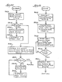
- the subroutine DODELAY in FIG. 25 causes the speech processor to idle for the number of 12.5 millisecond time intervals indicated by the 14 least significant bytes of the delay command.
- the eight least significant bytes are entered into the microprocessor's accumulator, and then a loop (2504, 2506, 2508) is entered. Within this loop, the accumulator is decremented every 12.5 milliseconds until it equals zero.
- the least significant bits of the most significant byte are stored in location ADDRO.
- a loop is then entered (2512, 2514, 2516). Within this loop, the number in location ADDRO is decremented every 3.2 seconds until it becomes zero.
- FIG. 27 presents the subroutine SAY that transfers data from the speech memory 214 to the voice synthesizer 216 until an entire phrase has been transferred.
- a loop (2702, 2704, 2706) is entered into during which the synthesizer status bits are retrieved and the talk status bit is checked over and over until it is cleared.
- $06 is presented to the synthesizer over Port D of the microprocessor.
- a byte of data is tranferred from the speech memory 214 to the voice synthesizer 216 (steps 2712 and 2724).
- Program control then continues at REFILL.
- the value "8" is placed into the index register X to serve as a loop counter. Then a loop is entered into (2718, 2720, 2722, 2724). During eight passes through this loop, eight bytes of data are transferred between the speech memory 214 and the voice synthesizer 216. Index register X is decremented during each pass, and when X contains zero, program control loops at 2726 and 2728 until the INT signal line from the speech processor goes high. Then at 2730 the synthesizer status bits are retrieved and checked. If they equal "6", then program control returns to REFILL, and another 8 bytes of data are transferred. If they equal "4", the loop at 2726 and 2728 is commenced until the next interrupt. If they equal zero, then the speech segment data transfer is done. Any other result causes an error return from the subroutine. The value tests are carried out at 2732, 2734, and 2736.
- the subroutine WRITE in FIG. 26 is called upon by the subroutine SAY in FIG. 27 to transfer a byte of data from the microprocessor to the speech synthesizer. Since the data to be transferred is passed to the subroutine in the accumulator, its contents are presented to Port D, the data lines leading to the synthesizer (step 2602).
- the number $FB is applied to Port C to send a W signal to the synthesizer, signalling the data is ready (step 2604).
- a loop is then entered at 2606-2608 that samples the synthesizer RDY signal until it drops.
- $FF is applied to Port C to terminate the WS signal (2610).
- the STATUS subroutine in FIG. 28 returns in the accumulator three status bits obtained from the synthesizer.
- the number $FF is presented at Port D to the synthesizer data lines.
- the value $EF is presented at Port C to generate the synthesizer RS (read select) input signal.
- the system loops while continuously checking the "RDY" signal bit which is the most significant Port C bit. When it goes low, synthesizer status data is read from Port D into index register X (2810). $FF is presented to Port C to terminate the RS signal (2812). The status data is transferred to the accumulator (2814), right shifted until bits 5, 6 and 7 are bits 0, 1, and 2 (2816), and masked 2818.
- This frequently-called-upon subroutine reads a byte of data from the speech memory 214 and increments the counters 218 and 220. It begins at 2902 by generating the NEXT signal 252 by presenting the number $DF to Port C. At 2904, it terminates the NEXT signal 252 and simultaneously generates an EN DATA signal 260 by presenting the number $F7 to Port C. Next at 2906, the microprocessor reads in the byte of memory data presented to Port A by the enabled latch 256. Finally at 2908, all signals are terminated by presenting $FF to Port C.
- the speech control program 104 is a program within the computer 102 that calls upon the speech processor 200 to generate individual and sets of speech segments and time delays.
- the present invention contemplates the development of many different types of speech control programs, including, for example, computer-aided-instructional programs that do many things in addition to and, perhaps, simultaneously with the generation of speech. All such programs will include program elements that can pass data and commands over the peripheral connector 106 to the speech processor 200 and test the status of the processor 200, particularly whether it is busy. So the speech control program described below is simply one example of how the speech processor 200 can be used in conjunction with the computer 102. The example chosen is a test program used by the developers of this system to emulate the operation of the speech processor 200 by computer-aided-instructional (CAI) programs.
- CAI computer-aided-instructional
- the emulation program described below permits a human to type out the number of the command or commands that are to be executed.
- This emulation program contains all of the "hooks" that any program would need to function as the speech control program element of the present invention, so it serves to illustrate the present invention quite nicely. It is also a relatively simple program.
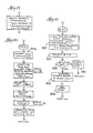
- FIGS. 10 and 11 together illustrate the main flow of the speech control program 104.
- the program at 1006 asks if you wish to have the "soundtrack" or sound data set loaded. If you do, the program at 1010 transfers the sound data set from disk storage into the computer 102 memory and from there into the memory 214, assumedly filling locations $0080 to the end of the memory 3002 or some point short of the end of the memory (see FIG. 30). A frequently used multiple command sequence might be loaded into area 3008 at the same time.
- the program at 1012 and 1014 now asks you what you wish to do next. Your answer is analyzed at 1102-1108 in FIG. 11. If you type A, indicating you wish to issue a single command, at 1102, you are routed to the SIMA routine in FIG. 12. If you typed B and thereby select a multiple command set, at 1104, you are routed to SIMB in FIG. 13. If you type C, the speech processor is reset at 1110, and program control returns to the very beginning with the reinitialization of everything at INIT in FIG. 10. If you type X, the program at 1108 returns you to the Apple monitor at 1112. Any other response simply returns program control to SIMENU in FIG. 10 where the same question is repeated.
- FIG. 12 presents the SIMA program that lets you simulate the passing of single commands to the speech processor 200.
- the status of the speech processor 200 is checked. If the "busy" bit is set, program control returns to the prompting point SIMULAT in FIG. 10. Otherwise, the speech processor is reset at 1204. Two hexadecimal digits are-solicited at 1206 and checked for illegality at 1208. If illegal, they are rejected, and two more digits are requested. Then at 1210 the speech processor is placed into service. Program control then returns to the prompting point SIMULAT in FIG. 10.
- the SIMB routine permits you to supply multiple commands to the speech processor 200. It begins at 1302 by checking to see if the speech processor is in use.
- the number of commands is stored in location $0001 of the speech memory 214.
- a loop encompassing steps 1318, 1320, 1322, and 1324 is entered.
- two phrase or time delay hexadecimal digits are solicited, accepted, checked for errors, and stored in sequentially adjacent locations in the speech memory 214 beginning with location $0002. This process continues until an error transfers program control back to SIMB or until the proper number of phrases and time delays have been provided.
- the speech processor is placed in operation at 1326, and program control returns to the SIMULAT reprompting entry point in FIG. 10.
- FIGS. 14-16 and 19 disclose some of the more detailed aspects of the interaction between programs in the computer 102 and the speech processor 200.
- FIG. 14 describes a routine 1002 that searches for a peripheral connector 106 slot address from which the speech processor 200's identifying code $5B can be retrieved.
- This routine 1002 is part of the initialization routine INIT at the top of FIG. 10.
- FIG. 15 describes a routine used to inquire of the speech processor's status bits as to how large a memory the speech processor has. After initializing the processor at 1502, setting its counters to zero count, this routine stores the special command $FFOO in the processor (Note: the speech processor routine that responds to this special command is not disclosed in this application which assumes a fixed sized memory). Note that the bytes $FF and $00 are simply stored in computer 102's memory location "$C080 + $10 (Slot)" which means in location $C090 if the processor is in slot 1, and so on. The speech processor is then enabled at 1506, and a 255 millisecond timer is established at 1508. A loop. (1510, 1512, 1516) is then entered.
- this loop uses the machine language addressing scheme indicated at 1510 to transfer status data from the microcomputer 202, through the latch 246, and into the accumulator of computer 102.
- bit 4 the "busy" bit
- Bits 1 and 2 indicate memory size at 1514. If the speech processor remains busy for too long, step 1516 routes program control to an error routine 1518.
- FIG. 16 illustates the, details of transferring speech data from a disk file into the speech memory 214.
- the file "soundtrack" is first transferred from a disk file into core memory at 1602. Then, one byte at a time, the data is presented to the memory location whose address is computed as shown at 1604.
- FIG. 17 illustrates how the speech processor can be reset.
- the slot number (of the peripheral connector slot where the speech processor 200 resides) is placed in index registry Y and is thereby added to the base address $C081 to produce the proper address.
- the "1" least significant digit energizes the B input of the 3 to 8 line decoder 302 (FIG. 3) and causes the COUNT O signal 217 to reset the counters 218 and 220 (FIG. 2) to zero.
- FIG. 19 is similar to FIG. 17 but illustrates how the speech processor is placed into operation by addressing the base address $C083 instead of $C081.
- the "3" actuates inputs A and B and therefore actuates output 3 of the 3 to 8 line decoder 302 (FIG. 3) which is the ENABLE signal 1242 that sets the bistable 240 and places the speech processor 200 into operation.
- the subroutine SAYTHIS (FIG. 18) is used by both the routines SIMA (FIG. 12) and SIMB (FIG. 13) to solicit hexadecimal digits, check them for errors, pack pairs of them into bytes, and feed the bytes to the speech processor 200.
- the PACK subroutine accepts the digits, checks them for errors, and forms a byte from them. Steps 1806 and 1808 check to insure the digits are valid speech or delay commands. Then at 1810 the first byte of the command is fed into the speech memory 214. Then PACK solicits two more hexadecimal digits at 1812, and these are transferred to the memory 214.
- the PACK subroutine (FIG. 20) simply accepts two ASCII keystrokes, converts them to hexadecimal, error checks them, and packs them into a byte.
- the BUSY subroutine determines the busy status of the speech processor 200 by loading the accumulator from the address indicated at 2110 and selecting the fourth bit to test 2112 and 2114. The carry flag is used as a return argument at 2116 and 2120. If the processor 200 is busy, the message at 2118 is displayed.
- the first set of programs are designed for installation in an Apple II+ microcomputer and for use in conjunction with that computer.
- a complete technical description of the Apple II+ computer, as well as a description of the mnemonic instruction language used below, can be found in the book entitled "Apple II Reference Manual” published in 1979 by Apple Computer, Incorporated. Pages 118 to 128 of that book introduce the 6502 microprocessor instruction set which is used in the programs that follow. Further information can be found in the book “Programming the 6502” writen by Rodney Zaks and published by Sybex Incorporated, Berke- ley, California.
- the Apple II+ peripheral connector bus and all of its signals, including those shown in FIG. 3, is described on pages 106 to 109 of the "Apple II Reference Manual," and the timing of these signals is indicated on page 91 of that book.
- the second set of programs are designed for installation in the read-only-memory portion of an R6500/1 microcomputer system that forms a portion of the speech processor.
- This system is described in document No. 29650 N48 published in June of 1979 by Rockwell International Corporation, a manufacturer of this system (the document is entitled: "R6500 Microcomputer System Product Description: R6500/1 One-Chip Microcomputer.")
- the mnemonic instruction language for the R6500/1 is identical to that for the 6502 processor used in the Apple II+, so no separate reference book on the R6500/1 is required to understand the second set of programs.
- the R6500/1 contains 64 bytes of RAM positioned at memory addresses $0 to $03F and 2K of ROM positioned at $800 to $FFF. All variables are stored in RAM and all programs are stored in ROM. Its four external ports A, B, C and D are located at addresses $80, $81, $82 and $83, respectively.
- FIGS. 10 through 21 of the drawings constitute a complete, detailed flow diagram of the programs that follow.
- Program address and subroutine names are the same in both the flow diagram and in the programs that follow.
- the main program is set out first, and it is followed by the subroutines which are arranged in alphabetical order.
- Certain locations within the address space of the computer enable one to access the peripheral connector bus and to communicate over the bus with the speech processor. Those locations are assigned symbolic addresses which are indicated on the first page of the program listing that follows.
- the location SLOT contains the slot number where the speech processor is located within the computer, and this slot number is frequently used in computing the addresses which are assigned to the various symbolic names.
- the "SUBROUTINE LINKAGES" listed above are linkages to external subroutine utilities which form a part of the operating system of the computer and which facilitate single byte communication between the programs and the user sitting before the keyboard and display.
- the following program initializes the computer, searching the accessory slots for the speech processor.
- the routine FILL transfers speech data from the disk file SOUNDTRACK into the speech processor's RAM and illustrates how speech data is loaded into the speech processor.
- the routine SIMA accepts a single speech phrase number and passes it to the speech processor.
- the routine SIMB accepts a multiple speech phrase request and passes it on to the speech processor.
- FIGS. 22 through 29 of the drawings constitute a complete, detailed flow diagram of the programs that follow.
- Program address and subroutine names and some variable names are the same in both the flow diagram and in the programs that follow.
- the main program is set out first, and it is followed by the subroutines which are arranged in alphabetical order.
- microcomputer port A is addressed as "PRE64”
- port B is addressed as “STAT65”
- port C is addressed as “MASTER”
- port D is addressed as “D5220.”
- the bit assignments within these locations to external signals is also set out in this section.
- the NEXT signal is called NXT and is asigned to bit 5
- the EN DATA signal is called EN and is assigned to bit 3
- the LOAD signal ' is called LD and is assigned to bit 1
- the BD EN signal is called BDEN and is assigned to bit O.
- the four remaining signals, RDY, INT, RS, and WS all flow between the voice synthesizer and the microcomputer.
- the following table assigns names and locations to variables and assigns names to the system ports and control register.
- the program segment which follows initializes the microcomputer. Some portions which have been omitted determine how much memory is present and set a value in location NUMBITS to indicate the memory size. For purposes of this description, a full 64K memory is assumed, and NUMBITS therefore contains the integer 3 to signal this fact. The program comments are retained unchanged from the actual program listing.
- the main processor control program listing follows. It is flow charted in FIGS. 22 through 25, starting with the entry SCAN in FIG. 25.
- the SPEECH segment is flow charted beginning in FIG. 23 and the TABLED segment is flow charted in FIG. 24.
- the subroutines that form a portion of the processor control programs are set forth below, together with the comments from the actual program listing.
- the subroutines are set forth in alphabetical order. Flow charts of the more important subroutines appear in FIGS. 25 to 29 of the drawings.
Landscapes
- Engineering & Computer Science (AREA)
- Theoretical Computer Science (AREA)
- Health & Medical Sciences (AREA)
- Audiology, Speech & Language Pathology (AREA)
- General Health & Medical Sciences (AREA)
- Human Computer Interaction (AREA)
- Physics & Mathematics (AREA)
- General Engineering & Computer Science (AREA)
- General Physics & Mathematics (AREA)
- Electrophonic Musical Instruments (AREA)
- Machine Translation (AREA)
Applications Claiming Priority (4)
| Application Number | Priority Date | Filing Date | Title |
|---|---|---|---|
| US469482 | 1983-02-24 | ||
| US06/469,482 US4639877A (en) | 1983-02-24 | 1983-02-24 | Phrase-programmable digital speech system |
| US06/534,490 US4675840A (en) | 1983-02-24 | 1983-09-21 | Speech processor system with auxiliary memory access |
| US534490 | 1983-09-21 |
Publications (1)
| Publication Number | Publication Date |
|---|---|
| EP0121293A1 true EP0121293A1 (fr) | 1984-10-10 |
Family
ID=27042773
Family Applications (1)
| Application Number | Title | Priority Date | Filing Date |
|---|---|---|---|
| EP84300315A Withdrawn EP0121293A1 (fr) | 1983-02-24 | 1984-01-19 | Système de parole numérique à phrase programmable |
Country Status (4)
| Country | Link |
|---|---|
| US (1) | US4675840A (fr) |
| EP (1) | EP0121293A1 (fr) |
| AU (1) | AU565269B2 (fr) |
| CA (1) | CA1207455A (fr) |
Cited By (3)
| Publication number | Priority date | Publication date | Assignee | Title |
|---|---|---|---|---|
| FR2576701A1 (fr) * | 1985-01-29 | 1986-08-01 | Retaureau Francois | Dispositif d'extension permettant la synthese de la parole, de la musique et des bruits |
| GB2248371A (en) * | 1990-09-27 | 1992-04-01 | Fung Sidney Kwok On | Electronic voice databank |
| GB2277854A (en) * | 1993-05-04 | 1994-11-09 | Martin David Risely | Replaying speech from the parallel port of a personal computer |
Families Citing this family (11)
| Publication number | Priority date | Publication date | Assignee | Title |
|---|---|---|---|---|
| JPS6199198A (ja) * | 1984-09-28 | 1986-05-17 | 株式会社東芝 | 音声分析合成装置 |
| JPS6199199A (ja) * | 1984-09-28 | 1986-05-17 | 株式会社東芝 | 音声分析合成装置 |
| US4799144A (en) * | 1984-10-12 | 1989-01-17 | Alcatel Usa, Corp. | Multi-function communication board for expanding the versatility of a computer |
| US5029214A (en) * | 1986-08-11 | 1991-07-02 | Hollander James F | Electronic speech control apparatus and methods |
| US4949382A (en) * | 1988-10-05 | 1990-08-14 | Griggs Talkwriter Corporation | Speech-controlled phonetic typewriter or display device having circuitry for analyzing fast and slow speech |
| US5201055A (en) * | 1989-11-03 | 1993-04-06 | Compaq Computer Corporation | Multiprocessing system includes interprocessor encoding and decoding logic used for communication between two cards through reduced addressing lines |
| DE4334313A1 (de) * | 1993-10-08 | 1995-04-13 | Sel Alcatel Ag | Verfahren zum Verwalten eines Sprachspeichers und Vorrichtung dafür |
| JP3252877B2 (ja) * | 1994-02-08 | 2002-02-04 | 富士通株式会社 | 記憶データ確認方法及び装置 |
| JPH09244893A (ja) * | 1996-03-11 | 1997-09-19 | Hitachi Ltd | 並列計算機システムにおける一括転送方法 |
| US5850628A (en) * | 1997-01-30 | 1998-12-15 | Hasbro, Inc. | Speech and sound synthesizers with connected memories and outputs |
| US20020052744A1 (en) * | 2000-10-31 | 2002-05-02 | Chaur-Wen Jih | Synchronized output speech synthesizer device |
Citations (2)
| Publication number | Priority date | Publication date | Assignee | Title |
|---|---|---|---|---|
| US4335277A (en) * | 1979-05-07 | 1982-06-15 | Texas Instruments Incorporated | Control interface system for use with a memory device executing variable length instructions |
| EP0054620A2 (fr) * | 1980-12-19 | 1982-06-30 | International Business Machines Corporation | Terminal de traitement de données |
Family Cites Families (43)
| Publication number | Priority date | Publication date | Assignee | Title |
|---|---|---|---|---|
| US30991A (en) * | 1860-12-18 | Shutter-operator | ||
| US3654619A (en) * | 1968-12-20 | 1972-04-04 | Dynamic Typing Inc | Audio-visual instructional system with synchronized visual and audio presentations |
| US3641496A (en) * | 1969-06-23 | 1972-02-08 | Phonplex Corp | Electronic voice annunciating system having binary data converted into audio representations |
| US4060848A (en) * | 1970-12-28 | 1977-11-29 | Gilbert Peter Hyatt | Electronic calculator system having audio messages for operator interaction |
| GB1460148A (en) * | 1973-04-26 | 1976-12-31 | Lucas Industries Ltd | Data transmission system |
| US4000565A (en) * | 1975-05-05 | 1977-01-04 | International Business Machines Corporation | Digital audio output device |
| US4060915A (en) * | 1976-08-02 | 1977-12-06 | Conway Malcolm J | Mental image enhancement apparatus utilizing computer systems |
| US4301328A (en) * | 1976-08-16 | 1981-11-17 | Federal Screw Works | Voice synthesizer |
| US4185169A (en) * | 1977-02-04 | 1980-01-22 | Sharp Kabushiki Kaisha | Synthetic-speech calculators |
| US4211892A (en) * | 1977-02-15 | 1980-07-08 | Sharp Kabushiki Kaisha | Synthetic-speech calculators |
| US4185170A (en) * | 1977-04-30 | 1980-01-22 | Sharp Kabushiki Kaisha | Programmable synthetic-speech calculators or micro computers |
| US4099236A (en) * | 1977-05-20 | 1978-07-04 | Intel Corporation | Slave microprocessor for operation with a master microprocessor and a direct memory access controller |
| US4331836A (en) * | 1977-06-17 | 1982-05-25 | Texas Instruments Incorporated | Speech synthesis integrated circuit device |
| BE856402A (fr) * | 1977-07-01 | 1978-01-02 | Centre Rech Metallurgique | Procede pour ameliorer la proprete de surface de la tole d'acier |
| US4176470A (en) * | 1977-09-01 | 1979-12-04 | Emerson O. Fosner | Educational reinforcement apparatus |
| USRE30991E (en) | 1977-09-26 | 1982-07-06 | Federal Screw Works | Voice synthesizer |
| US4215240A (en) * | 1977-11-11 | 1980-07-29 | Federal Screw Works | Portable voice system for the verbally handicapped |
| US4163120A (en) * | 1978-04-06 | 1979-07-31 | Bell Telephone Laboratories, Incorporated | Voice synthesizer |
| US4335275A (en) * | 1978-04-28 | 1982-06-15 | Texas Instruments Incorporated | Synchronous method and apparatus for speech synthesis circuit |
| US4304964A (en) * | 1978-04-28 | 1981-12-08 | Texas Instruments Incorporated | Variable frame length data converter for a speech synthesis circuit |
| US4189779A (en) * | 1978-04-28 | 1980-02-19 | Texas Instruments Incorporated | Parameter interpolator for speech synthesis circuit |
| US4209781A (en) * | 1978-05-19 | 1980-06-24 | Texas Instruments Incorporated | MOS Digital-to-analog converter employing scaled field effect devices |
| US4312065A (en) * | 1978-06-02 | 1982-01-19 | Texas Instruments Incorporated | Transparent intelligent network for data and voice |
| US4317197A (en) * | 1978-06-02 | 1982-02-23 | Texas Instruments Incorporated | Transparent intelligent network for data and voice |
| US4316283A (en) * | 1978-06-02 | 1982-02-16 | Texas Instruments Incorporated | Transparent intelligent network for data and voice |
| US4317196A (en) * | 1978-06-02 | 1982-02-23 | Texas Instruments Incorporated | Transparent intelligent network for data and voice |
| US4375097A (en) * | 1978-06-02 | 1983-02-22 | Texas Instruments Incorporated | Transparent intelligent network for data and voice |
| US4334306A (en) * | 1978-06-02 | 1982-06-08 | Texas Instruments Incorporated | Transparent intelligent network for data and voice |
| US4234761A (en) * | 1978-06-19 | 1980-11-18 | Texas Instruments Incorporated | Method of communicating digital speech data and a memory for storing such data |
| JPS5574600A (en) * | 1978-11-30 | 1980-06-05 | Sharp Kk | Speech annunciation control system |
| US4272649A (en) * | 1979-04-09 | 1981-06-09 | Williams Electronics, Inc. | Processor controlled sound synthesizer |
| US4304965A (en) * | 1979-05-29 | 1981-12-08 | Texas Instruments Incorporated | Data converter for a speech synthesizer |
| JPS5664100U (fr) * | 1979-10-24 | 1981-05-29 | ||
| US4281994A (en) * | 1979-12-26 | 1981-08-04 | The Singer Company | Aircraft simulator digital audio system |
| US4296279A (en) * | 1980-01-31 | 1981-10-20 | Speech Technology Corporation | Speech synthesizer |
| US4319083A (en) * | 1980-02-04 | 1982-03-09 | Texas Instruments Incorporated | Integrated speech synthesis circuit with internal and external excitation capabilities |
| US4323732A (en) * | 1980-02-04 | 1982-04-06 | Texas Instruments Incorporated | Speech synthesis system with alternative coded or uncoded parameter formats |
| JPS56123002A (en) * | 1980-03-03 | 1981-09-26 | Sharp Corp | Electronic apparatus |
| US4337375A (en) * | 1980-06-12 | 1982-06-29 | Texas Instruments Incorporated | Manually controllable data reading apparatus for speech synthesizers |
| US4403965A (en) * | 1980-10-01 | 1983-09-13 | Texas Instruments Incorporated | Electronic teaching apparatus |
| US4398059A (en) * | 1981-03-05 | 1983-08-09 | Texas Instruments Incorporated | Speech producing system |
| US4415767A (en) * | 1981-10-19 | 1983-11-15 | Votan | Method and apparatus for speech recognition and reproduction |
| US4519027A (en) * | 1982-06-10 | 1985-05-21 | Cybersonic Corporation | Industrial control, communications and information system |
-
1983
- 1983-09-21 US US06/534,490 patent/US4675840A/en not_active Expired - Fee Related
-
1984
- 1984-01-19 EP EP84300315A patent/EP0121293A1/fr not_active Withdrawn
- 1984-01-19 AU AU23619/84A patent/AU565269B2/en not_active Ceased
- 1984-02-01 CA CA000446578A patent/CA1207455A/fr not_active Expired
Patent Citations (2)
| Publication number | Priority date | Publication date | Assignee | Title |
|---|---|---|---|---|
| US4335277A (en) * | 1979-05-07 | 1982-06-15 | Texas Instruments Incorporated | Control interface system for use with a memory device executing variable length instructions |
| EP0054620A2 (fr) * | 1980-12-19 | 1982-06-30 | International Business Machines Corporation | Terminal de traitement de données |
Non-Patent Citations (5)
| Title |
|---|
| ELECTRONIC DESIGN, vol. 29, 11th June 1981, pages 213-218, Waseca, US D.O. WICKEY: "Synthesizer chip translates LPC to speech economically" * |
| ELECTRONICS, vol. 51, no. 3, 2nd February 1978, pages 6E,8E,10E, New York, US "Flexible voice response unit will have many messages for telephone subscribers" * |
| ELEKTRONIK, no. 11, 1980, pages 67-72, Munich, DE H. SCHMID: "Schnittstellen zwischen monolithischen Prozessoren und der Aussenwelt" * |
| INTERNATIONAL ELECTRONICS, vol. 53, no. 3, 10th February 1981, pages 122-125, New York, US KUN-SHAN LIN et al.: "Software rules give personal computer real word power" * |
| MINI-MICRO SYSTEMS, vol. 15, no. 12, December 1982, pages 146-160, Denver, Colorado, US T.B. SCHALK et al.: "Voice synthesis and recognition" * |
Cited By (3)
| Publication number | Priority date | Publication date | Assignee | Title |
|---|---|---|---|---|
| FR2576701A1 (fr) * | 1985-01-29 | 1986-08-01 | Retaureau Francois | Dispositif d'extension permettant la synthese de la parole, de la musique et des bruits |
| GB2248371A (en) * | 1990-09-27 | 1992-04-01 | Fung Sidney Kwok On | Electronic voice databank |
| GB2277854A (en) * | 1993-05-04 | 1994-11-09 | Martin David Risely | Replaying speech from the parallel port of a personal computer |
Also Published As
| Publication number | Publication date |
|---|---|
| US4675840A (en) | 1987-06-23 |
| AU565269B2 (en) | 1987-09-10 |
| AU2361984A (en) | 1984-08-30 |
| CA1207455A (fr) | 1986-07-08 |
Similar Documents
| Publication | Publication Date | Title |
|---|---|---|
| EP0121293A1 (fr) | Système de parole numérique à phrase programmable | |
| US4516260A (en) | Electronic learning aid or game having synthesized speech | |
| US4639877A (en) | Phrase-programmable digital speech system | |
| EP0048835A2 (fr) | Appareil d'enseignement électronique | |
| US4234761A (en) | Method of communicating digital speech data and a memory for storing such data | |
| US4946391A (en) | Electronic arithmetic learning aid with synthetic speech | |
| Smith | Examination by computer | |
| KR930004849A (ko) | 대화식 디스플레이 생성방법 및 시스템 | |
| US4631748A (en) | Electronic handheld translator having miniature electronic speech synthesis chip | |
| GB2077018A (en) | A talking electronic apparatus | |
| US4331836A (en) | Speech synthesis integrated circuit device | |
| US4970659A (en) | Learning aid or game having miniature electronic speech synthesis chip | |
| US4335275A (en) | Synchronous method and apparatus for speech synthesis circuit | |
| Bork et al. | Personal computers in learning | |
| WO1983002188A1 (fr) | Dispositif d'enseignement precoce | |
| US4209781A (en) | MOS Digital-to-analog converter employing scaled field effect devices | |
| EP0036559A1 (fr) | Dispositif électronique d'apprentissage de lecture | |
| US4468805A (en) | Variable frame length data converter for a speech synthesis circuit | |
| EP0042488A2 (fr) | Dispositif électronique pour l'apprentissage d'arithmétique | |
| WO1986005025A1 (fr) | Systeme d'acquisition et de preparation des donnees de parole | |
| Matthews | Microcomputer vs. minicomputer for educational computing | |
| JPS6227859A (ja) | 文章変換方式 | |
| Russ | Voice Synthesis on the Apple | |
| Abraham et al. | Visual math: A fantasy for the future of education | |
| O'Brien | Sunset Days For The VIC 20? |
Legal Events
| Date | Code | Title | Description |
|---|---|---|---|
| PUAI | Public reference made under article 153(3) epc to a published international application that has entered the european phase |
Free format text: ORIGINAL CODE: 0009012 |
|
| AK | Designated contracting states |
Designated state(s): BE CH DE FR GB LI NL SE |
|
| 17P | Request for examination filed |
Effective date: 19841017 |
|
| RAP1 | Party data changed (applicant data changed or rights of an application transferred) |
Owner name: JOSTENS LEARNING SYSTEMS, INC. |
|
| 17Q | First examination report despatched |
Effective date: 19860227 |
|
| R17C | First examination report despatched (corrected) |
Effective date: 19870203 |
|
| STAA | Information on the status of an ep patent application or granted ep patent |
Free format text: STATUS: THE APPLICATION IS DEEMED TO BE WITHDRAWN |
|
| 18D | Application deemed to be withdrawn |
Effective date: 19870813 |
|
| RIN1 | Information on inventor provided before grant (corrected) |
Inventor name: RAYMOND, WILLIAM JOSEPH Inventor name: MORGAN, ROBERT LEE Inventor name: MILLER, RICKY LEE |