EP0121307B1 - Halterung für die Kopfschiene einer Lamellenjalousie - Google Patents
Halterung für die Kopfschiene einer Lamellenjalousie Download PDFInfo
- Publication number
- EP0121307B1 EP0121307B1 EP84300894A EP84300894A EP0121307B1 EP 0121307 B1 EP0121307 B1 EP 0121307B1 EP 84300894 A EP84300894 A EP 84300894A EP 84300894 A EP84300894 A EP 84300894A EP 0121307 B1 EP0121307 B1 EP 0121307B1
- Authority
- EP
- European Patent Office
- Prior art keywords
- wall
- front wall
- bracket
- flange
- bracket according
- Prior art date
- Legal status (The legal status is an assumption and is not a legal conclusion. Google has not performed a legal analysis and makes no representation as to the accuracy of the status listed.)
- Expired
Links
- 239000000463 material Substances 0.000 claims description 8
- 229920003023 plastic Polymers 0.000 claims description 8
- 239000002184 metal Substances 0.000 claims description 5
- 239000004033 plastic Substances 0.000 claims description 4
- 238000010276 construction Methods 0.000 description 2
- 239000004743 Polypropylene Substances 0.000 description 1
- 239000000549 coloured material Substances 0.000 description 1
- -1 polypropylene Polymers 0.000 description 1
- 229920001155 polypropylene Polymers 0.000 description 1
- 239000012780 transparent material Substances 0.000 description 1
Images
Classifications
-
- E—FIXED CONSTRUCTIONS
- E06—DOORS, WINDOWS, SHUTTERS, OR ROLLER BLINDS IN GENERAL; LADDERS
- E06B—FIXED OR MOVABLE CLOSURES FOR OPENINGS IN BUILDINGS, VEHICLES, FENCES OR LIKE ENCLOSURES IN GENERAL, e.g. DOORS, WINDOWS, BLINDS, GATES
- E06B9/00—Screening or protective devices for wall or similar openings, with or without operating or securing mechanisms; Closures of similar construction
- E06B9/24—Screens or other constructions affording protection against light, especially against sunshine; Similar screens for privacy or appearance; Slat blinds
- E06B9/26—Lamellar or like blinds, e.g. venetian blinds
- E06B9/28—Lamellar or like blinds, e.g. venetian blinds with horizontal lamellae, e.g. non-liftable
- E06B9/30—Lamellar or like blinds, e.g. venetian blinds with horizontal lamellae, e.g. non-liftable liftable
- E06B9/32—Operating, guiding, or securing devices therefor
- E06B9/323—Structure or support of upper box
-
- Y—GENERAL TAGGING OF NEW TECHNOLOGICAL DEVELOPMENTS; GENERAL TAGGING OF CROSS-SECTIONAL TECHNOLOGIES SPANNING OVER SEVERAL SECTIONS OF THE IPC; TECHNICAL SUBJECTS COVERED BY FORMER USPC CROSS-REFERENCE ART COLLECTIONS [XRACs] AND DIGESTS
- Y10—TECHNICAL SUBJECTS COVERED BY FORMER USPC
- Y10S—TECHNICAL SUBJECTS COVERED BY FORMER USPC CROSS-REFERENCE ART COLLECTIONS [XRACs] AND DIGESTS
- Y10S160/00—Flexible or portable closure, partition, or panel
- Y10S160/902—Venetian blind type bracket means
Definitions
- the present invention relates to a support bracket for a venetian blind headrail.
- US-A-2267160 discloses another form of bracket for holding a headrail, in which a fastening member has a generally L-shaped slot which requires a sliding motion parallel to the face of the member and then a lateral motion before it can be pivoted. This complicated motion is difficultfor the layman to carry out.
- a support bracket for a venetian blind headrail in the form of an open sided box structure, comprising a top wall, a bottom wall, a furtherwall connecting said top and bottom walls; a separate front wall, vertical pivotal connection members formed by top and bottom flanges of the front wall and the top and bottom walls respectively, said pivotal connection being near the ends of the bracket as viewed end on and latch means on at least one of said top wall or top flange and said bottom wall or bottom flange, said latch means being spaced from said pivotal connection, effective to prevent pivoting of said front wall away from the closed position of the bracket, characterised in that said pivotal connection includes guide means including respective pairs of guide surfaces angled with respectto one another, formed in the top wall or top flange and in the bottom wall or bottom flange, hinge elements in the other of said members engaged in the respective guide means whereby said front wall can be pivoted between an open position and a closed position transverse to said open position and in that unlatching of said latch means being
- the guide means may be provided by suitably shaped apertures, or recesses, in the walls/ flanges.
- Such a structure because of the provision of the guide means overcomes the problems mentioned above and enables the front wall to move from the closed to the open position even though the edge abuts the front of the headrail, the arrangement being such that the hinge element, for example a pivot pin, moves along one guide surface, to the junction of the two guide surfaces, and then along the other guide surface allowing a certain freedom of movement of the front wall during the pivoting action.
- the hinge element for example a pivot pin
- the guide means are formed in the top and bottom flanges of the front wall and the further wall and the top and bottom walls are formed of metal and the hinge element is deformed out of or formed on the metal, and the front wall is formed of a plastics material, preferably a transparent plastics material.
- a plastics material preferably a transparent plastics material.
- the latch means may comprise a projection on the top and/or bottom wall and a cooperating aperture, in the top and/or bottom flange of the front wall, a recess or notch, open at the rear of the respective flange, when the front wall is closed, each recess or notch respectively overlying the projection or projections when the front wall is in the closed, but unlatched position, enabling the front wall to be pivoted to the open position without friction.
- the construction is one in which the top and bottom flanges of the front wall are located above the top wall and below the bottom wall respectively and the top wall has a raised portion behind that part thereof which the top flange overlies, so that the top wall can be secured to the top of a window opening without impeding the movement of the top flange during the closing of the front wall.
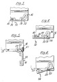
- Figures 3,4,5 and 6 are schematic top plan views showing the front wall in the closed and latched position, the closed and unlatched position, the open position and in a position prior to latching, respectively.
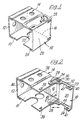
- the support bracket illustrated in Figure 1 can be seen to comprise an open sided box structure having a bottom wall 10, a rear wall 12, a top wall 14, and a side wall 16, which are all rigidly connected to one another and are preferably formed as a one-piece metal stamping.
- the front of the open box structure is closed by a front wall 18.
- This front wall is shown as comprising a plastics material, preferably polypropylene, transparent material wall having a main wall portion 20 and top and bottom flanges 22 and 24.
- top, rear and bottom walls are provided with apertures or notches, one of which is indicated by the reference numeral 26, to enable the bracket to be secured to a wall or roof structure.
- the front wall 18 is pivotally mounted on the top and bottom walls by a hinge connection.
- this hinge connection comprises a hinge pin 28, 29 on the top and bottom walls 14 and 10, respectively.
- the top and bottom flanges 22 and 24 are provided with a cooperating guide aperture or slot 30 which has a first arm 32 projecting along the length of the top or bottom and providing a first guide surface and a second arm 34 angled with respect thereto to provide a second guide surface at approximately 90° to the first, the two arms meeting at a curved junction 36.
- the side of the aperture opposite the first and second guide surfaces forms a third, curved guide surface extending between their outer ends. This, in effect, constitutes a concave 'hypotenuse' of the right angled triangle defined by the first and second guide surfaces.
- top and bottom walls have a ramp-like latching projection 38, 39 punched out of them respectively, these being located at the left-hand end, remote from the pivot pins 28 and 29, respectively.
- the top and bottom flanges have cooperating apertures 40 and 41 and generally square shaped notches 42, 44 which are open at the rear edge of the top and bottom flanges respectively.
- edge 47 could engage an offset portion on the top or bottom wall, which causes the front wall to pivot automatically as if it had pressed against the front of a headrail, with the hinge pin 28 moving continuously along the first and second guide surfaces.
- the outer surface of the main part 20 of the front wall 18 will be adjacent to the inner surface of the side wall and usually between the end of the headrail and the side wall.
- the front wall is formed of a transparent plastics material if a coloured head-rail is used, as is now quite common, the colour will appear through the transparent front wall, so that the bracket will not appear unsightly.
Landscapes
- Engineering & Computer Science (AREA)
- Structural Engineering (AREA)
- Architecture (AREA)
- Civil Engineering (AREA)
- Blinds (AREA)
Claims (9)
Applications Claiming Priority (2)
| Application Number | Priority Date | Filing Date | Title |
|---|---|---|---|
| GB8308640 | 1983-03-29 | ||
| GB08308640A GB2137270B (en) | 1983-03-29 | 1983-03-29 | A support bracket for a venetian blind headrail |
Publications (3)
| Publication Number | Publication Date |
|---|---|
| EP0121307A2 EP0121307A2 (de) | 1984-10-10 |
| EP0121307A3 EP0121307A3 (en) | 1986-02-12 |
| EP0121307B1 true EP0121307B1 (de) | 1988-07-20 |
Family
ID=10540420
Family Applications (1)
| Application Number | Title | Priority Date | Filing Date |
|---|---|---|---|
| EP84300894A Expired EP0121307B1 (de) | 1983-03-29 | 1984-02-13 | Halterung für die Kopfschiene einer Lamellenjalousie |
Country Status (5)
| Country | Link |
|---|---|
| US (1) | US4580753A (de) |
| EP (1) | EP0121307B1 (de) |
| CA (1) | CA1198666A (de) |
| DE (1) | DE3472815D1 (de) |
| GB (1) | GB2137270B (de) |
Families Citing this family (18)
| Publication number | Priority date | Publication date | Assignee | Title |
|---|---|---|---|---|
| US4824062A (en) * | 1988-08-25 | 1989-04-25 | Graber Industries, Inc. | Curtain rod and end bracket assembly |
| US4938443A (en) * | 1988-12-02 | 1990-07-03 | Carey-Mcfall Corporation | Venetian blind installation bracket |
| GB8920965D0 (en) * | 1989-09-15 | 1989-11-01 | Hallis Hudson Group Limited | A mounting bracket |
| US5143336A (en) * | 1990-11-26 | 1992-09-01 | Kenney Manufacturing Company | Curtain rod mounting assembly |
| US5265837A (en) * | 1992-06-19 | 1993-11-30 | Norbert Marocco | End support for window covering assembly |
| US6382295B1 (en) * | 1997-04-17 | 2002-05-07 | Jerome Nicholson | Mini-blind/curtain rod bracket |
| US6279863B1 (en) * | 2000-06-22 | 2001-08-28 | Richard D. Hall | Removable blind hanger brackets |
| US6668899B1 (en) | 2001-08-13 | 2003-12-30 | Thomas A. Thomas, Jr. | Laterally moving supports for horizontal blinds |
| DE20117159U1 (de) | 2001-10-16 | 2002-02-14 | C. & E. Fein GmbH & Co KG, 70176 Stuttgart | Werkzeugmaschine mit Befestigungsflansch |
| KR20040047246A (ko) * | 2002-11-29 | 2004-06-05 | 송명호 | 블라인드 프레임의 지지브라켓 체결구조 |
| USD482223S1 (en) | 2002-07-29 | 2003-11-18 | Kenney Manufacturing Co. | Head rail mounting clip |
| US7637302B2 (en) * | 2005-06-30 | 2009-12-29 | Hunter Douglas Inc. | Lock lever mounting bracket for headrails on coverings for architectural openings |
| US7516771B2 (en) * | 2005-06-30 | 2009-04-14 | Hunter Douglas Inc. | Lock lever mounting bracket for headrails on coverings for architectural openings |
| US8201789B1 (en) * | 2011-01-27 | 2012-06-19 | Tser Wen Chou | Blind support for installation of a blind rail |
| US8210504B1 (en) * | 2011-05-19 | 2012-07-03 | Skornickel Anthony J | Fence rail hanger bracket |
| US20130008616A1 (en) * | 2011-07-06 | 2013-01-10 | Ching Feng Home Fashions Co., Ltd. | Cordless window curtain |
| US10702086B1 (en) | 2020-01-17 | 2020-07-07 | King Saud University | Curtain rod holder |
| USD1098889S1 (en) * | 2023-08-16 | 2025-10-21 | Conivate IP, Inc. | Bracket |
Family Cites Families (8)
| Publication number | Priority date | Publication date | Assignee | Title |
|---|---|---|---|---|
| US1431353A (en) * | 1920-09-22 | 1922-10-10 | Herbert James Preston | Supporting and holding bracket for curtain rods and the like |
| US2267160A (en) * | 1941-03-10 | 1941-12-23 | Kersch Company | Venetian blind bracket |
| US2526393A (en) * | 1946-06-04 | 1950-10-17 | Lorentzen Hardware Mfg Corp | Venetian blind bracket |
| GB619884A (en) * | 1947-08-27 | 1949-03-16 | Thomas Edward Blackburn | An improved hinge |
| US2680589A (en) * | 1949-08-30 | 1954-06-08 | Lorentzen Hardware Mfg Corp | Venetian blind installation bracket |
| US2792999A (en) * | 1953-11-02 | 1957-05-21 | Lorentzen Hardware Mfg Corp | Venetian blind installation bracket |
| US4177853A (en) * | 1977-05-19 | 1979-12-11 | International Blind Company | Venetian blind assembly and mounting means therefor |
| US4265423A (en) * | 1979-05-30 | 1981-05-05 | Hunter Douglas International N.V. | Support bracket for a venetian blind head rail |
-
1983
- 1983-03-29 GB GB08308640A patent/GB2137270B/en not_active Expired
-
1984
- 1984-02-13 DE DE8484300894T patent/DE3472815D1/de not_active Expired
- 1984-02-13 EP EP84300894A patent/EP0121307B1/de not_active Expired
- 1984-02-27 US US06/583,987 patent/US4580753A/en not_active Expired - Fee Related
- 1984-03-28 CA CA000450763A patent/CA1198666A/en not_active Expired
Also Published As
| Publication number | Publication date |
|---|---|
| DE3472815D1 (en) | 1988-08-25 |
| US4580753A (en) | 1986-04-08 |
| CA1198666A (en) | 1985-12-31 |
| EP0121307A3 (en) | 1986-02-12 |
| GB8308640D0 (en) | 1983-05-05 |
| GB2137270A (en) | 1984-10-03 |
| GB2137270B (en) | 1986-01-29 |
| EP0121307A2 (de) | 1984-10-10 |
Similar Documents
| Publication | Publication Date | Title |
|---|---|---|
| EP0121307B1 (de) | Halterung für die Kopfschiene einer Lamellenjalousie | |
| CA1163912A (en) | Support bracket for a venetian blind head rail | |
| US4099753A (en) | Automatic locking mechanism for one of a pair of hinged doors | |
| US5077864A (en) | Swing door hinge | |
| CA2050776A1 (en) | Friction stays | |
| GB2291678A (en) | Stay with catch | |
| US4222149A (en) | Door hinge arrangement permitting opening of the door alternatively at either side | |
| EP0551980B1 (de) | Verriegelung für eine angelenkte Platte | |
| US5018626A (en) | Curtain rod and end bracket assembly | |
| CA1094470A (en) | Hinge mounting means | |
| US5492381A (en) | Retractable door or window stop | |
| US5813533A (en) | Storage/display box for drill bits or the like | |
| US2230599A (en) | Locking device | |
| US5542212A (en) | locking terminal for full tilt double-hung windows | |
| CA1140618A (en) | Door latch | |
| GB2068451A (en) | Travel limiting devices | |
| US7243462B2 (en) | Access door | |
| US4134232A (en) | Animal door assembly | |
| JP3316721B2 (ja) | キャビネットのロック装置 | |
| US3091796A (en) | Door hinge and hold open | |
| US6094865A (en) | Shutter handle latch | |
| US2451798A (en) | Catch | |
| US3849835A (en) | Spring hinge for bifold doors | |
| US4357038A (en) | Doorcatch | |
| JP2969498B2 (ja) | すべり出し窓 |
Legal Events
| Date | Code | Title | Description |
|---|---|---|---|
| PUAI | Public reference made under article 153(3) epc to a published international application that has entered the european phase |
Free format text: ORIGINAL CODE: 0009012 |
|
| AK | Designated contracting states |
Designated state(s): DE FR IT SE |
|
| PUAL | Search report despatched |
Free format text: ORIGINAL CODE: 0009013 |
|
| AK | Designated contracting states |
Designated state(s): DE FR IT SE |
|
| 17P | Request for examination filed |
Effective date: 19860403 |
|
| 17Q | First examination report despatched |
Effective date: 19870318 |
|
| GRAA | (expected) grant |
Free format text: ORIGINAL CODE: 0009210 |
|
| AK | Designated contracting states |
Kind code of ref document: B1 Designated state(s): DE FR IT SE |
|
| ITF | It: translation for a ep patent filed | ||
| REF | Corresponds to: |
Ref document number: 3472815 Country of ref document: DE Date of ref document: 19880825 |
|
| ET | Fr: translation filed | ||
| PGFP | Annual fee paid to national office [announced via postgrant information from national office to epo] |
Ref country code: SE Payment date: 19890203 Year of fee payment: 6 |
|
| PGFP | Annual fee paid to national office [announced via postgrant information from national office to epo] |
Ref country code: FR Payment date: 19890209 Year of fee payment: 6 |
|
| ITTA | It: last paid annual fee | ||
| PGFP | Annual fee paid to national office [announced via postgrant information from national office to epo] |
Ref country code: DE Payment date: 19890323 Year of fee payment: 6 |
|
| PLBE | No opposition filed within time limit |
Free format text: ORIGINAL CODE: 0009261 |
|
| STAA | Information on the status of an ep patent application or granted ep patent |
Free format text: STATUS: NO OPPOSITION FILED WITHIN TIME LIMIT |
|
| 26N | No opposition filed | ||
| PG25 | Lapsed in a contracting state [announced via postgrant information from national office to epo] |
Ref country code: SE Effective date: 19900214 |
|
| PG25 | Lapsed in a contracting state [announced via postgrant information from national office to epo] |
Ref country code: FR Effective date: 19901031 |
|
| PG25 | Lapsed in a contracting state [announced via postgrant information from national office to epo] |
Ref country code: DE Effective date: 19901101 |
|
| REG | Reference to a national code |
Ref country code: FR Ref legal event code: ST |
|
| EUG | Se: european patent has lapsed |
Ref document number: 84300894.7 Effective date: 19901107 |