EP0121409A2 - Dispositif pour empiler des feuilles - Google Patents
Dispositif pour empiler des feuilles Download PDFInfo
- Publication number
- EP0121409A2 EP0121409A2 EP84302120A EP84302120A EP0121409A2 EP 0121409 A2 EP0121409 A2 EP 0121409A2 EP 84302120 A EP84302120 A EP 84302120A EP 84302120 A EP84302120 A EP 84302120A EP 0121409 A2 EP0121409 A2 EP 0121409A2
- Authority
- EP
- European Patent Office
- Prior art keywords
- paper sheets
- separator
- blade wheel
- receiving
- paper
- Prior art date
- Legal status (The legal status is an assumption and is not a legal conclusion. Google has not performed a legal analysis and makes no representation as to the accuracy of the status listed.)
- Granted
Links
- 230000007246 mechanism Effects 0.000 claims description 16
- 238000012546 transfer Methods 0.000 claims description 5
- 230000003287 optical effect Effects 0.000 description 15
- 230000002093 peripheral effect Effects 0.000 description 8
- 238000012545 processing Methods 0.000 description 6
- 238000010009 beating Methods 0.000 description 4
- 238000010586 diagram Methods 0.000 description 4
- 238000000034 method Methods 0.000 description 3
- 230000008569 process Effects 0.000 description 3
- 238000010276 construction Methods 0.000 description 2
- 230000008878 coupling Effects 0.000 description 2
- 238000010168 coupling process Methods 0.000 description 2
- 238000005859 coupling reaction Methods 0.000 description 2
- 230000003111 delayed effect Effects 0.000 description 2
- 230000000903 blocking effect Effects 0.000 description 1
- 230000002542 deteriorative effect Effects 0.000 description 1
- 238000011161 development Methods 0.000 description 1
- 230000004048 modification Effects 0.000 description 1
- 238000012986 modification Methods 0.000 description 1
- 230000009467 reduction Effects 0.000 description 1
- 230000004044 response Effects 0.000 description 1
Images






Classifications
-
- B—PERFORMING OPERATIONS; TRANSPORTING
- B65—CONVEYING; PACKING; STORING; HANDLING THIN OR FILAMENTARY MATERIAL
- B65H—HANDLING THIN OR FILAMENTARY MATERIAL, e.g. SHEETS, WEBS, CABLES
- B65H31/00—Pile receivers
- B65H31/32—Auxiliary devices for receiving articles during removal of a completed pile
-
- B—PERFORMING OPERATIONS; TRANSPORTING
- B65—CONVEYING; PACKING; STORING; HANDLING THIN OR FILAMENTARY MATERIAL
- B65H—HANDLING THIN OR FILAMENTARY MATERIAL, e.g. SHEETS, WEBS, CABLES
- B65H29/00—Delivering or advancing articles from machines; Advancing articles to or into piles
- B65H29/38—Delivering or advancing articles from machines; Advancing articles to or into piles by movable piling or advancing arms, frames, plates, or like members with which the articles are maintained in face contact
- B65H29/40—Members rotated about an axis perpendicular to direction of article movement, e.g. star-wheels formed by S-shaped members
-
- B—PERFORMING OPERATIONS; TRANSPORTING
- B65—CONVEYING; PACKING; STORING; HANDLING THIN OR FILAMENTARY MATERIAL
- B65H—HANDLING THIN OR FILAMENTARY MATERIAL, e.g. SHEETS, WEBS, CABLES
- B65H31/00—Pile receivers
- B65H31/30—Arrangements for removing completed piles
- B65H31/3054—Arrangements for removing completed piles by moving the surface supporting the lowermost article of the pile, e.g. by using belts or rollers
-
- B—PERFORMING OPERATIONS; TRANSPORTING
- B65—CONVEYING; PACKING; STORING; HANDLING THIN OR FILAMENTARY MATERIAL
- B65H—HANDLING THIN OR FILAMENTARY MATERIAL, e.g. SHEETS, WEBS, CABLES
- B65H2301/00—Handling processes for sheets or webs
- B65H2301/40—Type of handling process
- B65H2301/42—Piling, depiling, handling piles
- B65H2301/421—Forming a pile
- B65H2301/4212—Forming a pile of articles substantially horizontal
-
- B—PERFORMING OPERATIONS; TRANSPORTING
- B65—CONVEYING; PACKING; STORING; HANDLING THIN OR FILAMENTARY MATERIAL
- B65H—HANDLING THIN OR FILAMENTARY MATERIAL, e.g. SHEETS, WEBS, CABLES
- B65H2301/00—Handling processes for sheets or webs
- B65H2301/40—Type of handling process
- B65H2301/42—Piling, depiling, handling piles
- B65H2301/426—Forming batches
-
- B—PERFORMING OPERATIONS; TRANSPORTING
- B65—CONVEYING; PACKING; STORING; HANDLING THIN OR FILAMENTARY MATERIAL
- B65H—HANDLING THIN OR FILAMENTARY MATERIAL, e.g. SHEETS, WEBS, CABLES
- B65H2701/00—Handled material; Storage means
- B65H2701/10—Handled articles or webs
- B65H2701/19—Specific article or web
- B65H2701/1912—Banknotes, bills and cheques or the like
Definitions
- the present invention relates to a paper sheet stacking apparatus for dividing continuously fed paper sheets into regular sheaves each consisting of a predetermined number of paper sheets, which comprises a blade wheel means rotating about a substantially horizontal axis of rotation, the vane wheel means having a plurality of blades extending from the central portion to the outer periphery thereof in the direction opposite to the rotating direction thereof, each two adjacent blades defining therebetween a space having an opening on the outer periphery of the blade wheel means, feeding means for continuously inserting the paper sheets into the spaces, one for each space, through the openings of the blade wheel means passing a predetermined receiving position, a stationary stop adapted to abut against the paper sheets held in the spaces and rotating together with the blade wheel means, thereby stopping the rotaton of the paper sheets, so that the paper sheets are discharged from the spaces of the vane wheel means and dropped automatically, and main stacking means for receiving and bearing thereon the paper sheets discharged from the blade wheel means.
- Paper sheet stacking apparatuses of this type are generally known. Paper sheets or documents, such as bank notes, data cards, printed matter, etc., are conventionally processed in a mechanized system. Since these documents have recently been increasing steadily, there is an urgent demand for the development of high-speed processing apparatuses for them.
- processing of bank notes includes a step of tying them up with bands or the like into bundles each consisting of a predetermined number of bank notes.
- the paper sheets are divided into regular sheaves each including a predetermined number of sheets on an automatic processing apparatus, and the sheaves are then tied up with bands.
- Such an automatic processing apparatus is preferably constructed so that the paper sheets fed one by one at high speed can continuously be stacked without interrupting the feed of the paper sheets, and that the division into the regular sheaves is achieved in the course of the stacking process.
- Conventional paper sheet stacking means to fulfill these requirements include the so-called beating system, in which the paper sheets delivered from the delivery- side end of conveyor means and flying in the air are beaten down.
- this stacking means there is a limit to the high-speed response characteristic of direction changing means for the sheet papers. Since the cycle of the direction changing means is raised by high-speed vibration with constant amplitude, so the force of inertia is increased. Thus, the operation of the direction changing means becomes unstable, or the force applied to the mechanical part is increased. To cope with this, the apparatus is increased in size and therefore in cost.
- the beating system moreover, the force used in beating the paper sheets is so great that some of the paper sheets may be stacked in folded or torn states. Consequently, the beating system is not a suitable system for high-speed paper sheet stacking.
- the blade wheel has a plurality of elongate blades extending from the central portion of the blade wheel in the direction opposite to the rotating direction and arranged along the circumference of the blade wheel. Paper sheets are fed into slender spaces formed between the blades of the blade wheel, rotated together with the blade wheel through a predetermined angle, and then discharged from the blade wheel at a predetermined position to be stacked in place.
- N the number of the paper sheets per minute successively inserted into the slender spaces
- n N/m RPM , where m is the number of the spaces.
- the rotary speed n of the blade wheel is obtained by dividing the number of paper sheets to be fed per minute by the number of the spaces. This implies that the blade wheel is rotated relatively slowly. Even in a case such that, for example, 1,800 paper sheets are supplied every minute to the blade wheel, the rotary speed n of the blade wheel may be as low as 100 (rpm) if the spaces used are 18 in number. Accordingly, the blade wheel need not be rotated at high speed, and hence will not cause any trouble in high-speed paper sheet processing.
- Paper sheet stacking apparatuses have conventionally been proposed which combine the stacking means using the blade wheel with dividing means capable of dividing paper sheets into regular sheaves without interrupting the feed of the paper sheets.
- An example of such apparatuses is disclosed in Japanese Patent Application No. 26369/81.
- This apparatus is provided with a separator which includes an arm portion having an axis of rotation substantially in alignment with that of the blade wheel and extending from the axis to a position beyond the peripheral edge of the blade wheel along the side face thereof, and a receiving portion at the distal end of the arm portion.
- the separator is rotated as required, paper sheets held individually in spaces of the blade wheel abut against the arm portion to be removed from the spaces.
- the removed paper sheets are temporarily held by the receiving portion.
- paper sheets previously removed by a stationary-stop-end stacked-on stacking means are delivered. Thereafter, the paper sheets on the receiving portion of the separator are transferred to the stacking means.
- the conventional paper sheet stacking apparatus combining the blade-wheel stacking means and dividing means have the following problems.
- the arm portion of the separator In temporarily receiving the paper sheets following a predetermined number of sheets by means of the separator, the arm portion of the separator is used as a stop for removing the aforesaid paper sheets from the spaces of the blade wheel, and the removed paper sheets are held by the receiving portion. Therefore, the arm portion is naturally located within the range of the width (along the axis of rotation of the blade wheel) of the paper sheets in the spaces of the blade wheel. Accordingly, when the separator is located in the section between the position for the feed of the paper sheets into the blade wheel and the position for the start of division or receiving, the depth of the spaces of the blade wheel is practically reduced by the existence of the arm portion.
- the rear edge portions of those paper sheets which are fed into the blade wheel while the separator is in the aforesaid intermediate section project from the spaces.
- the projecting portions will close the opening of each following space to receive the next paper sheet, thereby preventing the following paper sheet from entering its corresponding space.
- the rejected paper sheet will run against the one blocking its entrance and cause a jam.
- the interval of feed of the paper sheets into the blade wheel is inevitably lengthened, so that it is impossible to speed up the paper sheet processing.
- the division of the paper sheets into the regular sheaves in stacking requires the separator to be rotated intermittently. The intermittent drive of the separator requires great power, so that the conventional stacking apparatus is high in power consumption.
- the present invention is contrived in consideration of these circumstances, and is intended to provide a paper sheet stacking apparatus capable of uninterruptedly dividing paper sheets fed one by one at regular intervals into regular sheaves, each consisting of a predetermined number of sheets, without deteriorating the high-speed performance innate in a blade wheel stacking system, and reduced in power consumption for the division.
- a paper sheet stacking apparatus is provided with separator means rotatably supported in substantially coaxial relation with blade wheel means and capable of receiving dropped paper sheets; the separator means having an arm portion extending in the radial direction of the blade wheel means to a position beyond the outer periphery of the blade wheel means via the side of paper sheets held in the blade wheel means; and a receiving portion for receiving the dropped paper sheets, the paper sheets dropped from the blade wheel means being adapted to be stacked on the receiving portion when the separator means is brought close to the blade wheel means and is rotated to reach a receiving position where the receiving portion receives the dropped paper sheets; a rotating mechanism for rotating the separator means; a linear drive mechanism for moving the separator means toward the axis of rotation of the blade wheel means; auxiliary stacking means for transferring the paper sheets on the receiving portion of the separator means to main stacking means; and control means adapted to rotate the separator means located in the position close to the blade wheel means and stopping in a stand-by position beyond
- the paper sheets fed into the blade wheel means will never be touched by the arm portion of the separator wherever the separator is located. Accordingly, the paper sheets can always be inserted quickly and fully into spaces of the blade wheel means. It is therefore unnecessary to secure long feed intervals for the paper sheets that are required by the prior art apparatuses.
- the paper sheets can be divided into the regular sheaves in a manner such that the innate high-speed performance of the blade-wheel stacking system is best exhibited. For intermittent dividing operation of the separator, it is necessary to locate the separator in the receiving position at the time of division, and in the stand-by position in other cases.
- the separator when the dividing operation is ended, the separator is retreated in the axial direction and rotated to the position beside the stand-by position, and is then advanced to the stand-by position. Without regard to the construction of the feeding means, therefore, the separator can be transferred from the receiving position to the stand-by position.
- the separator of the invention can be moved slowly to the stand-by position. This leads to a reduction in power consumption required for the transfer of the separator to the stand-by position.
- Fig. 1 is a side view, partially in section, showing a stacking apparatus according to the one embodiment of the invention
- Fig. 2 is a sectional view taken along line II-II of Fig. 1.
- numeral 1 designates a base plate positioned vertically.
- a parallel pair of support plates 2a and 2b are arranged at a predetermined space on one side of the base plate 1, extending parallel thereto.
- the support plates 2a and 2b are fixed at the lower portion thereof to the base plate 1 by means of a support member 3.
- Each of the support plates 2a and 2b is formed so that the lower portion of its left end face (in Fig. 1) constitutes a vertical surface 2c.
- Bearings 3a and 3b are coaxially buried in the upper portions of the support plates 2a and 2b, respectively.
- the axis of the bearings 3a and 3b extends at right angles to the lateral face of the base plate 1.
- a shaft 4 is rotatably supported by the inner peripheral edges of the bearings 3a and 3b.
- a pulley 5 is fixed on the shaft 4 (Fig. 2), positioned between the support plates 2a and 2b.
- One end side of an endless belt 6 is passed around the pulley 5, while the other end side is coupled to a drive source (not shown).
- the shaft 4 is rotated in the direction of an arrow 140 around the axis of rotation X-X (Fig. 2) at constant speed.
- a pair of blade wheels 9a and 9b for paper sheet stacking are coaxially fixed individually to both end portions of the shaft 4 by means of their corresponding sets of fixtures 7 and 8.
- the distance between the blade wheels 9a and 9b is shorter than the width W of paper sheets P to be stacked.
- a plurality of elongate blades 10, which extend outward from the central portion of the blade wheel 9b (9a) in the direction opposite to the rotating direction thereof, describing e.g., an involute curve, are arranged along the circumference of the blade wheel 9b (9a) with slender spaces 11 between them.
- the blade wheels 9a and 9b are fixed individually to the shaft 4 in a manner such that their slender spaces 11 are aligned along the shaft 4.
- a pulse motor 13 is provided on the side of the base plate 1 so that its drive shaft 14 is coaxial with the shaft 4.
- the pulse motor 13 is supported by a support member 15.
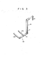
- a separator 16 is fixed to the drive shaft 14 of the pulse motor 16. As shown in Figs.
- the separator 16 is formed of an arm portion 17 which extends radially from the drive shaft 14 in parallel with the outer face of the blade sheet 9a, going beyond the outer peripheral edges of the blade wheels 9a and 9b, a bottom portion 18 which extends parallel to the shaft 4 from the distal end of the arm portion 17 toward the blade wheels 9a and 9b, and a receiving portion 20 consisting of two extending portions 19a and 19b which extend from the bottom portion 18 over a distance substantially half the length of the paper sheets P at substantially right angles to both the arm portion 17 and the bottom portion 18 and in the direction opposite to the rotating direction of the blade wheels 9a and 9b.
- a receiving portion 20 consisting of two extending portions 19a and 19b which extend from the bottom portion 18 over a distance substantially half the length of the paper sheets P at substantially right angles to both the arm portion 17 and the bottom portion 18 and in the direction opposite to the rotating direction of the blade wheels 9a and 9b.
- the support member 15 is supported by a nut 22 which is fitted on a screw rod 21 extending along a line parallel to the shaft 4.
- the screw rod 21 is rotatably supported at each end on support frames 24a and 24b by means of bearings 23a and 23b.
- the support frames 24a and 24b are fixed to the base plate 1 by means of support frames 25a and 25b.
- One end of the screw rod 21 is coupled to the drive shaft of a motor 26, which is fixed on the outer face of the support frame 24a.
- feeding means or a belt mechanism 31 for feeding the paper sheets P into the spaces 11 of the blade wheels 9a and 9b is provided between the top portions of the blade wheels 9a and 9b.
- the belt mechanism 31 is mainly composed of a pulley 32 disposed between the blade wheels 9a and 9b with its axis parallel to the shaft 4 (Fig. 2); lower belts 34 passed around the pulley 32 in two rows that are arranged at right angles to the drawing plane of Fig.
- the pulley 32 adapted to be driven in the direction of an arrow 33 by the pulley 32; upper belts 36 overlapping the top surfaces of the lower belts 34 up to the position of the pulley 32 and adapted to be guided in the direction of an arrow 35 to carry the paper sheets P at a section 30 wherein the belts 34 and 36 overlap one another; and a pulley 37 whereby the upper belts 36 are turned at a point beyond the pulley 32 on the extension of the section 30.
- the terminal end of the overlap section 30, that is, an outlet 30a for the paper sheets P is located inside the outer peripheral edges of the blade wheels 9a and 9b.
- the pulleys 32 and 37 are supported on the base plate 1 by means of support members (not shown).
- the lower and upper belts 34 and 36 are driven at the same speed higher than the peripheral speed of the blade wheels 9a and 9b.
- a main stacking unit 41 is disposed under the blade wheels 9a and 9b.
- the main stacking unit 41 comprises bearings 42a and 42b coaxially buried in the lower portions of the support plates 2a and 2b, respectively, arranged on a line parallel to the shaft 4; a shaft 43 rotatably supported by the inner rings of the bearings 42a and 42b; pulleys 44a, 44b and 44c fixed on the shaft 43; a set of belts including bets 45a, 45b and 45c passed around the pulleys 44a, 44b and 44c, respectively, and extending horizontally to the left of Fig. 1; and a motor (not shown) for driving these belts in the manner mentioned later.
- the auxiliary stacking unit 51 is disposed beside the main stacking unit 41.
- the auxiliary stacking unit 51 comprises support arms 52a, 52b, 52c and 52d (Fig. 2) extending substantially parallel to the belts 45a, 45b and 45c from the side of the support plates 2a and 2b and turned up and folded back downwardly so that its extreme end portion is located on the side of the support plates 2a and 2b, as shown in Fig.
- a coupling member (not shown) coupling the bottom portions of these support arms in a roundabout manner; a guide bar 54 for vertically guiding an end portion 53 on the side of the support plate 2b at the bottom portion of the support arm 52b, a belt 55 supported by a pair of pulleys 56 and coupled to the end portion 53, whereby the end portion 53 is moved up and down along the guide bar 54 to move all the support arms 52a to 52d vertically; and a motor (not shown) for driving the belt 55 in the manner mentioned later.
- a bar 61 for detecting the position of the separator 16 is fixed to the proximal portion of the drive shaft 14 of the pulse motor 13.
- the bar 61 has a circumferential width narrower than that of the arm portion 17 of the separator 16, and is fixed to the drive shaft 14 so as to extend in the same direction as the arm portion 17.
- Separator detectors 62a and 62b for detecting the existence of the bar 61 in an uncontacted manner are fixed to the side face of the pulse motor 13.
- the separator detectors 62a and 62b are each formed of a photocoupler including a light emitting element 63 and a light receiving element 64 which face in alignment with each other.
- the photocoupler delivers a low-level output signal when light incident on the light receiving element 64 is intercepted by the bar 61 interposed between the two elements 63 and 64. In other situations, the photocoupler delivers a high-level output signal.
- the separator detector 62a is located in a position B indicated by a broken line. The separator detector 62a delivers a low-level output signal when the bar 61 or the arm portion 17 of the separator 16 reaches the position B.
- the separator detector 62b is attached to a position C indicated by a broken-line circle, and delivers a low-level signal when the arm portion 17 of the separator 16 reaches the position C.
- a depression 65 (Fig.
- a pulse generator 66 for generating pulses in synchronism with the rotation of - the blade wheels 9a and 9b is fitted in the depression 65.
- the pulse generator 66 is mainly composed of a photocoupler which includes a light emitting element 67 for projecting light at a given angle on the inner face of the blade wheel 9a, and a light receiving element 68 for receiving reflected light from the inner face of the blade wheel 9a.
- the depression 65 is omitted for the simplicity of illustration. As shown in Fig.
- a plurality of perforations 69 are circumferentially arranged in that portion of the blade wheel 9a which receives the projected light.
- the individual perforations 69 are located on lines which connect the center 70 of the blade wheel 9a and the tips Q of their corresponding blades 10.
- the pulse generator 66 delivers an output pulse when the light from the light emitting element 67 has passed through the perforations 69 and there is no reflected light to be projected on the light receiving element 68.
- a sheet number detector 73 is disposed at that portion of the overlap section 30 of the belt mechanism 31 near the paper outlet 30a. The sheet number detector 73 detects the paper sheets P passing between the lower and upper belts 34 and 36 of the belt mechanism 31, and delivers an output pulse when a predetermined number of paper.
- the principal part of the sheet number detector 73 is formed of a light emitting element 74 and a light receiving element 75, which vertically face each other with the overlap section 30 of the belt mechanism 31 therebetween, and are located halfway between each parallel pair of belts 34 or 36.
- a stacking detector 77 is disposed beside the main stacking unit 41.
- the stacking detector 77 includes a light emitting element 78 and a light receiving element 79 facing each other on an oblique optical axis which extends within a plane between the belts 45b and 45c substantially at a right angle to the shaft 4 and is declined to the right of Fig. 1.
- the detector 77 delivers an output signal when the light receiving element 79 receives light emitted from the light emitting element 78.
- an upper detector 80 and a lower detector 81 are for detecting the respective upper and lower positions of the support arms 52a, 52b, 52c and 52d.
- the upper and lower detectors 80 and 81 are each formed of a photocoupler, and delivers low-level outputs when a bar 82 protruding from the end portion 53 of the support arm 52b intercepts the optical path. In other situations, the detectors 80 and 81 deliver high-level outpus signals. When the output of the upper or lower detector 80 or 81 goes low, the support arms 52a to 52d are brought to the height mentioned later.
- Detectors 84 and 85 for detecting the position of the nut 22 are provided beside the screw rod 21 (Fig. 2). For convenience, the detectors 84 and 85 will hereinafter be referred to as left and right detectors, respectively.
- the left and right detectors 84 and 85 are each formed of a photocoupler, and deliver low-level outputs when a lever 86 protruding from the nut 22 intercepts the optical path. In other situations, the detectors 84 and 85 deliver high-level outputs.
- the receiving portion 20 of the separator 16 is located outside the outer peripheral edges of the blade wheels 9a and 9b and in the most deeply overlapped relation as viewed along the axis of the blade wheels 9a and 9b, while the arm portion 17 is located off and outside the facing side edges of the paper sheets P held in the spaces 11.
- the receiving portion 20 When the optical path of the right detector 85 is intercepted by the bar 86, on the other hand, the receiving portion 20 is located in its right end position, as in Fig. 2, farthest from the outer peripheral edges of the blade wheels 9a and 9b. In this state, as described later, the receiving portion 20 never prevents the paper sheets P from being forced out and dropped freely from the blade wheels 9a and 9b.
- the outputs El and E2 of the separator detectors 62a and 62b (Fig. 4), output F of the pulse generator 66 (Fig. 5), output J of the sheet number detector 73 (Fig. 1) , output H of the stacking detector 77 (Fig. 1), outputs Kl and K2 of the upper and lower detectors 80 and 81 (Fig. 1), and outputs Ml and M2 of the left and right detectors 84 and 85 (Fig. 2) are supplied to a control unit 91. As shown in Fig. 7, the control unit 91 has nine input terminals 92 to 100. The output El of the separator detector 62a is applied to the input terminal 92; and is then fed to one input terminal of an AND gate 101.
- the output J of the sheet number detector 73 is applied to the input terminal 93, and is then fed to one input terminal of an AND gate 104 through a delay circuit 102 set to the delay time mentioned later and a one-shot multivibrator 103.
- the output F of the pulse generator 66 is applied to the input terminal 94, and is then fed to the other input terminal of the AND gate 104.
- the output of the AND gate 104 is supplied to the other input terminal of the AND gate 101 through a one-shot multivibrator 105.
- the outputs E2 and Ml of the separator detector 62b and the left detector 84 are applied to the input terminals 95 and 96, respectively, and are then supplied to the first and second input terminals of an AND gate 106.
- the output H of the stacking detector 77 is applied to the input terminal 97.
- the output H and a signal E1, obtained by inverting the output El by an inverter 107, are fed to an AND gate 108.
- the output of the AND gate 108 is supplied to one input terminal of an AND gate 110 through a one shot multivibrator 109.
- the output K1 of the upper detector 80 is applied to the input terminal 98, and is then fed to the other input terminal of the AND gate 110 and also to one input terminal of an AND gate 112 through an inverter 111.
- the output K2 of the lower detector 81 is applied to the input terminal 99, and is then fed to an AND gate 113.
- the output M2 of the right detector 85 is applied to the input terminal 100, and is then fed to the other input terminal of the AND gate 112. Further, a signal M2 obtained by inverting the output M2 by an inverter 114 is supplied to the other input terminal of the AND gate 113 and a third input terminal of the AND gate 106. The output M l and a signal E2, obtained by inverting the output E2 by an inverter 115, are fed to an AND gate 117.
- the control unit 91 comprises a pulse generator 118 for delivering a pulse output with the period mentioned later.
- the output terminal of the pulse generator 118 is connected to a forward rotation control terminal 122 and a reverse rotation control terminal 123 of a drive circuit 121 for driving the pulse motor 13 through transistors 119 and 120, respectively.
- the outputs of the AND gates 101 and 106 are supplied to the bases of the transistors 119 and 120, respectively.
- the output of the AND gate 110 is supplied to a forward rotation control terminal 126 of a drive circuit 125 for a motor 124 for driving the belt 55 of the auxiliary stacking unit 51.
- the output of the AND gate 113 is supplied to a reverse rotation control terminal 127 of the drive circuit 125.
- the output of the ANd gate 112 is fed to a forward rotation control terminal 129 of a drive circuit 128 for the motor 26, while the output of the AND gate 117 is applied to a reverse rotation control terminal 130 of the circuit 128.
- the output of the inverter 107 is supplied through a delay circuit 131 to a differentiating circuit 132 for differentiating the rise of the output of the delay circuit 131.
- the output of the differentiating circuit 132 is supplied as a drive signal to a one-shot multivibrator 133, whose output is supplied as a control signal to a drive circuit 135 for a motor 134 for driving the belts 45a, 45b and 45c of the stacking unit 41.
- the running speed of the belt mechanism 31 and the speed of feeding of the paper sheets P to the mechanism 31 are set so that the time interval, which elapses from the instant that the forward edge of one paper sheet P carried by the belt mechanism 31 passes a certain spot until the forward edge of a subsequent paper sheet P reaches that spot, is 50 milliseconds.
- the time interval, which elapses from the instant that the backward edge of the first paper sheet P passes the predetermined spot until the forward edge of the second paper sheet P reaches the spot is 25 milliseconds.
- the rotational frequency of the blade wheels 9a and 9b is set as follows.
- the rotation angle a for each space 11 is 30°. Therefore, it is necessary only that the blade wheels 9a and 9b rotate through an angle of 30° in 50 miliseconds.
- the rotary speed n of the blade wheels 9a and 9b is set to 100 rpm.
- the drive source (not shown) rotates the blade wheels 9a and 9b in the direction of the arrow 140 of Fig. 1 at 100 rpm, and drives the belts 34 and 36 in the directions of the arrows 33 and 35, respectively, in compliance with the aforesaid conditions.
- the support arms 52a to 52d (only 52d is illustrated) of the auxiliary stacking unit 51 are located below the upper path portions of the belts 45a, 45b and 45c (only 45c is illustrated), as shown in Figs. 1 and 9, i.e., the bar 82 is at the height to intercept the optical path of the lower detector 81 (Fig. 1), and that the separator 16 is located in the position shown in Figs. 9 and 10, i.e., the optical paths of the left detector 84 and the upper separator detector 62b are intercepted by the bars 86 and 61, respectively. In the position shown in Figs.
- the arm portion 17 of the separator 16 extends substantially vertically upward, so that the separator 16 prevents neither the supply of the paper sheets P to the blade wheels 9a and 9b nor the natural or automatic dropping of the paper sheets P discharged from the blade wheels 9a and 9b.
- This position will hereinafter be referred to as the stand-by position of the separator 16.
- the position of the left detector 84 and the axial position of the separator 16 have the aforesaid relationship, and the arm portion 17 of the separator 16 is located outside the facing side edges of the paper sheets P held in the spaces 11 of the blade wheels 9a and 9b.
- the separator 16 Since the receiving portion 20 is located beyond the outer peripheral edges of the blade wheels 9a and 9b, the separator 16 is kept from touching the paper sheets P, which are delivered from the paper outlet 30a (Fig. 1) of the belt mechanism 31 into the spaces 11 of the blade wheels 9a and 9b. Accordingly, the paper sheets P are allowed to enter the spaces 11 as if the separator 16 did not exist. Before the paper sheets P are entirely housed in the individual spaces 11, they are decelerated by a frictional force which depends on the shape and surface condition of the spaces 11. That position of the blade wheels 9a and 9b which provides a situation such that the opening 12 (Fig.
- each paper sheet P in each individual space 11 gradually comes out of the space 11 with its backward edge forward. After the whole body of the paper sheet P is removed from the space 11, the paper sheet P automatically falls in a substantially horizontal position onto the predetermined place of the belts 45a, 45b and 45c of the main stacking unit 41. Thus, a sheaf Po of paper sheets P is formed on the belts, rapidly increasing its thickness as a sheet is added thereto every 50 milliseconds.
- the optical path of the photocoupler constituting the upper separator detector 62b is intercepted by the bar 61, so that the output E2 of the separator detector 62b is maintained at the low level.
- the pulse generator 66 delivers the pulsating output F with a period of 50 milliseconds as the blade wheels 9a and 9b rotate.
- the output F is supplied to the AND gate 104.
- the outputs K2 and M l of the lower and left detectors 81 and 84 are maintained at the low level, and the outputs Kl and M 2 of the upper and right detectors 80 and 85 at the high level.
- the sheet number detector 73 delivers the pulsating output J.
- the predetermined number means the number of the paper sheets included in each regular sheaf.
- the output J is fed to one input terminal of the AND gate 104 through the delay circuit 102 and the one-shot multivibrator 103 of the control unit 91 shown in F ig. 7.
- a delay time Tl of the delay circuit 102 is set as follows.
- the delay time Tl is equivalent to the time interval which elapses from the time tl when the rear edge of the paper sheet Pl crosses the optical axis 73a of the sheet number detector 73 until the tip Q of the blade 10b directly before the space lla reaches the position just beside the center line R of the arm portion 17 of the separator 16 as viewed along the axis of the blade wheels 9a and 9b.
- the pulse generator 66 is actuated to deliver the output F every time the edge of a blade 10 of each of the blade wheels 9a and 9b crosses the center line R of the stopped separator 16.
- the AND gate 104 is simultaneously supplied at a time t2 with the pulsating signal F then delivered from the pulse generator 66 and a signal delivered from the sheet number detector 73.
- the signal from the detector 73 is delayed for the delay time Tl. Accordingly, the AND gate 104 is opened, so that the one-shot multivibrator 105 is driven.
- the output El of the separator detector 62a is at the high level, so that the AND gate 101 is opened to turn on the transistor 119.
- the output pulse of the pulse generator 118 (Fig. 7) is supplied as a forward rotation control signal to the drive circuit 121 via the transistor 119.
- the pulse motor 13 is rotated to rotate the separator 16 in the counterclockwise direction of Fig. 11 at the same speed as the blade wheels 9a and 9b.
- the blade wheels 9a and 9b and the separator 16 are rotated at the same speed because the pulse generators 118 and 66 are designed so as to deliver output pulses with the same period.
- the separator 16 rotates in the same direction and at the same speed as the blade wheels 9a and 9b with the center line R of its arm portion 17 positioned just beside the edge Q of the blade 10b on and after the time t2.
- the output El of the inverter 107 obtained by inverting the output El is switched to the high level.
- the output E1 is supplied to the delay circuit 131 and the differentiating circuit 132 for differentiating the rise of the output of the delay circuit 131.
- the output of the differentiating circuit 132 is supplied as a control signal to the drive circuit 135 for the motor 134 through the one-shot multivibrator 133.
- the motor 134 (Fig.
- a delay time T2 of the delay circuit 131 is adjusted to the time interval required for the 100th paper sheet P or the last one of paper sheets P constituting a sheaf to finish falling. During such a period, the paper sheets P continue to be stacked one after another on the receiving portion 20.
- the stacking detector 77 is actuated, that is, the output H of the detector 77 is switched to the high level.
- the output H is fed to the AND gate 108.
- the output El is at the low level, so that the output El of the inverter 107 is at the high level.
- the AND gate 108 is opened and the one-shot multivibrator 109 is driven.
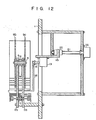
- the output Kl of the upper detector 80 is at the high level, so that the AND gate 110 is opened, and a forward rotation control signal is supplied to the drive circuit 125. Accordingly, the motor 124 rotates in the forward direction, so that the support arms 52a to 52d of the auxiliary stacking unit 51 are gradually forced up, as shown in Fig. 13.
- the optical path of the upper detector 80 is intercepted by the bar 82, so that the output Kl is switched to the low level. As a result, the AND gate 110 is closed.
- the motor 124 ceases to rotate. Since the support arms 52a to 52d are located above he receiving portion 20, as mentioned above, the paper sheets P having so far been supported by the receiving portion 20 are transferred to the support arms 52a and 52d. In other words, the support arms 52a to 52d bear the paper sheets P thereon in place of the receiving portion 20.
- the output Kl of the upper detector 80 is switched to the low level, moreover, the output Kl of the inverter 111 is switched to the high level.
- the output M2 of the right detector 85 is at the high level, so that the AND gate 112 is opened, allowing a forward rotation control signal to be supplied to the drive circuit 128.
- the motor 26 starts to rotate in the forward direction at the time t5, so that the separator 16 is moved to the right or away from the blade wheels 9a and 9b, as shown in Fig. 15.
- the output M2 of the right detector 85 is switched to the low level to close the AND gate 112.
- the motor 26 ceases to rotate. In this state, the receiving portion 20 of the separator 16 is entirely removed from the space under the blade wheels 9a and 9b, and is located in its right end position, as shown in Fig. 15.
- the AND gate 106 is opened to turn on the transistor 120, since the outputs E2 and Ml of the separator detector 62b and the left detector 84 are at the high level.
- the output of the pulse generator 118 is supplied to the reverse rotation control terminal 123 of the drive circuit 121 through the transistor 120.
- the pulse motor 13 starts to rotate in the reverse direction at the time t6, so that the separator 16 starts to rotate in the direction opposite to the rotating direction of the blade wheels 9a and 9b. It is to be understood that the separator 16 may alternatively be rotated in the same direction as the blade wheels 9a and 9b.
- the output E2 of the separator detector 62b is switched to the low level at the time t8
- the output E2 of the inverter 115 is switched to the high level.
- the output MI of the left detector 84 is at the high level, so that the AND gate 117 is opened, allowing a reverse rotation control signal to be supplied to the drive circuit 128.
- the motor 26 starts to rotate in the reverse direction at the time t8, so that the separator 16 starts to move gradually from the position shown in Fig. 16 to the left.
- the output Ml of the left detector 84 is switched to the low level.
- the motor 26 ceases to rotate, and the separator 16 is on stand-by. Thereafter, the above-mentioned sequence of operation is repeated, based on a point of time when the output J of the sheet number detector 73 like the signal delivered at the time tl, is supplied.
- the paper sheets P that the continuously fed one by one are securely divided into regular sheaves of 100 sheets, which are fed one after another into an apparatus provided in the next stage.
- the arm portion 17 of the separator 16 is located in the position where it can never touch the paper sheets P, that is, the position outside the facing side edges of the paper sheets P held in the spaces 11 of the blade wheels 9a and 9b. Without regard to the position of the separator 16, therefore, the arm portion 17 cannot prevent the paper sheets P from entering the spaces 11. Thus, the density of feed of the paper sheets will not be limited by the existence of the separator 16. After the separator 16 is stopped at the receiving position for division, it is removed from the space through which the paper sheets P can be dropped. In this state, the separator 16 is moved to the position beside the stand-by positon, and then set in the stand-by position.
- the present invention is not limited to the embodiment descrived above.
- the paper outlet of the belt mechanism for feeding the paper sheets is located between the blade wheels 9a and 9b so as to correspond to the outer periphery thereof.
- the separator may be located outside the space between the blade wheels.
- the configuration of each blade of the blade wheels is not limited to the shape of an involute curve, and may be any other conventional shape.
- the motor for rotating the separator is not limited to the pulse motor.
- two separators 16a and 16b are arranged individually on both sides of the blade wheels so that they are driven in the same manner as in the foregoing embodiment.
- the linear drive mechanism consisting of the motor 26, the screw 21, and the nut 22 may be replaced with, for example, a combination of a rack and a pinion.
- the detectors are not limited to the photocouplers.
Landscapes
- Engineering & Computer Science (AREA)
- Mechanical Engineering (AREA)
- Pile Receivers (AREA)
- Discharge By Other Means (AREA)
- Forming Counted Batches (AREA)
Applications Claiming Priority (2)
| Application Number | Priority Date | Filing Date | Title |
|---|---|---|---|
| JP53781/83 | 1983-03-31 | ||
| JP58053781A JPS59182156A (ja) | 1983-03-31 | 1983-03-31 | 紙葉類回収装置 |
Publications (3)
| Publication Number | Publication Date |
|---|---|
| EP0121409A2 true EP0121409A2 (fr) | 1984-10-10 |
| EP0121409A3 EP0121409A3 (en) | 1985-12-18 |
| EP0121409B1 EP0121409B1 (fr) | 1988-09-21 |
Family
ID=12952351
Family Applications (1)
| Application Number | Title | Priority Date | Filing Date |
|---|---|---|---|
| EP84302120A Expired EP0121409B1 (fr) | 1983-03-31 | 1984-03-28 | Dispositif pour empiler des feuilles |
Country Status (4)
| Country | Link |
|---|---|
| US (1) | US4593896A (fr) |
| EP (1) | EP0121409B1 (fr) |
| JP (1) | JPS59182156A (fr) |
| DE (1) | DE3474131D1 (fr) |
Cited By (4)
| Publication number | Priority date | Publication date | Assignee | Title |
|---|---|---|---|---|
| US5145167A (en) * | 1990-08-17 | 1992-09-08 | Xerox Corporation | Disk stacker including trail edge transport belt for stacking short and long sheets |
| RU2131391C1 (ru) * | 1994-10-21 | 1999-06-10 | Гизеке унд Девринт ГмбХ | Способ обработки листового материала, например банкнот, и устройство для осуществления способа |
| FR2790251A1 (fr) * | 2000-03-30 | 2000-09-01 | Realisations Electr Et Mecaniq | Installation pour empiler et constituer des lots avec un nombre determine d'objets sensiblement plats |
| DE102004023312A1 (de) * | 2004-05-11 | 2005-12-15 | Giesecke & Devrient Gmbh | Verfahren und Vorrichtung zum Stapeln von Blattgut |
Families Citing this family (26)
| Publication number | Priority date | Publication date | Assignee | Title |
|---|---|---|---|---|
| EP0192941B1 (fr) * | 1985-01-25 | 1990-04-11 | Siemens Aktiengesellschaft | Dispositif pour sortir les feuilles de papier dans une imprimante ou analogue |
| US4930977A (en) * | 1987-01-16 | 1990-06-05 | The Mead Corporation | Envelope handling system |
| US5088720A (en) * | 1987-01-16 | 1992-02-18 | The Mead Corporation | Envelope handling system |
| JPH01189800A (ja) * | 1988-01-25 | 1989-07-28 | Canon Inc | センサ検知信号の伝送方式 |
| JPH0540048Y2 (fr) * | 1988-02-03 | 1993-10-12 | ||
| US5040663A (en) * | 1988-06-02 | 1991-08-20 | Paper Converting Machine Company | Apparatus and method for stacking |
| US5485992A (en) * | 1994-07-08 | 1996-01-23 | Heidelberger Druckmaschiner Ag | Folder apparatus |
| US5538242A (en) * | 1994-07-08 | 1996-07-23 | Heidelberger Druckmaschinen Ag | Signature aiming device |
| US6142461A (en) * | 1997-03-31 | 2000-11-07 | Nisca Corporation | Sheet processing device |
| US6247692B1 (en) * | 1999-04-12 | 2001-06-19 | Quad/Tech, Inc. | Signature delivery apparatus including two rotating buckets |
| JP4497657B2 (ja) * | 2000-05-19 | 2010-07-07 | 株式会社ミヤコシ | 枚葉紙の区分けセット出し装置 |
| US6832886B2 (en) | 2001-07-27 | 2004-12-21 | C. G. Bretting Manufacturing Co., Inc. | Apparatus and method for stacking sheets discharged from a starwheel assembly |
| US7470102B2 (en) * | 2001-07-27 | 2008-12-30 | C.G. Bretting Manufacturing Co., Inc. | Apparatus and method for insertion of separating means into a forming stack of sheets discharged from a starwheel assembly |
| DE10234970B4 (de) * | 2002-07-31 | 2005-04-28 | Giesecke & Devrient Gmbh | Verfahren und Vorrichtung zum Stapeln von Blattgut |
| US6877740B2 (en) | 2003-07-30 | 2005-04-12 | C.G. Bretting Manufacturing Company, Inc. | Starwheel feed apparatus and method |
| JP4230874B2 (ja) * | 2003-10-01 | 2009-02-25 | 株式会社小森コーポレーション | 排紙装置及びその方法 |
| JP4357982B2 (ja) * | 2004-02-16 | 2009-11-04 | 株式会社東芝 | 紙葉類集積装置 |
| KR100608078B1 (ko) * | 2004-07-16 | 2006-08-08 | 엘지엔시스(주) | 매체자동지급기 |
| WO2006100604A1 (fr) * | 2005-03-21 | 2006-09-28 | Siemens Ag | Dispositif et procede de transfert de piles |
| DE102007035438B3 (de) * | 2007-07-28 | 2009-01-08 | WINKLER+DüNNEBIER AG | Vorrichtung und Verfahren zur Ablage kontinuierlich aufgestapelter Flachmaterialstücke |
| WO2010112794A1 (fr) * | 2009-04-02 | 2010-10-07 | De La Rue International Limited | Appareil et procédé pour former et agrafer des piles de documents en feuille |
| CN102745540A (zh) * | 2011-04-22 | 2012-10-24 | 致伸科技股份有限公司 | 纸张整列及排出机构 |
| DE102011055992A1 (de) * | 2011-12-02 | 2013-06-06 | Wincor Nixdorf International Gmbh | Vorrichtung und Verfahren zum Befüllen eines dünnwandigen Transportbehälters |
| JP2014179033A (ja) * | 2013-03-15 | 2014-09-25 | Toshiba Corp | 紙葉類処理装置 |
| JP6778782B2 (ja) * | 2019-04-18 | 2020-11-04 | 日本金銭機械株式会社 | 紙葉処理装置、集積トレイ、及び紙葉集積方法 |
| JP6778784B1 (ja) * | 2019-04-25 | 2020-11-04 | 日本金銭機械株式会社 | 紙葉処理装置、集積トレイ装置、及び紙葉集積方法 |
Family Cites Families (4)
| Publication number | Priority date | Publication date | Assignee | Title |
|---|---|---|---|---|
| US4357126A (en) * | 1980-07-10 | 1982-11-02 | H. G. Weber & Co., Inc. | Infeed counting conveyor |
| JPS5751643A (en) * | 1980-09-11 | 1982-03-26 | Laurel Bank Mach Co Ltd | Paper money accumulating apparatus |
| JPS57138847U (fr) * | 1981-02-24 | 1982-08-30 | ||
| JPS5943762A (ja) * | 1982-09-03 | 1984-03-10 | Toshiba Corp | 紙葉類回収装置 |
-
1983
- 1983-03-31 JP JP58053781A patent/JPS59182156A/ja active Pending
-
1984
- 1984-03-28 DE DE8484302120T patent/DE3474131D1/de not_active Expired
- 1984-03-28 EP EP84302120A patent/EP0121409B1/fr not_active Expired
- 1984-03-29 US US06/594,897 patent/US4593896A/en not_active Expired - Lifetime
Cited By (5)
| Publication number | Priority date | Publication date | Assignee | Title |
|---|---|---|---|---|
| US5145167A (en) * | 1990-08-17 | 1992-09-08 | Xerox Corporation | Disk stacker including trail edge transport belt for stacking short and long sheets |
| RU2131391C1 (ru) * | 1994-10-21 | 1999-06-10 | Гизеке унд Девринт ГмбХ | Способ обработки листового материала, например банкнот, и устройство для осуществления способа |
| FR2790251A1 (fr) * | 2000-03-30 | 2000-09-01 | Realisations Electr Et Mecaniq | Installation pour empiler et constituer des lots avec un nombre determine d'objets sensiblement plats |
| DE102004023312A1 (de) * | 2004-05-11 | 2005-12-15 | Giesecke & Devrient Gmbh | Verfahren und Vorrichtung zum Stapeln von Blattgut |
| US7624983B2 (en) | 2004-05-11 | 2009-12-01 | Giesecke & Devrient Gmbh | Device and method for stacking sheets |
Also Published As
| Publication number | Publication date |
|---|---|
| EP0121409B1 (fr) | 1988-09-21 |
| EP0121409A3 (en) | 1985-12-18 |
| JPS59182156A (ja) | 1984-10-16 |
| US4593896A (en) | 1986-06-10 |
| DE3474131D1 (en) | 1988-10-27 |
Similar Documents
| Publication | Publication Date | Title |
|---|---|---|
| US4593896A (en) | Stacking apparatus for paper sheets | |
| US4595193A (en) | Stacking apparatus for paper sheets | |
| KR880000887B1 (ko) | 지엽류 회수장치 | |
| US4088314A (en) | Synchronous stacking device | |
| US4629174A (en) | Paper sheet collecting apparatus | |
| US3618936A (en) | Jam detection system for sorting apparatus | |
| US4724946A (en) | Acceleration device to divide one or more continuous rows of products into equidistant groups of one or several products | |
| EP0173959A1 (fr) | Dispositif pour déposer des feuilles en pile | |
| US6554273B1 (en) | Method and device for forming a wad of individual sheets | |
| US6253057B1 (en) | Sheet processing apparatus with die cover formed from anti-static material and image forming process having same | |
| JPS59102761A (ja) | 用紙処理装置 | |
| US5415386A (en) | Vertical feeding system for inserter | |
| JPS6056768A (ja) | 紙葉類回収装置 | |
| EP1656316B1 (fr) | Dispositif de placement de feuilles pour une imprimante | |
| JPS6279158A (ja) | 紙葉類集積装置 | |
| RU2249555C2 (ru) | Устройство управления подающим колесом стопоукладчика и способ стартстопной синхронизации подающего колеса | |
| JPH08113405A (ja) | シート状部材の区分け装置 | |
| JP2679578B2 (ja) | 紙葉類の集積供給装置 | |
| EP0600083A1 (fr) | Dispositif d'acheminement et de positionnement de feuilles de papier | |
| JPH0417864B2 (fr) | ||
| JP4020737B2 (ja) | 後処理装置,画像形成装置,及びそれらを組み合わせた画像形成システム | |
| JP2823668B2 (ja) | 排紙装置 | |
| JPH0620776Y2 (ja) | 用紙積載装置のディスク | |
| JP6886683B2 (ja) | 用紙集積装置及び方法 | |
| JPS59182157A (ja) | 紙葉類回収装置 |
Legal Events
| Date | Code | Title | Description |
|---|---|---|---|
| PUAI | Public reference made under article 153(3) epc to a published international application that has entered the european phase |
Free format text: ORIGINAL CODE: 0009012 |
|
| 17P | Request for examination filed |
Effective date: 19840419 |
|
| AK | Designated contracting states |
Designated state(s): DE FR GB |
|
| PUAL | Search report despatched |
Free format text: ORIGINAL CODE: 0009013 |
|
| AK | Designated contracting states |
Designated state(s): DE FR GB |
|
| 17Q | First examination report despatched |
Effective date: 19860827 |
|
| D17Q | First examination report despatched (deleted) | ||
| GRAA | (expected) grant |
Free format text: ORIGINAL CODE: 0009210 |
|
| AK | Designated contracting states |
Kind code of ref document: B1 Designated state(s): DE FR GB |
|
| REF | Corresponds to: |
Ref document number: 3474131 Country of ref document: DE Date of ref document: 19881027 |
|
| ET | Fr: translation filed | ||
| PLBE | No opposition filed within time limit |
Free format text: ORIGINAL CODE: 0009261 |
|
| STAA | Information on the status of an ep patent application or granted ep patent |
Free format text: STATUS: NO OPPOSITION FILED WITHIN TIME LIMIT |
|
| 26N | No opposition filed | ||
| PGFP | Annual fee paid to national office [announced via postgrant information from national office to epo] |
Ref country code: FR Payment date: 19980310 Year of fee payment: 15 |
|
| PGFP | Annual fee paid to national office [announced via postgrant information from national office to epo] |
Ref country code: GB Payment date: 19980319 Year of fee payment: 15 |
|
| PGFP | Annual fee paid to national office [announced via postgrant information from national office to epo] |
Ref country code: DE Payment date: 19980403 Year of fee payment: 15 |
|
| PG25 | Lapsed in a contracting state [announced via postgrant information from national office to epo] |
Ref country code: GB Free format text: LAPSE BECAUSE OF NON-PAYMENT OF DUE FEES Effective date: 19990328 |
|
| GBPC | Gb: european patent ceased through non-payment of renewal fee |
Effective date: 19990328 |
|
| PG25 | Lapsed in a contracting state [announced via postgrant information from national office to epo] |
Ref country code: FR Free format text: LAPSE BECAUSE OF NON-PAYMENT OF DUE FEES Effective date: 19991130 |
|
| REG | Reference to a national code |
Ref country code: FR Ref legal event code: ST |
|
| PG25 | Lapsed in a contracting state [announced via postgrant information from national office to epo] |
Ref country code: DE Free format text: LAPSE BECAUSE OF NON-PAYMENT OF DUE FEES Effective date: 20000101 |