EP0121437A2 - Système de contrôle pour une chaudière ou un four - Google Patents
Système de contrôle pour une chaudière ou un four Download PDFInfo
- Publication number
- EP0121437A2 EP0121437A2 EP84302239A EP84302239A EP0121437A2 EP 0121437 A2 EP0121437 A2 EP 0121437A2 EP 84302239 A EP84302239 A EP 84302239A EP 84302239 A EP84302239 A EP 84302239A EP 0121437 A2 EP0121437 A2 EP 0121437A2
- Authority
- EP
- European Patent Office
- Prior art keywords
- oxygen
- boiler
- proportion
- flue gas
- furnace
- Prior art date
- Legal status (The legal status is an assumption and is not a legal conclusion. Google has not performed a legal analysis and makes no representation as to the accuracy of the status listed.)
- Withdrawn
Links
Images


Classifications
-
- F—MECHANICAL ENGINEERING; LIGHTING; HEATING; WEAPONS; BLASTING
- F23—COMBUSTION APPARATUS; COMBUSTION PROCESSES
- F23N—REGULATING OR CONTROLLING COMBUSTION
- F23N5/00—Systems for controlling combustion
- F23N5/003—Systems for controlling combustion using detectors sensitive to combustion gas properties
- F23N5/006—Systems for controlling combustion using detectors sensitive to combustion gas properties the detector being sensitive to oxygen
-
- F—MECHANICAL ENGINEERING; LIGHTING; HEATING; WEAPONS; BLASTING
- F23—COMBUSTION APPARATUS; COMBUSTION PROCESSES
- F23N—REGULATING OR CONTROLLING COMBUSTION
- F23N2223/00—Signal processing; Details thereof
- F23N2223/04—Memory
-
- F—MECHANICAL ENGINEERING; LIGHTING; HEATING; WEAPONS; BLASTING
- F23—COMBUSTION APPARATUS; COMBUSTION PROCESSES
- F23N—REGULATING OR CONTROLLING COMBUSTION
- F23N2223/00—Signal processing; Details thereof
- F23N2223/08—Microprocessor; Microcomputer
-
- F—MECHANICAL ENGINEERING; LIGHTING; HEATING; WEAPONS; BLASTING
- F23—COMBUSTION APPARATUS; COMBUSTION PROCESSES
- F23N—REGULATING OR CONTROLLING COMBUSTION
- F23N2235/00—Valves, nozzles or pumps
- F23N2235/02—Air or combustion gas valves or dampers
- F23N2235/06—Air or combustion gas valves or dampers at the air intake
-
- F—MECHANICAL ENGINEERING; LIGHTING; HEATING; WEAPONS; BLASTING
- F23—COMBUSTION APPARATUS; COMBUSTION PROCESSES
- F23N—REGULATING OR CONTROLLING COMBUSTION
- F23N2235/00—Valves, nozzles or pumps
- F23N2235/12—Fuel valves
Definitions
- This invention relates to a control system for a boiler or furnace of the type burning a fuel and air mixture and emitting a burnt flue gas.
- the invention has particular but not exclusive application to industrial boilers and furnaces.
- a control system for a furnace or boiler of the type burning a fuel and air mixture and releasing a burnt flue gas characterised by:
- the control system uses the proportion of oxygen in the burnt flue gas to determine how efficiently the boiler or furnace is operating and causes corrective action to be taken if the operation is inefficient.
- a typical boiler will operate efficiently with about 2% unburnt oxygen in the burnt flue gas at a low fire, (that is, a low fuel supply rate), and about 4.5% at a high fire.
- control system includes a trap upstream of the oxygen sensor for removing liquid or vapour carried by the sample portion before the sample portion reaches the oxygen sensor.
- the liquid or vapour carried in the sample portion may be water vapour and/or liquid fuel mist. Particulate matter may also be removed from the sample portion in the trap.
- the control system may further comprise a heater to raise the temperature of the sample portion delivered to the oxygen sensor, to reduce condensation from the sample portion.
- control system has storage means storing a further stored reference signal, representing a reference proportion of oxygen gas in ambient air, means for drawing ambient air alternatively to the sample portion into the oxygen censor, and means for comparing the signal emitted by the sensor, representing a sensed proportion of oxygen gas in ambient air, with the further reference signal, to check the operative state of the oxygen sensor. If the oxygen sensor is found not to be functioning correctly the control system and/or furnace or boiler may be automatically shut down. Further, or in the alternative, a fault condition can be indicated, for example on a display unit, or audibly.
- control system when used to control a boiler or furnace having valve means for adjusting the rate at which fuel is supplied to the boiler or furnace, further comprises means for determining said rate, storage means storing a range of reference signals representative of reference proportions of unburnt oxygen in the burnt flue gas when the boiler or furnace is operating efficiently, over the full range of rates at which fuel can be supplied thereto, and means for selecting from the stored range of reference signals the particular reference signal for a particular fuel supply rate determined, the particular reference signal being that compared with the sensor signal.
- a boiler or furnace operating efficiently at low fuel supply rates should have less unburnt oxygen in the burnt flue gas than one operating efficiently at high fuel supply rates.
- the range of reference signals may be known and stored without reference to the particular boiler or furnace to be controlled but in most cases, particularly with industrial boilers or furnaces, tests will be run on the boiler or furnace to be controlled prior to commissioning, to determine the optimum proportions of unburnt oxygen in the burnt flue gas for particular fuel supply rates. These optimum proportions and the accompanying fuel supply rates can then be introduced into-the storage means to serve as the reference signals.
- the relative proportion of fuel and air in the mixture to be burnt is preferably adjusted by means of an air damper controlling the air intake to the boiler or furnace.
- an air damper controlling the air intake to the boiler or furnace.
- this may be the adjustable part and a fixed air intake used.
- the control system preferably includes means responsive to the output signal for assessing the movement of the adjustable part required for the proportion of unburnt oxygen in said flue gas to correspond to said reference proportion, a motor to move the adjustable part, control means whereby said motor moves the adjustable part by the assessed amount, and means operating following the stopping of said motor for comparing the new sensor signal with the reference signal and, if those signals vary by more than the predetermined amount, moving the adjustable part by a newly assessed amount.
- a method of controlling a boiler or furnace burning a fuel and air mixture and emitting a burnt flue gas characterised by the steps of:
- the method includes the further steps of delaying for a predetermined interval after the relative proportion has been adjusted, comparing the new sensor signal with the reference signal, and if those signals differ by more than the predetermined amount, adjusting again the proportion of fuel and air in the mixture to be burnt in the appropriate sense.
- the method may include the further step of assessing the movement of an adjustable part (fuel valve or air damper) required to bring said relative proportion of fuel and air in the mixture to be burnt to the reference proportion, operating a motor to move the adjustable part by the assessed amount, comparing the new sensor signal with the reference signal, and if those signals differ by more than the predetermined amount, moving the adjustable part by a newly assessed amount.
- an adjustable part fuel valve or air damper
- the method includes the further step of delivering at intervals ambient air to the oxygen sensor instead of burnt flue gas, and comparing the sensor signal with a further stored reference signal representing a further reference proportion, of oxygen gas in ambient air, to check the operative state of the oxygen sensor.
- a sample portion is preferably extracted from the burnt flue gas and delivered to the oxygen sensor.
- the sample portion may be treated for the removal of liquid or vapour such as water vapour and oil mist before it reaches the oxygen sensor.
- the method will preferably include a preliminary step of introducing into a memory a range of reference signals representative of the proportion of unburnt oxygen in the burnt flue gas when the boiler is operating efficiently, over the full range of rates at which fuel can be supplied to a furnace or boiler and the step, during operation of the boiler or furnace, of measuring the particular fuel supply rate and accessing from the memory the stored reference signal corresponding thereto.
- unburnt oxygen and the rate at which fuel is supplied may be predetermined or, more commonly, determined by tests in situ on the boiler or furnace, prior to commissioning.
- a trap for removing from a gas stream a liquid or vapour carried by the stream characterised by:
- the gas inlet passage communicates with the chamber above the high point of the siphonic duct.
- the gas outlet passage may communicate with the condenser portion adjacent the upper end thereof and the gas inlet passage may communicate with the chamber at a lower position thereof, whereby gas-rises from the inlet passage to the outlet passage to pass through the trap.
- the gas outlet passage is formed by ducting communicating with the condenser portion at the upper end thereof via an open upper end of the ducting, the ducting leaving the chamber at a position adjacent the lower end of the condenser portion.
- the cross sectional area of the condenser portion is preferably larger than the cross sectional area of the inlet passage, so that gas flows more slowly in the condenser portion than in the inlet passage.
- the oxygen sensing cell is of the type sold by City Technology Ltd of Sebastian Road, Islington, London, England or an equivalent cell, preferably one which can be used at ambient temperature.
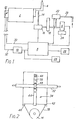
- Gas may be delivered to the oxygen sensing cell 6 by either of two routes.
- the first for burnt flue gas,-leads from the flue 4 along microbore tubing 14 (e.g. of stainless steel, copper or nylon).
- a pump 16 operating in response to a signal from the processing unit 8, draws burnt flue gas from the flue 4, along the tubing 14, through a trap 18 and thence to the cell 6.
- the trap collects and ejects any particulate matter and has an automatic drain to discharge any surplus condensate. The trap is described in greater detail. hereinafter.
- the second route is for ambient air. Air is drawn along microbore tubing 20 by a pump 22 when it is desired to check that the cell 6 is working correctly.
- a non-return valve (not shown) having a spring loaded ball is incorporated in the tubing 20.
- a transformer and heater unit 24 is fitted into the base of a chamber around the cell 6 to raise the temperature of the gas in the chmber by at least 7 0 C , to reduce or prevent condensation.
- Connection are made between the processing unit 8 and the pumps 16 and 22 and the cell 6, respectively.
- the processing unit 8 includes a read-only memory (ROM) and a random-access memory (RAM).
- the ROM permanently stores the operating program corresponding to the flow chart of Fig. 3, the value of the proportion of free oxygen gas in ambient air, and information relating the proportion of unburnt oxygen in the burnt flue gas to fuel supply rate when the boiler is operating efficiently, for the full range of possible fuel supply rates to the boiler. The latter information is burnt into the ROM following tests on the boiler in situ, before the control system is used.
- a numerical LED display unit 26 is connected to the processing unit 8 to display the numerical value for the proportion of oxygen in the gas being detected, or last detected, by the cell 6.
- the unit 26 can also display a fault condition.
- the unit is for mounting on the front of a cabinet (not shown) which houses most of the other parts of the control system.
- a switching unit 28 is mounted on the front of the cabinet to cause the damper 12 to open fully should the mains supply to the boiler or control system be interrupted.
- the switching unit includes a rechargable NiCad battery kept under constant charge. The battery causes the damper to open fully whenever the mains supply is interrupted either by intention, for example on turning off the mains switch on the front of the cabinet or as a result of failure, for example of the mains electricity supply.
- Fig. 1 two lines are shown between the boiler 2 and the processing unit 8.
- One line 30 is a cable connected at the boiler end to a moving part of a fuel valve and at the microprocessor end to a potentometer (not shown) and analogue to digital converter, whereby a digital signal indicative of the fuel supply rate is delivered to the microprocessor.
- the other line 32 is a cable connected between the damper 12 and the motor unit 10. The motor unit 10 operates in response to a signal either from the processing unit 8 or from the switching unit 28.
- the cables 30 and 32 may be Bowden or Teleflex-Morse cables. Other flexible cables for transmitting movement could also be used, as could more rigid mechanical linkages.
- the movement of the fuel valve effects movement of the air damper directly in a relatively basic manner and the function of the control system is to superimpose on this basic movement of the air damper trimming movements to bring the boiler to more efficient operation.
- Movement of the fuel valve directly causes movement of the damper through the agency of a cable 30.
- the arrangement shown in Fig. 2 is for superimposing onto the basic movement described above the calculated trimming movement to cause the damper to adopt the correct position for more efficient boiler operation.
- the cable 32 which has relatively movable inner and outer parts, and which is caused to move in a relatively uncontrolled manner when the fuel valve moves, is gripped by an actuator 34 of the motor unit 10.
- the unit 10 - uses a motor, the armature 36 of which is shown.
- the armature drives a belt 38 which passes over a pair of small rollers 40 and 42. Between the rollers the belt is connected to a lever 44 pivoted at its end 46 remote from the belt and clamped at an intermediate position to the outer sheath of the cable 32, by means of a cable grip 48.
- the cable grip is screwed to the lever on either side of the cable 32.
- the lever is drilled with a row of holes 50 and an adjacent pair are chosen having regard to whether the damper to be controlled requires to be moved a larger or a smaller amount as a result of a given movement of the motor.
- This arrangment faithfully transmits calculated trimming movements from the stepping motor to the damper.
- trimming movement is superimposed on the basic movement of the cable by a linear ram.
- the ram is moved back and forth by a motor in a direction generally along the cable.
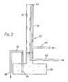
- the trap 18 shown in Fig. 3 has a chamber 52 formed by a sump portion 54 at the bottom and a columnar condenser portion 56 rising from the sump portion.
- Three ducts communicate with the interior of the chamber 52 and the chamber is otherwise enclosed.
- the three ducts are: a siphonic duct 58 serving as an outlet for condensed liquid from the sump portion 54; and a gas inlet duct 60 and a gas outlet duct 62 both communicating with the condenser portion.
- the inlet duct causes burnt flue gas to enter the condenser portion adjacent the lower end thereof.
- the outlet duct enters the chamber 52 at a low position and extends along the condenser portion to terminate adjacent the top of the condenser portion to communicate with said condenser portion via the open upper end 64 of the outlet duct.
- the cross section of the inlet and outlet ducts is considerably smaller than the cross section of the condenser portion, along which gas must flow therebetween.
- the siphonic duct 58 is a generally U-shaped tube and has one end 66 within the sump portion 54 just above the lowest part thereof and the other end 68 outside the sump portion, just below the height of the lowest part of the sump portion.
- the high point of the siphonic duct is lower than the position at which the gas inlet duct 60 communicates with the chamber. Thus, gas entering the chamber never has to bubble through collected condensate.
- burnt flue gas enters the condenser portion of the chamber at a low position thereof. Having just left the relatively narrow inlet duct 60 and entered the wider condenser tube it flows upwards slowly, towards the outlet duct 62. As it does so it passes over the inner surface of the wall of the condenser portion and the outer surface of the outlet duct. Water vapour and any oil mist in the burnt flue gas condenses on these surfaces, and in doing so may also tend to remove particulate matter from the gas stream. When the burnt flue-gas reaches the top of the condenser portion it enters the narrow outlet duct and passes on to the oxygen sensing cell.
- the liquid condensing within the condenser portion accumulates into droplets 70 which trickle down into the sump portion 54.
- the level of condensate in the sump portion reaches the level of the top of the narrow siphonic duct 58 (as it is about to do in Fig.3) the condensate is siphoned out of the sump portion. Due to the position of the ends of the siphonic duct the sump portion will virtually empty and heavy particulate matter in the condensate will be discharged. The level of condensate in the sump portion will then rise again until it has reached the level at which the siphonic duct operates.
- the duct 58 is sufficiently narrow, having regard to the rate at which condensate runs into the sump portion, to operate as a siphon rather than a simple overflow.
- the trap 18 is constructed from copper piping.
- the column 56 is 15mm o.d. piping and the various ducts 60, 62 and 58 are 6mm o.d. piping.
- the lower part of the chamber 52, which part largely forms the sump portion, is a Tee piece of 22mm o.d. The ends of the Tee piece, and the top of the column 56, are sealed by end caps.
- the total height of the trap in this embodiment is 500mm and the high point of the siphon is 120mm from the empty level of the sump portion.
- a trap In tests running against a back pressure of 6mm water gauge such a trap has been found to be well suited to gas sampling where up to 3 litres/minute of gas were being pumped through into a electro-chemical cell for analysis. Larger or small units can of course be constructed for different applications.
- the temperature of the condenser portion should be kept below the dew-point of the gas. Depending on the circumstances, it may be necessary to provide cooling means whereby this is arranged.
- the inlet duct 60 could enter the chamber at a lower position to that described above, such that the gas would have to bubble through condensate and up into the condensor portion.
- control system may be summarised as follows.
- the boiler or furnace starts up the control system immediately begins to operate. Its first main function is to open the damper fully. It then checks the correct functioning of the oxygen sensing cell 6 by operating pump 22 to draw in ambient air. The sensed proportion of oxygen in the air is compared with a stored value of 20.9%. If the cell is functioning correctly the system tests for the proportion of unburnt oxygen in the flue gas. Thus, pump 22 is stopped and pump 16 started. Burnt flue gas is drawn from the flue stack and passes through the trap 18 to the cell 6, where it is heated, to prevent water vapour condensing in the cell, by heater 24.
- the oxygen percentage level is ascertained and compared with a reference level which has been selected from the stored values as a result of a signal delivered to the processing unit 8 indicating the fuel valve position. If the comparison reveals that the oxygen level is too high or too low the microprocessor calculates the adjustment to be made in the position of the damper, which is'duly adjusted. The microprocessor now waits for the damper adjustment to take effect (waiting typically 20 to 45 seconds) and the sequence is repeated, until the unburnt oxygen level in the flue gas is within a predetermined range about the reference level. We have found that the number of sequences needed for the unburnt oxygen level to be within the preset range will not normally exceed four.
- the microprocessor After a sample portion has been drawn which indicates that the unburnt oxygen level is within the preset range (or, if preferred, after two successive sample portions have been drawn with both indicating that the oxygen level is within the range), the microprocessor goes into a 'snooze' mode and will take no further action until either the fuel supply rate changes, or until a predetermined interval has elapsed. The latter could for example be 2 hours.
- the microprocessor thus runs a self-check sequence at predetermined intervals during unchanging operation of the boiler. This involves checking the cell operation by drawing in ambient air.
- the control system is shut down and the display unit 26 displays the legend 'FAULT CONDITION'.
- the display unit is also used to automatically display the last percentage value of oxygen detected, either in the sample portion of the burnt flue gas or in ambient air.
- the user may operate a switch to display on the control unit the reference level, or set point, of unburnt oxygen for the fuel supply rate.
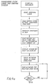
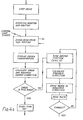
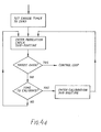
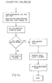
- Figs. 4 set out in detail the steps by which the operations described above executed.
- the operations shown include reading from the ROM information relating to the optimum proportion of unburnt oxygen in the flue gas for various supply rates (or a proportionality constant therebetween should the relationship be linear) and the various times at which different operations should be executed. This information is stored in the RAM. An initial oxygen set point is set in accordance with the fuel supply rate and the motor unit then moves the damper to its fully open position. The programme then enters a calibration subroutine (indicated in Fig. 4b and set out more fully as Fig.
- a control loop which involves: pumping burnt flue gas to the cell 6 and, after a predetermined interval, determining the proportion of oxygen therein (see the read stack sub-routine of Fig. 4f); periodically checking whether or not the fuel supply rate has changed by reading the fuel valve position and comparing it with the previous position (see the modulation check sub-routine of Fig.
- the program then exists from the control loop and enters a snooze loop.
- the snooze loop is left when the fuel valve position changes, the control loop being re-entered if the position has been changed.
- the control loop is moreover re-entered after a predetermined interval of unchanging boiler or furnace operation. At set intervals during the snooze period the calibration loop is re-entered to check the cell operation.
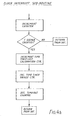
- the clock interrupt sub-routine on Fig. 4h shows how a clock timer interrupting the microprocessor is used to control the incrementing of the calibration and snooze counters and the decrementing of time out counters.
Landscapes
- Engineering & Computer Science (AREA)
- Chemical & Material Sciences (AREA)
- Combustion & Propulsion (AREA)
- Mechanical Engineering (AREA)
- General Engineering & Computer Science (AREA)
- Regulation And Control Of Combustion (AREA)
Applications Claiming Priority (2)
| Application Number | Priority Date | Filing Date | Title |
|---|---|---|---|
| GB8308902 | 1983-03-31 | ||
| GB8308902 | 1983-03-31 |
Publications (2)
| Publication Number | Publication Date |
|---|---|
| EP0121437A2 true EP0121437A2 (fr) | 1984-10-10 |
| EP0121437A3 EP0121437A3 (fr) | 1985-01-23 |
Family
ID=10540531
Family Applications (1)
| Application Number | Title | Priority Date | Filing Date |
|---|---|---|---|
| EP84302239A Withdrawn EP0121437A3 (fr) | 1983-03-31 | 1984-04-02 | Système de contrôle pour une chaudière ou un four |
Country Status (1)
| Country | Link |
|---|---|
| EP (1) | EP0121437A3 (fr) |
Cited By (4)
| Publication number | Priority date | Publication date | Assignee | Title |
|---|---|---|---|---|
| AU690053B2 (en) * | 1996-05-22 | 1998-04-09 | Toyota Jidosha Kabushiki Kaisha | Method and apparatus for controlling combustion using an oxygen sensor |
| EP1113224A3 (fr) * | 1999-12-31 | 2003-09-17 | Robert Bosch Gmbh | Brûleur à gaz |
| US8568632B2 (en) | 2003-11-26 | 2013-10-29 | Owens Corning Intellectual Capital, Llc | Method of forming thermoplastic foams using nano-particles to control cell morphology |
| DE102008016047B4 (de) | 2007-04-02 | 2019-01-24 | Vaillant Gmbh | Verfahren zur Füllstandsüberwachung |
Family Cites Families (7)
| Publication number | Priority date | Publication date | Assignee | Title |
|---|---|---|---|---|
| US3404836A (en) * | 1965-12-20 | 1968-10-08 | Westinghouse Electric Corp | Heat generating apparatus |
| US3602487A (en) * | 1969-11-10 | 1971-08-31 | Jones & Laughlin Steel Corp | Blast furnace stove control |
| US4238185A (en) * | 1977-05-25 | 1980-12-09 | Telegan Limited | Control system for a burner |
| US4160170A (en) * | 1978-06-15 | 1979-07-03 | United Technologies Corporation | Wind turbine generator pitch control system |
| DE3039994A1 (de) * | 1980-10-23 | 1982-05-06 | Karl Dungs Gmbh & Co, 7067 Urbach | Verfahren zur einstellung von verbundreglern fuer brenner in waermeerzeugungsanlagen |
| US4360336A (en) * | 1980-11-03 | 1982-11-23 | Econics Corporation | Combustion control system |
| DE3103940A1 (de) * | 1981-02-05 | 1982-08-12 | Günter Dr.-Ing. 7405 Dettenhausen Baumbach | Vorrichtung zur ueberwachung von feuerungsabgasen |
-
1984
- 1984-04-02 EP EP84302239A patent/EP0121437A3/fr not_active Withdrawn
Cited By (5)
| Publication number | Priority date | Publication date | Assignee | Title |
|---|---|---|---|---|
| AU690053B2 (en) * | 1996-05-22 | 1998-04-09 | Toyota Jidosha Kabushiki Kaisha | Method and apparatus for controlling combustion using an oxygen sensor |
| US5938423A (en) * | 1996-05-22 | 1999-08-17 | Toyota Jidosha Kabushiki Kaisha | Method and apparatus for controlling combustion using an oxygen sensor |
| EP1113224A3 (fr) * | 1999-12-31 | 2003-09-17 | Robert Bosch Gmbh | Brûleur à gaz |
| US8568632B2 (en) | 2003-11-26 | 2013-10-29 | Owens Corning Intellectual Capital, Llc | Method of forming thermoplastic foams using nano-particles to control cell morphology |
| DE102008016047B4 (de) | 2007-04-02 | 2019-01-24 | Vaillant Gmbh | Verfahren zur Füllstandsüberwachung |
Also Published As
| Publication number | Publication date |
|---|---|
| EP0121437A3 (fr) | 1985-01-23 |
Similar Documents
| Publication | Publication Date | Title |
|---|---|---|
| CN106092246B (zh) | 用于确定不凝气体的量的装置和方法 | |
| US5988232A (en) | Vapor recovery system employing oxygen detection | |
| FI62596C (fi) | Foerfarande och anordning foer rensning av gasroer och gasfilter | |
| US6276894B1 (en) | Method and device for drawing condensate off from compressed-gas systems | |
| KR20100113495A (ko) | 기체 혼합물 조성 검출 방법 및 장치 | |
| EP0121437A2 (fr) | Système de contrôle pour une chaudière ou un four | |
| US4382173A (en) | System for automatically regulating water conductivity in an electrode-type humidifier evaporator | |
| KR20010007413A (ko) | 연소기기 | |
| ATE110159T1 (de) | Vorrichtung zum ableiten von kondensat für gasbeheizte brennwertkessel. | |
| DK0811345T3 (da) | Apparat til levering af varmt vand | |
| US4398663A (en) | Heating system with steam radiators | |
| NZ533839A (en) | Percolation test apparatus | |
| KR100361151B1 (ko) | 콘덴싱 보일러의 응축수받이 수위제어장치 및 그 방법 | |
| JP2925497B2 (ja) | ボイラの間欠ブロー制御方法 | |
| JPH1019865A (ja) | 呼気分析装置 | |
| EP1677108A2 (fr) | Appareil de mesure du mercure contenu dans un environnement gazeux | |
| AU642445B2 (en) | Heater for liquid | |
| JP3611022B2 (ja) | 汚泥の強熱減量計測方法 | |
| JP3969900B2 (ja) | 汚泥試料の供給方法および汚泥試料供給装置 | |
| JP3063514B2 (ja) | 圧力センサによる流量測定方法 | |
| JP3140709B2 (ja) | 湿球ウイック給水装置 | |
| JP3276575B2 (ja) | 硬水軟化装置の硬度漏れ検出装置 | |
| JPH0552506U (ja) | ボイラの自動ブロー装置 | |
| JP3077789B2 (ja) | ボイラの演算濃縮ブロー制御方法 | |
| JPH07167864A (ja) | 血液アルコール値の検出方法および検出装置 |
Legal Events
| Date | Code | Title | Description |
|---|---|---|---|
| PUAI | Public reference made under article 153(3) epc to a published international application that has entered the european phase |
Free format text: ORIGINAL CODE: 0009012 |
|
| AK | Designated contracting states |
Designated state(s): AT BE CH DE FR GB IT LI LU NL SE |
|
| PUAL | Search report despatched |
Free format text: ORIGINAL CODE: 0009013 |
|
| AK | Designated contracting states |
Designated state(s): AT BE CH DE FR GB IT LI LU NL SE |
|
| 17P | Request for examination filed |
Effective date: 19850723 |
|
| 17Q | First examination report despatched |
Effective date: 19870409 |
|
| STAA | Information on the status of an ep patent application or granted ep patent |
Free format text: STATUS: THE APPLICATION IS DEEMED TO BE WITHDRAWN |
|
| 18D | Application deemed to be withdrawn |
Effective date: 19870811 |
|
| RIN1 | Information on inventor provided before grant (corrected) |
Inventor name: KELSALL-SPURR, JOHN KENNETH FRANCIS |