EP0121475B1 - Verfahren und Vorrichtung zur chirurgischen Abschliessung und zum Schneiden - Google Patents
Verfahren und Vorrichtung zur chirurgischen Abschliessung und zum Schneiden Download PDFInfo
- Publication number
- EP0121475B1 EP0121475B1 EP84400636A EP84400636A EP0121475B1 EP 0121475 B1 EP0121475 B1 EP 0121475B1 EP 84400636 A EP84400636 A EP 84400636A EP 84400636 A EP84400636 A EP 84400636A EP 0121475 B1 EP0121475 B1 EP 0121475B1
- Authority
- EP
- European Patent Office
- Prior art keywords
- clip
- clips
- jaws
- tissue
- assembly
- Prior art date
- Legal status (The legal status is an assumption and is not a legal conclusion. Google has not performed a legal analysis and makes no representation as to the accuracy of the status listed.)
- Expired
Links
- 238000005520 cutting process Methods 0.000 title claims description 10
- 238000000034 method Methods 0.000 title description 3
- 230000007246 mechanism Effects 0.000 claims description 26
- 239000000463 material Substances 0.000 claims description 19
- 230000000712 assembly Effects 0.000 claims description 4
- 238000000429 assembly Methods 0.000 claims description 4
- 238000012163 sequencing technique Methods 0.000 claims 2
- 230000000452 restraining effect Effects 0.000 description 42
- 238000003860 storage Methods 0.000 description 18
- 239000002184 metal Substances 0.000 description 15
- 238000001356 surgical procedure Methods 0.000 description 6
- 229920003023 plastic Polymers 0.000 description 4
- 210000004204 blood vessel Anatomy 0.000 description 3
- 230000006835 compression Effects 0.000 description 3
- 238000007906 compression Methods 0.000 description 3
- 239000004033 plastic Substances 0.000 description 3
- 238000010618 wire wrap Methods 0.000 description 3
- 230000000903 blocking effect Effects 0.000 description 2
- 238000002788 crimping Methods 0.000 description 2
- 230000004048 modification Effects 0.000 description 2
- 238000012986 modification Methods 0.000 description 2
- 229920000728 polyester Polymers 0.000 description 2
- RKDVKSZUMVYZHH-UHFFFAOYSA-N 1,4-dioxane-2,5-dione Chemical compound O=C1COC(=O)CO1 RKDVKSZUMVYZHH-UHFFFAOYSA-N 0.000 description 1
- 229920004142 LEXAN™ Polymers 0.000 description 1
- 239000004418 Lexan Substances 0.000 description 1
- 238000004026 adhesive bonding Methods 0.000 description 1
- 210000001367 artery Anatomy 0.000 description 1
- 238000005452 bending Methods 0.000 description 1
- 230000008901 benefit Effects 0.000 description 1
- 230000002146 bilateral effect Effects 0.000 description 1
- 239000008280 blood Substances 0.000 description 1
- 210000004369 blood Anatomy 0.000 description 1
- 230000000295 complement effect Effects 0.000 description 1
- 238000010276 construction Methods 0.000 description 1
- 229920001577 copolymer Polymers 0.000 description 1
- 230000006378 damage Effects 0.000 description 1
- 230000000694 effects Effects 0.000 description 1
- 239000012530 fluid Substances 0.000 description 1
- 239000003292 glue Substances 0.000 description 1
- 230000023597 hemostasis Effects 0.000 description 1
- JJTUDXZGHPGLLC-UHFFFAOYSA-N lactide Chemical class CC1OC(=O)C(C)OC1=O JJTUDXZGHPGLLC-UHFFFAOYSA-N 0.000 description 1
- 230000007257 malfunction Effects 0.000 description 1
- 238000004519 manufacturing process Methods 0.000 description 1
- 238000002406 microsurgery Methods 0.000 description 1
- 210000003101 oviduct Anatomy 0.000 description 1
- 229920002647 polyamide Polymers 0.000 description 1
- 229920000515 polycarbonate Polymers 0.000 description 1
- 239000004417 polycarbonate Substances 0.000 description 1
- 229920000642 polymer Polymers 0.000 description 1
- 230000004044 response Effects 0.000 description 1
- 230000000979 retarding effect Effects 0.000 description 1
- 238000000926 separation method Methods 0.000 description 1
- 238000003892 spreading Methods 0.000 description 1
- 230000007480 spreading Effects 0.000 description 1
- 239000000126 substance Substances 0.000 description 1
- 230000000451 tissue damage Effects 0.000 description 1
- 231100000827 tissue damage Toxicity 0.000 description 1
- 210000003954 umbilical cord Anatomy 0.000 description 1
- 210000001177 vas deferen Anatomy 0.000 description 1
- 210000003462 vein Anatomy 0.000 description 1
- 238000003466 welding Methods 0.000 description 1
Images








Classifications
-
- A—HUMAN NECESSITIES
- A61—MEDICAL OR VETERINARY SCIENCE; HYGIENE
- A61B—DIAGNOSIS; SURGERY; IDENTIFICATION
- A61B17/00—Surgical instruments, devices or methods
- A61B17/12—Surgical instruments, devices or methods for ligaturing or otherwise compressing tubular parts of the body, e.g. blood vessels or umbilical cord
- A61B17/128—Surgical instruments, devices or methods for ligaturing or otherwise compressing tubular parts of the body, e.g. blood vessels or umbilical cord for applying or removing clamps or clips
Definitions
- This invention relates to surgical apparatus, and more particularly to surgical apparatus used to occlude or ligate and to divide body tissue, and comprising means for simultaneously applying two clips of plastic-like material around the tissue structure at two spaced apart locations along the tissue structure to ligate the tissue structure at the locations of the clips.
- An apparatus of this type is disclosed in US-A-3 175 566.
- Ligating and dividing surgical instruments have typically used metal staples, fasteners, or ligatures to ligate organic tissue structures such as blood vessels.
- One such system is disclosed in US-A-3 955 581.
- the apparatus described in that patent operates in three stages to positively control the operations of its metal staple-carrying cartridge.
- the main body of the cartridge is moved forward toward an anvil assembly fixed on the instrument, thereby enclosing the tissue structure within the jaws of the cartridge.
- a pair of metal staples is then pushed forward to encircle the tissue structure at spaced apart locations.
- the staples are crimped or clinched against the fixed anvil assembly to ligate the tissue at the locations of the staples.
- a knife blade advances to the fixed anvil assembly and divides the tissue structure intermediate the two staples.
- US-A-4 086 926 Another metal staple-carrying cartridge is described in US-A-4 086 926, which operates in three stages. Two laterally spaced metal staples are formed around a tissue structure by means of a fixed anvil assembly, thus ligating the tissue structure. A knife then advances to the fixed anvil assembly and divides the ligated structure between the staples.
- the staple feeding arrangement in that apparatus comprises a pair of belts, each carrying a plurality of staples.
- ligatures in the form of fasteners of clips of X-ray-transparent plastic or plastic-like materials may be preferable to X-ray-opaque metal staples.
- plastic or plastic-like materials will be referred to generically as plastic-like materials.
- clips of plastic-like material also have the advantage that they can be made biologically absorbable.
- plastic-like clips cannot be simply substituted for metal staples in prior ligating and dividing instruments because plastic-like clips cannot be closed by clinching or crimping in the way that metal staples are clinched or crimped. Unlike metal staples, plastic-like clips will not hold a shape to which they are deformed unless parts of the clip mechanically interlock with one another. Thus the means employed in prior ligating and dividing instruments for clinching or crimping metal staples around the tissue are not suitable for use with plastic-like clips. The problems of storing and feeding plastic-like clips are also different from those associated with metal staples.
- a surgical apparatus for ligating and dividing organic tissue structures of the above type, characterized in that the means for applying two clips around the tissue structure to ligate said tissue structure atthe locations of the clips include first and second substantially parallel laterally spaced clip applying assemblies, each assembly containing a respective one of said clips, and each assembly including a pair of jaws fixed relative to one another forming a discharge opening and disposed on respective opposite sides of the tissue structure and means for forcing the associated clip completely through the jaws of the assembly so that the clip closes to the fixed relationship of the jaws as it is forced through said discharge opening, and in that the apparatus further comprises means for cutting the tissue structure between the clips, according to the characterizing portion of claim 1.
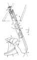
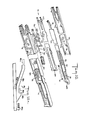
- a surgical instrument for ligating and dividing in accordance with the present invention is shown generally at reference numeral 10.
- a hand 12 is shown gripping a handle 14 to which is attached a hollow trigger 16.
- Trigger 16 is shown in the open position, before a ligating and dividing surgical procedure is performed.
- Handle 14 forms part of the body of instrument 10, which also includes an actuating assembly.
- a clip storage assembly is shown generally at reference numeral 18, and is attached to handle 14 by the actuating mechanism.
- Two tracks 20 and 22 run parallel to the longitudinal axis of instrument 10. The longitudinal axis is shown by broken line 8 in FIGURE 1.
- the tracks have transverse channels 24 formed therein at spaced apart locations for receiving tabs on the metallic housing or wrap 94 of clip storage assembly 18 in order to secure the wrap to the channels.
- a tissue gathering or tissue restraining assembly 26 is shown in its initial open position for receiving a tubular vessel 28, such as a blood vessel, duct, or other organic structure.
- a tubular vessel such as a blood vessel, duct, or other organic structure.
- tubular vessel as used herein is intended to connote an artery, a vein, an umbilical cord, a capillary, or any flexible and/or deformable tissue structure which is capable of being clamped and then severed.
- Trigger assembly 30 consists of hollow trigger 16 and trigger insert 32.
- Trigger insert 32 has an upper bar portion 33 and a lower portion, not shown in this FIGURE, extending in and along substantially the entire length of hollow trigger 16. The lower portion of trigger insert 32 is fastened to hollow trigger 16 by rivets, glue, or other conventional means.
- the body of instrument 10, which includes handle 14 and trigger 16, is manufactured from a plastic material such as ABS supplied by the Borg-Warner Company.
- Clip storage assembly 18 and tissue restraining assembly 26 are manufactured from a polycarbonate or similar material such as LEXAN polymer manufactured by the General Electric Company.
- Trigger assembly 30 has a pivot pin 34 by which the trigger assembly is mounted to handle 14.
- Handle 14 consists of two halves 14a and 14b which are substantially identical mirror images of each other. Accordingly, instrument 10 is substantially symmetrical about a vertical plane that passes through longitudinal axis 8. There are some exceptions to the general bilateral symmetry of instrument 10. These exceptions will become apparent as the description proceeds.
- Handle halves 14a and 14b are joined together by sonic welding or any other suitable means, such as by gluing or rivetting.
- the right half 14a of the handle has molded ribs 15a and 15b which are tissue restraining assembly bar stops.
- Both halves of handle 14 also have molded ribs 15c which are clip storage assembly stops (see also FIGURE 15).
- the right half 14a of the handle has a pin 36 which protrudes perpendicular to both the longitudinal vertical axis of handle 14 and the longitudinal axis 8 of instrument 10.
- Attached to pin 36 is one end of tissue restraining assembly return spring 38, which is a prestressed tension coil spring.
- the other end of spring 38 is connected to tissue restraining assembly spring retainer slot 40, shown in phantom. Slot 40 is formed in L-shaped tissue restraining assembly bar protrusion 45.
- one end of knife return spring 42 is connected to pin 36.
- Spring 42 is another prestressed tension coil spring. The other end of spring 42 is connected to knife spring retainer slot 43.
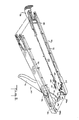
- trigger assembly 30 and its relation to tracks 20 and 22 of instrument 10 are shown.
- the upper bar portion 33 of trigger insert 32 has a curved cam surface 44.
- the upper bar portion 33 also includes a pusher pin 46, attached by conventional means, which rides in slots 48a and 48b of a left pusher bar 50 and a right pusher bar 52, respectively.
- Pusher bars 50 and 52 are relatively thin metal beams disposed in, and housed by, left and right tracks 20 and 22.
- Slots 48a and 48b are elliptical cut-outs at the proximal end of pusher bars 50 and 52 and are both oriented so that the upper portion of each slot is more proximal than the lower portion.
- a knife bar is shown at reference numeral 54 in the preferred embodiment. It will be appreciated, however, that a vessel may be divided in a number of ways besides knife or razor blade cutting, such as by laser or chemical destruction of tissue or by tearing. All such mechanisms for dividing are to be considered within the scope of the present invention.
- a flange 56 is formed on knife bar 54 at the proximal end thereof. Knife bar 54 has a scalpel or knife blade 58 vertically attached to its distal end. Flange 56 is adapted to engage the curved cam surface 44 of upper bar portion 33 upon actuation of trigger assembly 30. Actuation of trigger assembly 30 occurs when a hand squeezes hollow trigger 16 toward handle 14, advancing upper bar portion 33 in a distal direction. Flange 56 is oriented generally opposite the right pusher bar slot 48b orientation. That is, the upper portion of flange 56 is more distal than the lower portion.
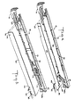
- Clip storage assembly 18 includes (1) left track 20, housing left pusher bar 50, and (2) right track 22, housing right pusher bar 52. Also contained in clip storage assembly 18 is knife bar 54 with knife blade 58. Tissue restraining assembly 26 is also part of clip storage assembly 18. Only right track 22 is described in detail below. It should be understood that the structure and operation of left track 20 is similar to that of right track 22.
- Tissue restraining assembly bar 60 is a metal beam positioned parallel to and between right pusher bar 52 and knife bar 54.
- Tissue restraining assembly bar 60 has a flange 62 for engaging pusher pin 46 (FIGURE 3) of trigger assembly 30.
- Flange 62 is oriented at a similar angle to the right pusher bar slot 48b. That is, the upper portion of flange 62 is more proximal than the lower portion.
- tissue restraining assembly bar 60 is connected to tissue restraining assembly 26 for movement therewith by means of a vertical upward protrusion 63 in tissue restraining assembly 26 which engages a slot 64 in tissue restraining assembly bar 60.
- a right pusher bar return spring 70 which is a prestressed compression coil spring, is compressed between right pusher bar 52 and stop surface 72 on right track 22.
- tissue restraining assembly 26 has a lower tissue restraining assembly surface 74 which is adapted to slide along rails 76 of right track 22 and left track 20, not shown in this FIGURE.
- Right pusher bar 52 has a spring retainer 78, parallel to the longitudinal axis of clip storage assembly 18, for positioning the proximal end of right pusher bar return spring 70.
- Temporarily positioning the distal end of right pusher bar return spring 70 prior to assembly of the apparatus is another spring retainer 80, also parallel to the longitudinal axis of clip storage assembly 18, which is part of right pusher bar 52.
- the distal end of spring 70 bears on stop surface 72, which is part of right track 22.
- the anti-jamming mechanism On the distal side of stop surface 72 is an anti-jamming mechanism 81.
- the anti-jamming mechanism which is described in greater detail below with references to FIGURES 10 and 10a, includes (1) a flag 82, which is part of right pusher bar 52, and (2) a ramp assembly 84 connected to right track 22.
- a clip spring holder also described in greater detail below with reference to FIGURE 8, is shown at reference numeral 85.
- surgical ligatures or clips 86 of plastic-like material are individually dispensable but shown interlocking in a clip stack or train.
- Clips 86 in the preferred embodiment are made from a biologically absorbable copolymer which is a polyester derivative of lactide and glycolide. Such material is absorbable by the body and is radiotranspa- rent.
- plastic-like material which can be formed into suitable clips, regardless of whether it is absorbable by the body, can be used.
- Such material may be, for example, polyester, polyamid, and the like. All such materials are generically referred to herein as plastic-like materials.
- Clips 86 releasably interlock with each other as described hereinbelow with regard to FIGURE 21 and also in US-A-4 512 345.
- Clips 86 are adapted to be pushed sequentially by the end of a clip pusher 92, which is the distal- most end of right pusher bar 52 and which pushes on the base of the distal-most clip in the train.
- the proximal-most one of clips 86 is seated in a U-shaped clip guide 88.
- Clip guide 88 prevents the last one or two clips in the train from becoming skewed in the apparatus after all of the preceding clips have been used.
- a compression coil spring 90 is prestressed between clip guide 88 and clip spring holder 85 (FIGURES 7 and 10) to give the clip train an initial boost in the distal direction. After two or three clips have been used, spring 90 serves no further purpose.
- FIGURE 9 there is illustrated a bottom view of instrument 10, showing the assembled left and right tracks 20 and 22, and a relatively thin metal housing or wire wrap 94 enclosing them.
- the two sides of wire wrap 94 are attached to one another by interlocking protrusions 96 and slots 98.
- a safety mechanism 100 is shown in phantom in this FIGURE, and is described in more detail below.
- Tissue restraining assembly 26 has a cutting post or tube 102 against which knife blade 58 (FIGURE 3) is forced during a dividing operation.
- Cutting post 102 is preferably a hollow cylindrical section manufactured from PVC material.
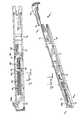
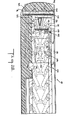
- FIGURE 10 there is shown the assembly of right track 22, including the right side of wire wrap 94, right pusher bar 52 with right pusher bar return spring 70, a cover 106 for isolating the operation of right pusher bar 52 from the clip train, the stack of interlocking clips 86, clip guide 88, guide spring 90 which fits over a post 108 on clip guide 88, clip spring holder 85, and an interior wall 91 of right track 22, including ramp 84 and a clip positioning pawl 110 toward the distal-most end of interior wall 91.
- the operation of pawl 110 is described in detail below with reference to FIGURES 24 et seq.
- Cover 106 has a pair of detents or resistance dimples 107 formed therein for helping to uncouple the distal-most clip from the clip train as described in detail below.
- Actuation assembly 112 includes trigger assembly 30, knife bar 54, right pusher bar 52, left pusher bar 50 and the associated pusher bar return spring (not shown in this FIGURE), pusher pin 46, knife return spring 42, and right pusher bar return spring 70.
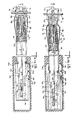
- FIGURE 12 there are shown the two tracks 20 and 22. Between tracks 20 and 22 are vertical knife blade 58 and tissue restraining assembly bar 60. The end portions of right and left clips 86 are also shown in this drawing, disposed in left and right channels 114 and 116, respectively. Channels 114 and 116 are formed by covers 106, which isolate operation of pusher bars 50 and 52 (FIGURE 3), and interior walls 91. A train of clips 86 is contained within each of channels 114 and 116.
- FIGURE 14 is a view of the distal-most end of instrument 10 taken along the line 14-14 in FIGURE 13.
- FIGURES 15-30 In order to describe the operation of instrument 10 in stages during a complete surgical procedure, reference should also now be made to remaining FIGURES 15-30.
- FIGURE 11 illustrates the position of each of the elements before a ligating and dividing cycle is initiated.
- tissue such as tubular vessel 28 is placed in tissue restraining assembly 26 of instrument 10.
- Knife bar 54 and blade 58, as well as left and right pusher bars 50 and 52 and left and right tracks 20 and 22 are all in their proximal-most or retracted positions.
- Tissue restraining assembly 26 is also in its proximal-most position.
- trigger 16 (FIGURE 11) is in its open position.
- trigger assembly 30 is rotated counter-clockwise about pivot 34.
- Such rotation forces both ends of pusher pin 46 on trigger insert 32 to move in their respective slots 48a and 48b in left and right pusher bars 50 and 52, respectively.
- pusher bars 50 and 52 are forced to begin to move distally.
- the prestress compression force exerted by right pusher bar return spring 70 (FIGURE 5) and left pusher bar return spring (not shown) is less than the prestress tension force exerted by knife return spring 42.
- left and right tracks 20 and 22 move with pusher bars 50 and 52, and the entire housing advances distally relative to tissue restraining assembly 26 to close around and grip tissue 28 between tissue restraining assembly 26 and the rest of clip storage assembly 18.
- Knife bar 54 and knife blade 58 move distally with tracks 20 and 22 because upward projection 55 (FIGURE 4) on knife bar 54 bears against the proximal end of slot 21 (FIGURE 2) which is formed between tracks 20 and 22.
- Knife return spring 42 is extended during distal movement of tracks 20 and 22 as described above, but tissue restraining return spring 38 does not extend during this phase of the operating cycle of the apparatus.
- Knife bar 54 advances at a greater rate of speed than pusher bars 50 and 52. Knife return spring 42 extends accordingly.
- tissue restraining bar 60 (FIGURE 4). This initiates distal motion of bar 60 and tissue restraining assembly 26 so that by the stage shown in FIGURE 18, L-shaped tissue restraining assembly bar protrusion 45 has moved a distance "d” from stop 15a, and tissue restraining assembly 26 has moved a similar distance "d” relative to tracks 20 and 22.
- Tissue restraining assembly return spring 38 (FIGURE 2) is extended by distal motion of tissue restraining assembly bar 60.
- Clips 86 are then formed, as described in greater detail below, to close around tissue 28, ligating it at two spaced apart locations. Tissue restraining assembly bar60 and tissue restraining assembly 26 move distally during this phase of the procedure so that closed clips 86 can be fully ejected from the clip forming jaws described in detail below without causing the tissue to stretch prior to cutting.
- tissue restraining assembly 26 As trigger 16 is squeezed still farther toward handle 14, knife blade 58 cuts tissue 28 against tube 102, as shown in FIGURE 19.
- knife bar 54 and blade 58 force tube 102 of tissue restraining assembly 26 to move distally, separating tissue restraining assembly bar 60 from pin 46.
- pin 46 no longer engages tissue restraining assembly bar 60, but tissue restraining assembly 26 nevertheless continues to be forced distally by knife bar 54 and blade 58.
- the two closed clips 86 are completely ejected from the clip forming jaws described below.
- Tissue restraining assembly bar 60 stops moving distally when L-shaped protrusion 45 contacts tissue restraining assembly bar stop 15b. This coincides with trigger 16 being fully closed.
- Tissue restraining assembly 26 does not move proximally as far as tracks 20 and 22, thereby allowing tissue 28 and its attached clips 86 to be removed from instrument 10.
- the safety mechanism 100 further described hereinbelow, is shown blocking passage of knife blade 58 when a mis-feed of a clip 86 occurs in right track 22.
- Each clip 86 includes a base 130 and two arms 132 and 134 extending from respective opposite ends of the base.
- the base 130 and arms 132 and 134 of each clip 86 lie in a common plane.
- Each clip 86 is made so that the normally free end portions 136 and 138 of arms 132 and 134 are resiliently biased apart.
- Laterally extending lugs 142 and 144 are respectively located along arms 132 and 134.
- the inner periphery of the normally free end portion 136 and 138 of each arm 132 and 134 includes a slot 146 and 148, respectively.
- each clip 86 When the physically separate and individual clips 86 are associated with one another in a train, as shown for example in FIGURE 10, the lugs 142 and 144 of each clip 86 are respectively releasably received in and engaged by the slots 146 and 148 in the immediately following clip 86.
- the arms 132 and 134 of each clip 86 are prevented from spreading farther apart by the surrounding structure of instrument 10. Accordingly, when the distal-most clip 86 in the train is pushed in the distal direction as described in detail below, all of the succeeding clips 86 in the train are pulled along at the same time.
- Resistance dimples 107 retard advancement of the rest of the clip train as the distal-most clip 86 is advanced, thus helping to uncouple the distal-most clip from the clip train.
- the normally free end portions 136 and 138 of the arms of each clip 86 also include complementary latching elements 132a and 132b on arm 132 and 134a and 134b on arm 134.
- latching elements 132a and 134a overlap and interlock with one another
- latching elements 132b and 134b similarly overlap and interlock with one another. Once these latching elements interlock, they hold clip 86 closed.
- the sense or direction of the overlap of latching elements 132a and 134a is opposite to the sense or direction of the overlap of latching elements 132b and 134b. This makes the clip 86 highly resistant to inadvertent reopening by helping to keep arms 132 and 134 coplanar.
- FIGURE 23 shows the position of two closed clips 86 after a tubular vessel 28 has been ligated at two spaced apart locations and divided intermediate the clips 86.
- Clips 86 may have various sizes depending on their intended use. Typical clips may be about 10 mm long and 8 mm wide before being closed. Much smaller clips may be used for certain applications in microsurgery. Larger clips may be used for other purposes such as closing oviducts and vas deferens. Instrument 10 is sized appropriately for the clips it is to apply.
- FIGURES 24-28 operation of the distal end of instrument 10, and more particularly clip storage assembly 18, is shown during the stages of a tissue ligating and dividing surgical procedure. Closure or forming of surgical clips 86 by means of forcing them through fixed jaws of a surgical instrument is explained in detail in US-A-4 492 232.
- FIGURE 24 The initial condition of the apparatus is shown in FIGURE 24.
- a plurality of clips 86 are coupled together in two trains as described above and disposed in left and right channels 114 and 116 (FIGURE 12) with the open side of each clip 86 facing in the distal direction toward a set of jaws 160, shown in phantom, oppositely disposed in each channel 114 and 116.
- One set of jaws 160 consisting of an upper and lower member, is disposed in each channel 114 and 116.
- the base 130 of the distal-most clip 86 in the train in channel 116 is initially on the distal side of clip pusher 92 and pawl 110.
- the bases 130 of all the other clips 86 in channel 116 are on the proximal side of clip pusher 92 and pawl 110.
- Right pusher bar 52 is in its proximal-most position, which corresponds to trigger 16 and handle 14 (FIGURE 1) being at their maximum separation (i.e., 0% of the way towards a closed position).
- the left side of the apparatus which is not described in detail herein, is constructed and operates similarly.
- Two flag stop assemblies 158 and 159 are each disposed perpendicular to knife blade 58 (FIGURE 3) and on either side thereof for a hereinafter described purpose.
- the body tissue 28 to be ligated is positioned between jaws 160 and the distal-most portion of tissue restraining assembly 26, as shown in FIGURE 24.
- right pusher bar 52 is driven in the distal direction.
- right clip pusher 92 moves distally past the distal end of clip positioning pawl 110 (compare Figures 25 and 26; see also Figures 16 and 17), contacts the proximal side of the base 130 of distal-most clip 86, and advances that clip in the distal direction along its channel 116. All of the other clips in the train are pulled along with the distal-most clip.
- An identical procedure occurs, of course, on the left side of the instrument in the left track 20.
- each arm 132 and 134 of the distal-most clip 86 enters a respective one of jaws 160 so that an arm of each clip is on each side of tissue 28.
- Each of jaws 160 has a longitudinal jaw channel 162 for receiving and guiding an arm of a clip 86. Jaw channels 162 keep their respective clips 86 in the proper orientation in the instrument until the clips 86 have been closed.
- arms 132, 134 of the distal-most clip 86 contact converging jaw surfaces 164, arms 132 and 134 begin to deflect or pivot toward one another so that the clip 86 begins to close on the tissue 28.
- lugs 142 and 144 on the distal-most clip 86 disengage from slots 146 and 148 respectively in the next-to-distal-most clip 86, thereby uncoupling the distal-most clip 86 from the remaining clips in the train.
- resistance dimples 107 engage arms 132 and 134 of the succeeding clip proximate the distal-most clip 86, retarding further distal motion of the next-to-distal-most clip.
- This uncoupling of the distal-most clip occurs after the base 130 of the next-to-distal-most clip has moved to the distal side of the distal end of pawl 110 but before the base 130 of another clip has moved to the distal side of the distal end of pawl 110. This assures that one clip, and only one clip, is advanced to jaws 160 on each side of knife blade 58 during each operating cycle of the instrument.
- distal-most clip 86 When the instrument 10 reaches the condition shown in FIGURE 27, distal-most clip 86 is fully closed and latching elements 132a and 132b (FIGURE 21) respectively interlock with latching elements 134a and 134b to hold the clip closed.
- closed clip 86 exerts sufficient pressure on tissue 28 to provide hemostasis without causing undue tissue damage.
- Anti-jamming mechanism 81 (FIGURES 7, 10, and 10a) is provided to prevent another clip 86 from being advanced in either of channels 114 and 116 until the preceding clips have been completely closed and ejected from those channels.
- flag 82 is located relative to ramp assembly 84 as shown in FIGURE 7 and at reference number 82a in FIGURE 10a.
- pusher bar 52 begins to advance relative to track 22
- flag 82 moves to position 82b in FIGURE 10a shortly after the distal end of clip pusher 92 moves distally past the distal end of pawl 110.
- latch surface 83 on ramp assembly 84 prevents flag 82 from retracting in the proximal direction, even if trigger 16 is prematurely released. This prevents clip pusher 92 from retracting to a position proximal of the distal end of pawl 110 and thereby picking up another clip until after the clip which pusher 92 has already begun to advance has been completely closed and ejected from the instrument.
- flag 82 passes around the distal end of ramp assembly 84 as shown at position 82c in FIGURE 10a.
- flag 82 traverses the opposite side of ramp assembly 84 as shown in part by the reference number 82d in FIGURE 10a and returns to its initial position 82a when the remainder of the instrument returns to its initial condition.
- anti-jamming mechanism 81 prevents double feeding of clips, which could cause the apparatus to malfunction and jam.
- safety mechanism 100 is positioned at a distal location in clip storage assembly 18.
- Safety mechanism 100 prevents tissue 28 (FIGURE 1) from being divided before it is ligated at both sides of the intended dividing point.
- tissue 28 FIG. 1
- tissue 28 In ligating and dividing surgical procedures, it is often important that a tubular vessel such as a blood vessel first be successfully ligated at two locations before it is divided intermediate those locations. If either one or both ligatures fail to function properly, hemor- rhaging, the uncontrolled flow of fluid (e.g., blood) from the vessel, will result upon division of the vessel.
- fluid e.g., blood
- Safety mechanism 100 has a substantially flat base 170 which is perpendicular to the planes defined by the left and right tracks 20 and 22 and parallel to the longitudinal axis 8 of the instrument.
- Base 170 spans both tracks 20 and 22 and knife bar 54.
- Base 170 has a manufacturing detent 172 on each side to facilitate maintaining a relatively clean surface upon bending of the safety mechanism extremities.
- Base 170 of safety mechanism 100 rests on interior walls 91.
- Safety mechanism 100 remains stationary with respect to tracks 20 and 22 and is prevented from moving distally during operation of instrument 10.
- Attached to either side of base 170 are arms 176 and 178 which extend along the longitudinal axis of clip storage assembly 18.
- Arms 176 and 178 are biased outwardly and extend into the upper portion of right and left clip channels 114 and 116, respectively. Arms 176 and 178 are in close proximity to covers 106. When surgical clips 86 are placed in channels 114 and 116, however, safety mechanism arms 176 and 178 contact upper clip arms 132 and are thereby forced inwardly toward centrally located knife bar 54 and blade 58.
- each arm 176 and 178 is bent substantially perpendicular to the longitudinal axis 8 of instrument 10.
- flags 180 and 182 respectively, which extend downwardly to block advancement of knife bar 54 and blade 58 when either of safety mechanism arms 176 or 178 is in close proximity to cover 106.
- Flags 180 and 182 overlap and therefore do not interfere with the operation of one another. This is due to the fact that right safety mechanism arm 178 is bent in a protruded U-shaped hinge 184 to allow flag 182 attached to right arm 178 to be positioned more proximally than flag 180 in clip storage assembly 18.
- both safety mechanism arms 176 and 178 are adapted, by means of the same protruded U-shaped hinge 184, to contact clips 86 at substantially the same distance from the distalmost end of instrument 10.
- left safety mechanism arm 176 is also deflected toward knife bar 54, forcing left flag 180 to move out of the direct path of knife blade 58.
- FIGURE 30 illustrates operation of safety mechanism 100 when a surgical clip 86 is misfed in right channel 116.
- Right safety mechanism arm 178 remains in close proximity to cover 106.
- Right flag 182 remains in its normally undeflected position, directly blocking the advancement of the distal edge of the knife bar 54 and blade 58.
- safety mechanism 100 operates in a like manner when all surgical clips 86 have been successfully ejected from instrument 10. Accordingly, a dividing operation can occur only after a ligating operation has been successfully performed.
- clips 86 can be made of plastic-like materials which are biologically absorbable or nonabsorbable as discussed in detail above, and/or made in accordance with co-pending European patent application No 84400635.3 published under number 0 121 474.
Landscapes
- Health & Medical Sciences (AREA)
- Surgery (AREA)
- Life Sciences & Earth Sciences (AREA)
- Heart & Thoracic Surgery (AREA)
- Nuclear Medicine, Radiotherapy & Molecular Imaging (AREA)
- Vascular Medicine (AREA)
- Engineering & Computer Science (AREA)
- Biomedical Technology (AREA)
- Reproductive Health (AREA)
- Medical Informatics (AREA)
- Molecular Biology (AREA)
- Animal Behavior & Ethology (AREA)
- General Health & Medical Sciences (AREA)
- Public Health (AREA)
- Veterinary Medicine (AREA)
- Surgical Instruments (AREA)
Claims (10)
Priority Applications (1)
| Application Number | Priority Date | Filing Date | Title |
|---|---|---|---|
| AT84400636T ATE42674T1 (de) | 1983-03-30 | 1984-03-29 | Verfahren und vorrichtung zur chirurgischen abschliessung und zum schneiden. |
Applications Claiming Priority (6)
| Application Number | Priority Date | Filing Date | Title |
|---|---|---|---|
| US48043683A | 1983-03-30 | 1983-03-30 | |
| US480436 | 1983-03-30 | ||
| US52407883A | 1983-08-17 | 1983-08-17 | |
| US524078 | 1983-08-17 | ||
| US06/570,213 US4556058A (en) | 1983-08-17 | 1984-01-12 | Apparatus for ligation and division with fixed jaws |
| US570213 | 1984-01-12 |
Publications (3)
| Publication Number | Publication Date |
|---|---|
| EP0121475A2 EP0121475A2 (de) | 1984-10-10 |
| EP0121475A3 EP0121475A3 (en) | 1986-03-05 |
| EP0121475B1 true EP0121475B1 (de) | 1989-05-03 |
Family
ID=27413531
Family Applications (1)
| Application Number | Title | Priority Date | Filing Date |
|---|---|---|---|
| EP84400636A Expired EP0121475B1 (de) | 1983-03-30 | 1984-03-29 | Verfahren und Vorrichtung zur chirurgischen Abschliessung und zum Schneiden |
Country Status (7)
| Country | Link |
|---|---|
| EP (1) | EP0121475B1 (de) |
| AU (1) | AU569730B2 (de) |
| BR (1) | BR8406494A (de) |
| CA (1) | CA1247965A (de) |
| DE (2) | DE3490145C2 (de) |
| GB (1) | GB2146246B (de) |
| WO (1) | WO1984003827A1 (de) |
Families Citing this family (12)
| Publication number | Priority date | Publication date | Assignee | Title |
|---|---|---|---|---|
| US5562655A (en) * | 1994-08-12 | 1996-10-08 | United States Surgical Corporation | Surgical apparatus having a universal handle for actuating various attachments |
| US8038686B2 (en) | 2005-04-14 | 2011-10-18 | Ethicon Endo-Surgery, Inc. | Clip applier configured to prevent clip fallout |
| US7686820B2 (en) | 2005-04-14 | 2010-03-30 | Ethicon Endo-Surgery, Inc. | Surgical clip applier ratchet mechanism |
| US7740641B2 (en) | 2005-04-14 | 2010-06-22 | Ethicon Endo-Surgery, Inc. | Clip applier with migrational resistance features |
| US7297149B2 (en) | 2005-04-14 | 2007-11-20 | Ethicon Endo-Surgery, Inc. | Surgical clip applier methods |
| US7288098B2 (en) | 2005-04-14 | 2007-10-30 | Ethicon Endo-Surgery, Inc. | Force limiting mechanism for medical instrument |
| US7261724B2 (en) | 2005-04-14 | 2007-08-28 | Ethicon Endo-Surgery, Inc. | Surgical clip advancement mechanism |
| US8523882B2 (en) | 2005-04-14 | 2013-09-03 | Ethicon Endo-Surgery, Inc. | Clip advancer mechanism with alignment features |
| US8267945B2 (en) | 2009-10-09 | 2012-09-18 | Ethicon Endo-Surgery, Inc. | Clip advancer with lockout mechanism |
| US8262679B2 (en) | 2009-10-09 | 2012-09-11 | Ethicon Endo-Surgery, Inc. | Clip advancer |
| US9370400B2 (en) | 2011-10-19 | 2016-06-21 | Ethicon Endo-Surgery, Inc. | Clip applier adapted for use with a surgical robot |
| US9750522B2 (en) | 2013-08-15 | 2017-09-05 | Ethicon Llc | Surgical instrument with clips having transecting blades |
Family Cites Families (21)
| Publication number | Priority date | Publication date | Assignee | Title |
|---|---|---|---|---|
| US358628A (en) * | 1887-03-01 | Die for making rolled forcings | ||
| US353628A (en) * | 1886-11-30 | Wheel-plow | ||
| US3006344A (en) * | 1959-02-24 | 1961-10-31 | Isaac J Vogelfanger | Surgical ligator and cutter |
| US3079608A (en) * | 1960-01-04 | 1963-03-05 | Res Inst Of Ex Surgical Appara | Instrument for ligating blood vessels with metal staples |
| US3175556A (en) * | 1960-07-26 | 1965-03-30 | Peter B Samuel | Dissector-obstructor apparatus |
| US3545444A (en) * | 1967-10-02 | 1970-12-08 | United States Surgical Corp | Wire suture wrapping instrument |
| US3584628A (en) * | 1968-10-11 | 1971-06-15 | United States Surgical Corp | Wire suture wrapping instrument |
| US3675688A (en) * | 1970-04-27 | 1972-07-11 | United States Surgical Corp | Instrument for ligating, suturing and dividing organic tubular structures |
| US3735762A (en) * | 1970-04-27 | 1973-05-29 | Us Corp Baltimo E | Instrument for ligating suturing and dividing organic tubular structures |
| US3683927A (en) * | 1970-08-18 | 1972-08-15 | United States Surgical Corp | Method and cartridge for ligating organic tubular structures |
| US3740994A (en) * | 1970-10-13 | 1973-06-26 | Surgical Corp | Three stage medical instrument |
| US3665924A (en) * | 1970-10-13 | 1972-05-30 | United States Surgical Corp | Suturing and dividing organic tubular structures |
| US3775825A (en) * | 1971-08-24 | 1973-12-04 | Levaux R | Clip applicator |
| SU487492A1 (ru) * | 1973-09-28 | 1976-05-15 | Всесоюзный научно-исследовательский и испытательный институт медицинской техники | Хирургический сшивающий аппарат |
| US3955581A (en) * | 1974-10-18 | 1976-05-11 | United States Surgical Corporation | Three-stage surgical instrument |
| US4026294A (en) * | 1975-10-08 | 1977-05-31 | Martin Mattler | Combination clamping/cutting apparatus and methods of using same |
| US4086926A (en) * | 1976-10-08 | 1978-05-02 | United States Surgical Corporation | Ligating and dividing organic structures |
| US4207898A (en) * | 1978-03-27 | 1980-06-17 | Senco Products, Inc. | Intralumenal anastomosis surgical stapling instrument |
| MX151148A (es) * | 1980-02-25 | 1984-10-04 | Johnson & Johnson | Mejoras en pinzas hemostaticas |
| US4349028A (en) * | 1980-10-03 | 1982-09-14 | United States Surgical Corporation | Surgical stapling apparatus having self-contained pneumatic system for completing manually initiated motion sequence |
| US4430997A (en) * | 1980-11-19 | 1984-02-14 | Ethicon, Inc. | Multiple clip applier |
-
1984
- 1984-03-13 AU AU25555/84A patent/AU569730B2/en not_active Ceased
- 1984-03-14 DE DE19843490145 patent/DE3490145C2/de not_active Expired
- 1984-03-14 DE DE19843490145 patent/DE3490145T1/de active Pending
- 1984-03-14 WO PCT/US1984/000386 patent/WO1984003827A1/en not_active Ceased
- 1984-03-14 GB GB08427520A patent/GB2146246B/en not_active Expired
- 1984-03-14 BR BR8406494A patent/BR8406494A/pt unknown
- 1984-03-23 CA CA000450389A patent/CA1247965A/en not_active Expired
- 1984-03-29 EP EP84400636A patent/EP0121475B1/de not_active Expired
Also Published As
| Publication number | Publication date |
|---|---|
| AU2555584A (en) | 1984-10-04 |
| GB2146246A (en) | 1985-04-17 |
| GB8427520D0 (en) | 1984-12-05 |
| EP0121475A3 (en) | 1986-03-05 |
| WO1984003827A1 (en) | 1984-10-11 |
| AU569730B2 (en) | 1988-02-18 |
| EP0121475A2 (de) | 1984-10-10 |
| GB2146246B (en) | 1986-12-10 |
| BR8406494A (pt) | 1985-03-12 |
| DE3490145T1 (de) | 1985-05-30 |
| CA1247965A (en) | 1989-01-03 |
| DE3490145C2 (de) | 1986-08-07 |
Similar Documents
| Publication | Publication Date | Title |
|---|---|---|
| US4556058A (en) | Apparatus for ligation and division with fixed jaws | |
| EP0121474B1 (de) | Sicherheitsvorrichtung für ein Gerät zur chirurgischen Abschliessung und zum Schneiden | |
| US4576165A (en) | Surgical ligation and cutting device with safety means | |
| US11484311B2 (en) | Staple cartridge comprising a staple driver arrangement | |
| EP0323016B1 (de) | Magazin für chirurgische Klammern | |
| AU653584B2 (en) | Laparoscopic stapler with knife means | |
| EP0105797B1 (de) | Verfahren und Vorrichtung zum Anbringen von Klammern, die Klammern und eine Reihe von Klammern dafür | |
| US4665916A (en) | Surgical stapler apparatus | |
| US5470009A (en) | Surgical fastening apparatus with locking mechanism | |
| AU666647B2 (en) | Surgical stapler with spent cartridge sensing and lockout means | |
| US5368599A (en) | Surgical fastening apparatus with suture array | |
| US7121446B2 (en) | Palm-size surgical stapler for single hand operation | |
| EP1024751B1 (de) | Vorrichtung zum anbringen von chirurgischen klammern | |
| CA2102346C (en) | Rotatable articulating endoscopic fastening instrument | |
| US5601574A (en) | Sterile clips and instrument for their placement | |
| US4944443A (en) | Surgical suturing instrument and method | |
| EP0458568B1 (de) | Vorrichtung zum Anbringen von Wundklammern | |
| EP0955907B1 (de) | Vorrichtung zum vorschub von ligaturklammern | |
| CN113727662A (zh) | 用于直角外科缝合器的组织切割垫圈 | |
| EP0591946A1 (de) | Chirurgische Klammervorrichtung | |
| EP0121475A2 (de) | Verfahren und Vorrichtung zur chirurgischen Abschliessung und zum Schneiden | |
| EP0040683B1 (de) | Chirurgische Klammervorrichtung | |
| JPS6359701B2 (de) | ||
| JPH0114784B2 (de) | ||
| US12453555B2 (en) | Firing lockout for linear surgical stapler |
Legal Events
| Date | Code | Title | Description |
|---|---|---|---|
| PUAI | Public reference made under article 153(3) epc to a published international application that has entered the european phase |
Free format text: ORIGINAL CODE: 0009012 |
|
| AK | Designated contracting states |
Designated state(s): AT BE CH FR IT LI NL SE |
|
| PUAL | Search report despatched |
Free format text: ORIGINAL CODE: 0009013 |
|
| AK | Designated contracting states |
Kind code of ref document: A3 Designated state(s): AT BE CH FR IT LI NL SE |
|
| 17P | Request for examination filed |
Effective date: 19860718 |
|
| 17Q | First examination report despatched |
Effective date: 19880105 |
|
| GRAA | (expected) grant |
Free format text: ORIGINAL CODE: 0009210 |
|
| AK | Designated contracting states |
Kind code of ref document: B1 Designated state(s): AT BE CH FR IT LI NL SE |
|
| PG25 | Lapsed in a contracting state [announced via postgrant information from national office to epo] |
Ref country code: SE Effective date: 19890503 Ref country code: LI Effective date: 19890503 Ref country code: CH Effective date: 19890503 Ref country code: AT Effective date: 19890503 |
|
| REF | Corresponds to: |
Ref document number: 42674 Country of ref document: AT Date of ref document: 19890515 Kind code of ref document: T |
|
| ITF | It: translation for a ep patent filed | ||
| ET | Fr: translation filed | ||
| REG | Reference to a national code |
Ref country code: CH Ref legal event code: PL |
|
| PLBE | No opposition filed within time limit |
Free format text: ORIGINAL CODE: 0009261 |
|
| STAA | Information on the status of an ep patent application or granted ep patent |
Free format text: STATUS: NO OPPOSITION FILED WITHIN TIME LIMIT |
|
| 26N | No opposition filed | ||
| ITTA | It: last paid annual fee | ||
| PGFP | Annual fee paid to national office [announced via postgrant information from national office to epo] |
Ref country code: BE Payment date: 19940218 Year of fee payment: 11 |
|
| PGFP | Annual fee paid to national office [announced via postgrant information from national office to epo] |
Ref country code: NL Payment date: 19940331 Year of fee payment: 11 |
|
| PG25 | Lapsed in a contracting state [announced via postgrant information from national office to epo] |
Ref country code: BE Effective date: 19950331 |
|
| BERE | Be: lapsed |
Owner name: UNITED STATES SURGICAL CORP. Effective date: 19950331 |
|
| PG25 | Lapsed in a contracting state [announced via postgrant information from national office to epo] |
Ref country code: NL Effective date: 19951001 |
|
| NLV4 | Nl: lapsed or anulled due to non-payment of the annual fee |
Effective date: 19951001 |
|
| PGFP | Annual fee paid to national office [announced via postgrant information from national office to epo] |
Ref country code: FR Payment date: 20030304 Year of fee payment: 20 |