EP0121501A2 - Dispositif pour ranger les objets sur une ligne de façon équidistante - Google Patents
Dispositif pour ranger les objets sur une ligne de façon équidistante Download PDFInfo
- Publication number
- EP0121501A2 EP0121501A2 EP84810162A EP84810162A EP0121501A2 EP 0121501 A2 EP0121501 A2 EP 0121501A2 EP 84810162 A EP84810162 A EP 84810162A EP 84810162 A EP84810162 A EP 84810162A EP 0121501 A2 EP0121501 A2 EP 0121501A2
- Authority
- EP
- European Patent Office
- Prior art keywords
- spacer
- support
- lug
- objects
- conveyor belt
- Prior art date
- Legal status (The legal status is an assumption and is not a legal conclusion. Google has not performed a legal analysis and makes no representation as to the accuracy of the status listed.)
- Withdrawn
Links
Images
Classifications
-
- B—PERFORMING OPERATIONS; TRANSPORTING
- B65—CONVEYING; PACKING; STORING; HANDLING THIN OR FILAMENTARY MATERIAL
- B65G—TRANSPORT OR STORAGE DEVICES, e.g. CONVEYORS FOR LOADING OR TIPPING, SHOP CONVEYOR SYSTEMS OR PNEUMATIC TUBE CONVEYORS
- B65G47/00—Article or material-handling devices associated with conveyors; Methods employing such devices
- B65G47/22—Devices influencing the relative position or the attitude of articles during transit by conveyors
- B65G47/26—Devices influencing the relative position or the attitude of articles during transit by conveyors arranging the articles, e.g. varying spacing between individual articles
- B65G47/261—Accumulating articles
- B65G47/266—Accumulating articles by means of a series of pivotable stop elements
-
- B—PERFORMING OPERATIONS; TRANSPORTING
- B65—CONVEYING; PACKING; STORING; HANDLING THIN OR FILAMENTARY MATERIAL
- B65G—TRANSPORT OR STORAGE DEVICES, e.g. CONVEYORS FOR LOADING OR TIPPING, SHOP CONVEYOR SYSTEMS OR PNEUMATIC TUBE CONVEYORS
- B65G47/00—Article or material-handling devices associated with conveyors; Methods employing such devices
- B65G47/22—Devices influencing the relative position or the attitude of articles during transit by conveyors
- B65G47/26—Devices influencing the relative position or the attitude of articles during transit by conveyors arranging the articles, e.g. varying spacing between individual articles
- B65G47/28—Devices influencing the relative position or the attitude of articles during transit by conveyors arranging the articles, e.g. varying spacing between individual articles during transit by a single conveyor
- B65G47/29—Devices influencing the relative position or the attitude of articles during transit by conveyors arranging the articles, e.g. varying spacing between individual articles during transit by a single conveyor by temporarily stopping movement
-
- B—PERFORMING OPERATIONS; TRANSPORTING
- B65—CONVEYING; PACKING; STORING; HANDLING THIN OR FILAMENTARY MATERIAL
- B65G—TRANSPORT OR STORAGE DEVICES, e.g. CONVEYORS FOR LOADING OR TIPPING, SHOP CONVEYOR SYSTEMS OR PNEUMATIC TUBE CONVEYORS
- B65G2203/00—Indexing code relating to control or detection of the articles or the load carriers during conveying
- B65G2203/04—Detection means
- B65G2203/042—Sensors
Definitions
- the present invention relates to a device for arranging objects transported on a conveyor belt in a row at arbitrary distances to a row with equal distances according to the preamble of independent patent claim 1.
- Devices for arranging objects on a conveyor belt so that they are evenly spaced apart are required in particular in the packaging industry, so that no irregularities and, consequently, friction damage to the objects can occur in the case of irregularly arriving objects.
- a device has become known with which the objects delivered on a conveyor belt are arranged, i.e. be brought to even distances.
- spacers are attached to a conveyor system arranged above the conveyor belt, which are adjustable between an out-of-action position and an active position. In the inoperative position, the spacer parts can move over the objects without touching them and in the active position they intervene in the path of the objects. If the transport speed of the conveyor belt is greater than that of the spacer parts, the objects hit the spacer parts in their operative position and are thus at the same distance as the spacer parts. It is of course important to monitor the objects and to bring the following spacer into the active position each time an object has hit a leading spacer. Outside the transport area, all spacers must be brought into their inoperative position.
- the frictional force of the objects on the conveyor belt is used to bring the spacers into operative position.
- the objects have to push the respective distance part due to their higher speed in the transport direction.
- the spacer then pivots and thereby a ratchet lever is rotated and provides a rest area at the following spacer. This falls into the active position under its own weight.
- push rods for actuating the ratchet levers are guided together with the ratchet lever itself via a guide rail, so that the spacer parts, the push rod and the ratchet levers are brought into the inoperative position in part by gravity.
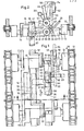
- FIG. 1 and 2 show the chain elements 12, 13 of a transport chain 10 connected to rods 11.
- a connecting element 14 and a supporting element 15 are rotatably mounted on the rods 11.
- the connecting element 14 carries near its free end 14a a support rod 16 with which the support element 15, which is under the force of a spring 17 'in the sleeve 17, is supported with the spacer 18 in the operative position.
- the spacer 18 is held on the support element 15 with a carrier 19 displaced forward in the transport direction.
- a support tube 20 is also rigidly fastened to this support 19, with which, as will be described later, the spacer part 18 is held in the inoperative position.
- two further pivot axes 21 and 22 are arranged one above the other on the support element 15. While the overhead pivot axis 22nd is rotatably mounted, the underlying pivot axis 21 serves as a bearing for the button element 30.
- This button element 30 is articulated by means of a lever arm 31 on the pivot axis 21, so that it comes to rest on the one hand under the carrier 19 and on the other hand a small stroke with a relatively large stroke Rotation of the pivot hub 32 causes.
- a catch rod 33 is arranged on the pivot hub 32 approximately diagonally with respect to the lever arm 31. This catch rod 33 has a catch nose 34 with a catch edge 35.
- a latching tab 40 which is rigidly connected to the pivot axis 22 by means of the swivel housing 42, interacts with the catch edge 35 in order to hold the button element 30 in the operative position.
- a slight lifting of the button element 30 causes the catch 34 to rotate, and the catch edge slides under the catch flag 40 in a clockwise direction.
- the pivot hub 32 acts in a counterclockwise direction and the lever arm 31 is thus pressed against the support bolt 41.
- Another spring 42 'in the swivel housing 42 rotates it and the swivel axis 22 clockwise until the support lug 51 bears against the support rod 55. Due to the action of this further spring 42 ', the locking lug 40 presses with a sliding surface 43 against the catching edge 35 and thus the force of the spring 36 1 in the housing 36 is overcome and the button element 30 is suddenly raised.
- the detent lug 40 releases the catch edge 35 and the button element 30 is pushed through the spring in the housing 36 is rotated counterclockwise, again from the position shown in broken lines, into the position shown in the extended position and thus comes into the operative position.
- the movement of the deflection flag 44 can be brought about by a run-up rail 50.
- a support lug 51 is also rigidly connected to the pivot axis 22. This support lug 51 is used to place the support tube 20 in order to hold the spacer 18 in the disengaged position. So that the support tube 20 can be lifted up, an idler roller 52 is fastened to the support element 15 by means of an arm 53. Another run-up rail 54 serves to press down this run-up roller 52, so that the support element 15 is thus rotated relative to the connecting element 14. Thus, if the support element 15 is first rotated by means of the run-up rail 54 and the run-up roller 52 and then the deflection flag 44 is pressed to the left, the support flag 51 can undertake the support tube 20 'and the spacer 18 and the button element 30 are in the inoperative position.
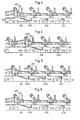
- Fig. 3 shows two objects GI and G2, which rest on spacers 118 and 218.
- the conveyor belt moves at a first speed to the right in the drawing according to arrow B and the chain above it moves at a lower speed, which can be about half as large, also to the right according to arrow C.
- the objects Gl, G2 thus close to the spacers 118, 218.
- the associated button elements 130 and 230 are in the inoperative position. In the following arrangement, both the spacer 318 and the button element 330 are in the operative position.
- the support lug 351 underpins the support tube 420.
- the object G3 transported at a higher speed now reaches the button element 330 according to FIG. 4 and begins to lift it.
- the pushbutton element is flipped up and the supporting lug 351 releases the supporting tube 420, and the spacer 418 and the pushbutton element 430 come into the operative position, as shown in FIG. 5.
- the button element 330 is not yet completely out of action.
- the button element 30 is not only raised, but also rotated at the same time, so that it cannot impair the object G3 when it is transported against the spacer 318.
- FIG. 6 show the state when the object G3 is abutted on the spacer 318 and is now at the same distance from the object G2 as this object G2 from the object G1 in FIG. 3.
Landscapes
- Engineering & Computer Science (AREA)
- Mechanical Engineering (AREA)
- Control Of Conveyors (AREA)
- Attitude Control For Articles On Conveyors (AREA)
- Pusher Or Impeller Conveyors (AREA)
- Feeding Of Articles To Conveyors (AREA)
Applications Claiming Priority (2)
| Application Number | Priority Date | Filing Date | Title |
|---|---|---|---|
| CH1831/83 | 1983-04-05 | ||
| CH1831/83A CH659222A5 (de) | 1983-04-05 | 1983-04-05 | Vorrichtung zum ordnen von gegenstaenden in eine reihe mit gleichen abstaenden. |
Publications (2)
| Publication Number | Publication Date |
|---|---|
| EP0121501A2 true EP0121501A2 (fr) | 1984-10-10 |
| EP0121501A3 EP0121501A3 (fr) | 1986-02-19 |
Family
ID=4219619
Family Applications (1)
| Application Number | Title | Priority Date | Filing Date |
|---|---|---|---|
| EP84810162A Withdrawn EP0121501A3 (fr) | 1983-04-05 | 1984-04-03 | Dispositif pour ranger les objets sur une ligne de façon équidistante |
Country Status (4)
| Country | Link |
|---|---|
| US (1) | US4609095A (fr) |
| EP (1) | EP0121501A3 (fr) |
| JP (1) | JPS59190109A (fr) |
| CH (1) | CH659222A5 (fr) |
Cited By (1)
| Publication number | Priority date | Publication date | Assignee | Title |
|---|---|---|---|---|
| EP0496093A1 (fr) * | 1990-12-21 | 1992-07-29 | Union Carbide Chemicals And Plastics Company, Inc. | Catalyseur à haute activité à base de vanadium |
Families Citing this family (7)
| Publication number | Priority date | Publication date | Assignee | Title |
|---|---|---|---|---|
| DE3708881C1 (de) * | 1987-03-19 | 1988-10-13 | Haensel Otto Gmbh | Verfahren und Vorrichtung zum Ausrichten von Suesswarenstuecken |
| GB8708368D0 (en) * | 1987-04-08 | 1987-05-13 | Tweedy Of Burnley Ltd | Aligning & spacing articles |
| US10361802B1 (en) | 1999-02-01 | 2019-07-23 | Blanding Hovenweep, Llc | Adaptive pattern recognition based control system and method |
| US8352400B2 (en) | 1991-12-23 | 2013-01-08 | Hoffberg Steven M | Adaptive pattern recognition based controller apparatus and method and human-factored interface therefore |
| ES2076112B1 (es) * | 1993-09-23 | 1998-03-16 | Vilar Alberto Vila | Perfeccionamientos en las maquinas para la seleccion de elementos discoidales de corcho. |
| US7966078B2 (en) | 1999-02-01 | 2011-06-21 | Steven Hoffberg | Network media appliance system and method |
| US6305525B1 (en) | 1999-10-27 | 2001-10-23 | Delta Systems, Inc. | Pressureless infeed conveyor table |
Family Cites Families (5)
| Publication number | Priority date | Publication date | Assignee | Title |
|---|---|---|---|---|
| GB889419A (en) * | 1957-05-17 | 1962-02-14 | Emi Ltd | Improvements in or relating to conveyors |
| US3162294A (en) * | 1962-07-05 | 1964-12-22 | R A Jones & Company Inc | Article timing mechanism for packaging machines |
| US3266614A (en) * | 1964-03-25 | 1966-08-16 | Nat Biscuit Co | Article spacing system |
| US3335841A (en) * | 1966-03-11 | 1967-08-15 | Klingel Erwin | Method and apparatus for feeding articles to a packaging machine |
| CH540180A (de) * | 1971-05-17 | 1973-08-15 | Sig Schweiz Industrieges | Förderanlage mit Vorrichtung zum Trennen von in gegenseitiger Berührung auf einem Eingangsförderer zulaufenden Gegenständen, z.B. länglichen Schokoladeblöcken |
-
1983
- 1983-04-05 CH CH1831/83A patent/CH659222A5/de not_active IP Right Cessation
-
1984
- 1984-03-22 JP JP59053653A patent/JPS59190109A/ja active Pending
- 1984-04-03 EP EP84810162A patent/EP0121501A3/fr not_active Withdrawn
- 1984-04-05 US US06/597,018 patent/US4609095A/en not_active Expired - Fee Related
Cited By (1)
| Publication number | Priority date | Publication date | Assignee | Title |
|---|---|---|---|---|
| EP0496093A1 (fr) * | 1990-12-21 | 1992-07-29 | Union Carbide Chemicals And Plastics Company, Inc. | Catalyseur à haute activité à base de vanadium |
Also Published As
| Publication number | Publication date |
|---|---|
| US4609095A (en) | 1986-09-02 |
| CH659222A5 (de) | 1987-01-15 |
| JPS59190109A (ja) | 1984-10-27 |
| EP0121501A3 (fr) | 1986-02-19 |
Similar Documents
| Publication | Publication Date | Title |
|---|---|---|
| DE69207350T2 (de) | Gerät zum Sortieren von kugelförmigen Produkten nach Gewicht | |
| DE2438440C3 (de) | Vorrichtung zum reihenweisen Einsetzen von Eiern mit abwärtsweisendem spitzerem Ende in Aufnahmezellen von Verpackungsbehältern | |
| DE2065252C3 (de) | Vorrichtung zum Vereinzeln von Bogen eines Bogenstapel | |
| CH648223A5 (de) | Vorrichtung zum ueberfuehren von abgelaengten draehten aus einem losen drahtbuendel in eine einfachlage von parallelen draehten. | |
| EP0121501A2 (fr) | Dispositif pour ranger les objets sur une ligne de façon équidistante | |
| DE2614659C3 (de) | Bandförderweiche | |
| DE2820957A1 (de) | Ausschleusvorrichtung | |
| DE605130C (de) | Vorrichtung zum Aussondern einzelner Bogen in der Auslage von Druckmaschinen o. dgl.von Hand | |
| DE1756420A1 (de) | Vorrichtung zum schrittweisen Ausladen aus hinteremander herbewegten Behaeltern | |
| DE2715194B2 (de) | Vorrichtung zum Schwenken einer sich horizontal auf einem Luftkissentisch bewegenden Glasscheibe in ihrer Ebene | |
| EP0218804B1 (fr) | Dispositif pour reprendre et transférer des feuilles pliées d'un dispositif de transport | |
| DE3907037C2 (de) | Vorrichtung zur Bogenlängenabfrage in einer Bogen bearbeitenden Maschine | |
| DE2504306C3 (de) | Vorrichtung zum Wenden von auf einer Transporteinrichtung stehenden Gegenständen | |
| CH666703A5 (de) | Rotations-schaftmaschine. | |
| DE2614531C2 (de) | Vorrichtung zum Umsetzen langgestreckter Erzeugnisse | |
| EP1149036B1 (fr) | Dispositif permettant de desassembler une pile d'objets plats, en particulier de produits d'imprimerie | |
| DE2716904C3 (de) | Übergabeeinrichtung für rollbare Gegenstände | |
| DE2932860C2 (de) | Vorrichtung zum Abtasten der Anwesenheit eines Bonbons | |
| DE3026910C2 (de) | Kluppe für Spann- und Reckmaschinen | |
| DE4101436A1 (de) | Vorrichtung zum ablegen von kopieblaettern | |
| DE932727C (de) | Vorrichtung zum selbsttaetigen Einstellen der Stapelhoehe am Stapeltisch einer bogenverarbeitenden Maschine mittels Fuehlers | |
| DE559438C (de) | Rotationsdruckmaschine fuer veraenderliche Formate zum Verarbeiten von endlosen Werkstoffbahnen aus Papier o. dgl. | |
| DE19522831C2 (de) | Vorrichtung zum Transportieren von Weichpackungen | |
| DE2052418C3 (de) | Staurollenbahn | |
| DE835889C (de) | Vorrichtung zum Abheben des obersten Bogens von einem Stapel mittels Saugern |
Legal Events
| Date | Code | Title | Description |
|---|---|---|---|
| PUAI | Public reference made under article 153(3) epc to a published international application that has entered the european phase |
Free format text: ORIGINAL CODE: 0009012 |
|
| AK | Designated contracting states |
Designated state(s): DE FR GB IT NL |
|
| PUAL | Search report despatched |
Free format text: ORIGINAL CODE: 0009013 |
|
| AK | Designated contracting states |
Designated state(s): DE FR GB IT NL |
|
| 17P | Request for examination filed |
Effective date: 19860527 |
|
| 17Q | First examination report despatched |
Effective date: 19861121 |
|
| STAA | Information on the status of an ep patent application or granted ep patent |
Free format text: STATUS: THE APPLICATION IS DEEMED TO BE WITHDRAWN |
|
| 18D | Application deemed to be withdrawn |
Effective date: 19881103 |
|
| RIN1 | Information on inventor provided before grant (corrected) |
Inventor name: LENHERR, HARALD Inventor name: DEUTSCHLAENDER, GERT |