EP0121593A2 - Système optique pour faire une image sur un support électrophotographique - Google Patents
Système optique pour faire une image sur un support électrophotographique Download PDFInfo
- Publication number
- EP0121593A2 EP0121593A2 EP83109918A EP83109918A EP0121593A2 EP 0121593 A2 EP0121593 A2 EP 0121593A2 EP 83109918 A EP83109918 A EP 83109918A EP 83109918 A EP83109918 A EP 83109918A EP 0121593 A2 EP0121593 A2 EP 0121593A2
- Authority
- EP
- European Patent Office
- Prior art keywords
- lens
- scan line
- fine
- image
- radiant energy
- Prior art date
- Legal status (The legal status is an assumption and is not a legal conclusion. Google has not performed a legal analysis and makes no representation as to the accuracy of the status listed.)
- Withdrawn
Links
Images



Classifications
-
- H—ELECTRICITY
- H04—ELECTRIC COMMUNICATION TECHNIQUE
- H04N—PICTORIAL COMMUNICATION, e.g. TELEVISION
- H04N1/00—Scanning, transmission or reproduction of documents or the like, e.g. facsimile transmission; Details thereof
- H04N1/04—Scanning arrangements, i.e. arrangements for the displacement of active reading or reproducing elements relative to the original or reproducing medium, or vice versa
- H04N1/19—Scanning arrangements, i.e. arrangements for the displacement of active reading or reproducing elements relative to the original or reproducing medium, or vice versa using multi-element arrays
- H04N1/191—Scanning arrangements, i.e. arrangements for the displacement of active reading or reproducing elements relative to the original or reproducing medium, or vice versa using multi-element arrays the array comprising a one-dimensional [1D] array
- H04N1/1911—Simultaneously or substantially simultaneously scanning picture elements on more than one main scanning line, e.g. scanning in swaths
-
- H—ELECTRICITY
- H04—ELECTRIC COMMUNICATION TECHNIQUE
- H04N—PICTORIAL COMMUNICATION, e.g. TELEVISION
- H04N1/00—Scanning, transmission or reproduction of documents or the like, e.g. facsimile transmission; Details thereof
- H04N1/04—Scanning arrangements, i.e. arrangements for the displacement of active reading or reproducing elements relative to the original or reproducing medium, or vice versa
- H04N1/047—Detection, control or error compensation of scanning velocity or position
- H04N1/053—Detection, control or error compensation of scanning velocity or position in main scanning direction, e.g. synchronisation of line start or picture elements in a line
-
- H—ELECTRICITY
- H04—ELECTRIC COMMUNICATION TECHNIQUE
- H04N—PICTORIAL COMMUNICATION, e.g. TELEVISION
- H04N1/00—Scanning, transmission or reproduction of documents or the like, e.g. facsimile transmission; Details thereof
- H04N1/04—Scanning arrangements, i.e. arrangements for the displacement of active reading or reproducing elements relative to the original or reproducing medium, or vice versa
- H04N1/113—Scanning arrangements, i.e. arrangements for the displacement of active reading or reproducing elements relative to the original or reproducing medium, or vice versa using oscillating or rotating mirrors
- H04N1/1135—Scanning arrangements, i.e. arrangements for the displacement of active reading or reproducing elements relative to the original or reproducing medium, or vice versa using oscillating or rotating mirrors for the main-scan only
-
- H—ELECTRICITY
- H04—ELECTRIC COMMUNICATION TECHNIQUE
- H04N—PICTORIAL COMMUNICATION, e.g. TELEVISION
- H04N1/00—Scanning, transmission or reproduction of documents or the like, e.g. facsimile transmission; Details thereof
- H04N1/387—Composing, repositioning or otherwise geometrically modifying originals
- H04N1/3871—Composing, repositioning or otherwise geometrically modifying originals the composed originals being of different kinds, e.g. low- and high-resolution originals
-
- H—ELECTRICITY
- H04—ELECTRIC COMMUNICATION TECHNIQUE
- H04N—PICTORIAL COMMUNICATION, e.g. TELEVISION
- H04N1/00—Scanning, transmission or reproduction of documents or the like, e.g. facsimile transmission; Details thereof
- H04N1/04—Scanning arrangements, i.e. arrangements for the displacement of active reading or reproducing elements relative to the original or reproducing medium, or vice versa
- H04N1/12—Scanning arrangements, i.e. arrangements for the displacement of active reading or reproducing elements relative to the original or reproducing medium, or vice versa using the sheet-feed movement or the medium-advance or the drum-rotation movement as the slow scanning component, e.g. arrangements for the main-scanning
-
- H—ELECTRICITY
- H04—ELECTRIC COMMUNICATION TECHNIQUE
- H04N—PICTORIAL COMMUNICATION, e.g. TELEVISION
- H04N2201/00—Indexing scheme relating to scanning, transmission or reproduction of documents or the like, and to details thereof
- H04N2201/04—Scanning arrangements
- H04N2201/047—Detection, control or error compensation of scanning velocity or position
- H04N2201/04701—Detection of scanning velocity or position
- H04N2201/0471—Detection of scanning velocity or position using dedicated detectors
-
- H—ELECTRICITY
- H04—ELECTRIC COMMUNICATION TECHNIQUE
- H04N—PICTORIAL COMMUNICATION, e.g. TELEVISION
- H04N2201/00—Indexing scheme relating to scanning, transmission or reproduction of documents or the like, and to details thereof
- H04N2201/04—Scanning arrangements
- H04N2201/047—Detection, control or error compensation of scanning velocity or position
- H04N2201/04701—Detection of scanning velocity or position
- H04N2201/04734—Detecting at frequent intervals, e.g. once per line for sub-scan control
-
- H—ELECTRICITY
- H04—ELECTRIC COMMUNICATION TECHNIQUE
- H04N—PICTORIAL COMMUNICATION, e.g. TELEVISION
- H04N2201/00—Indexing scheme relating to scanning, transmission or reproduction of documents or the like, and to details thereof
- H04N2201/04—Scanning arrangements
- H04N2201/047—Detection, control or error compensation of scanning velocity or position
- H04N2201/04701—Detection of scanning velocity or position
- H04N2201/04744—Detection of scanning velocity or position by detecting the scanned beam or a reference beam
- H04N2201/04746—Detection of scanning velocity or position by detecting the scanned beam or a reference beam after modulation by a grating, mask or the like
Definitions
- the field of the invention comprises apparatus and a method for imaging electrophotographic members by means of radiant energy devices such as lasers, the imaged electrophotographic members being thereafter used for printing.
- the actual imaged member itself is treated to render toned and untoned parts hydrophobic and hydrophilic respectively and the member comprises the plate without further processing.
- the.toned electrophotographic member may be used as an information source by reading the images or projecting them if transparent or photographically reproducing them if desired.
- the preferred use of the invention is to make the printing plates upon metal such as stainless steel. Each of these substrates is coated with a type of photoconductive coating which will be described hereinbeiow.
- Forming printing plates carrying both graphics and text images may involve several-steps, especially when color graphics are to be reproduced.
- several color separation plates must be made for each color to be printed with the text information located on the plate in which color is to be printed.
- additional steps are required to form the solid printing areas for the plates in that particular color and to remove the graphics image from those same text areas on the remainder of the color separation plates. This of course adds to the number of processed steps required to produce the desired graphics and text images.
- the steps of forming the graphics image to be printed in the graphics field is commonly known as overburning while the process of removing the graphics image from those same text areas in the other color separation plates to be printed is referred to or is commonly known as stripping.
- the apparatus and method of the present invention overcome these drawbacks presented by the manual and electronics systems by xphx providing a system which in one pass of a beam of radiant energy may form both graphics and text images in response to graphics and text data input thereto. Formation of the graphics and text images may occur independently of one another so that different imaging schemes may be used to form scaled densities of the graphics images and the binary densities of the text images.
- Formatting of the data is such that the graphics data contains information related to the relative scale densities of incremental areas of the graphics image with the remainder of the graphics data-being a nullity to clear the surface of a charged electrophotographic member.
- the text data is formated such that it does not affect the formation of the images carried by the graphics data except in locations where text images are to be formed.
- Formation of text images within the field of graphics images for several different color separation plates is performed simply by reversing the logical sense of a control bit of every text data digital word.
- the same data may be used for all of the color separation plates with dz the control xxy bit for the color separation plate used to print the color blue set to one logical state and being set to the other logical state for the remainder of the separation plates.
- the apparatus and method of the invention provide for imaging of an entire printing plate with graphics and text information in a single pass of a beam of radiant energy.
- the apparatus and method of the invention include an optical system in which a beam of radiant energy from a monochromatic source such as a laser is used to selectively discharge and leave charged incremental areas of a charged electrophotographic member. Part of the beam is split and used as a reference beam. The remainder of the beam is modulated to provide a scanning beam or a fine beam comprised of individual rays of radiant energy with each ray able to discharge an incremental of the member.
- the reference beam and scanning beam or fine beam are aligned vertically with one another with the vertical alignment being used in an optical grating system to precisely determine the location of the scanning beam along the surface of the member.
- a field flattening lens is used in which both ' the reference and fine beams passed therethrough and back again to the member, the field flattening lens providing the maintenance of a focused image on the surface of the member across every scan line.
- a digital plate maker system and apparatus which receives binary digital graphics and text data to form a toned latent image on electrophotographic member, the toned image thereafter being fused to the member and the member being used as a printing plate in an offset lithographic printing press.
- the plate maker system including an optical system, an electronics system and a toning system.
- the optical system providing 22 individual rays of radiant energy with which to discharge incremental areas of the electrophotographic member.
- the optical system further providing field flattening to maintain a focused image of the individual rays across every scan line across the original image.
- An optical scale or grating system is provided which receives a reference beam of radiant energy vertically aligned with a fine.beam which may be comprised of the 22 individual rays, the bar collector receiving-the reference beam across the length of every scan line.
- the bar collector directs the radiant energy from the reference beam to a sensor which provides electrical signals indicating the position of the fine beam along the scan line.
- a method of forming the text and graphics images on the member is implemented in electronic system.
- the graphic data is used to generate beam modulation signals to form the desired number of xndx individual rays.
- the text data is used to modulate the beam modulation signals so that text images . may be overlayed on graphic images or formed outside of fields of graphics images.
- the imaging device receives digital data representing the graphics and text images to be printed or otherwise reproduced.
- This digital data is received from a compiling system which obtains raw data from such as optical scanning system,'text input stations, etc., and compiles or formats the data representing the graphics and text materials into a form which may be used by the imaging device of the invention herein.
- the data received by the imaging device also may be generated or synthesized by a computer, or by other means and may be presented to the imaging device from a memory in which it has been stored or it may be presented on line as it is generated or synthesized if equal to or less than the imaging rate of an imaging device herein.
- the output of the imaging device herein is an electrophot o - graphic member carrying a toned latent image of charged andxxdxx discharged incremental areas formed in response to the digital data.
- the toned member thereafter may be fused and processed for use as a printing plate in an offset lithographic printing press with the toned areas carrying ink to a receptor to form the tonal graphics and text images. If color printing is desired, as many electro- photographic members carrying toned latent images are formed, as there are colors which are desired to be printed, one member carrying a toned latent image for each of what is commonly known as a color separation.
- the imaging device or imager used in the preferred embodiment of this invention uses a la er beam to image an electrophotographic member that includes a photoconductive coating that previously has been charged.
- the member is carried on a rotary drum, is toned on the drum and thereafter may be used to transfer the toned image or to servce as a medium for projection or printing of the image.
- the toned image is used to carry ink in a printing press, the member having been treated to achieve hydrophilic and hydrophobic areas to enable offset lithographic use of member as a printing plate.
- the preferred use of the imaged member herein is as a printing plate and has the same type of photoconductive imagable coating is preferably the receptor of the lazar beams which comprise the output xux from the apparatus of the invention.
- Such coating is that which is described and claimed in U.S. Patent 4,025,339.
- the apparatus and method of the invention may best be understood by considering that the binary digital data input binarily to the apparatus is used to modulate a beam of radiant energy from a lazar to selectively discharge and leave changed incremental areas of a charged electrophotographic member. Thereafter, the selectively charged and discharged pattern or image carried on the member is toned and output from the apparatus.
- the electrophotographic member is carried on the outer circumference of a drum which is rotated along its longitudinal axis. Charging, imaging and toning of the member on the drum occurs sequentially at adjacent stations as the member is move past the stations by the rotating drum. Charging of the electro- photographic member may be of any means desired and in the preferred embodiment occurs by placing adjacent the outer circumference of the drum a wire chaving a high voltage applied thereto- Toning of the imaged member occurs by applying to the member a quantity of carrier fluid obtaining toner particles. The charging and'toning occurring at stations respectively above and below an imaging plane.
- Imaging of the charged electrophotographic member occurs by passing a fine beam of radiant energy from a lazer across the surface of the sas member in image lines which are parallel to the longitudinal axis of the drum and lie in the imaging plane. Imaging of the entire surface of the charged member occurs in sequential image lines as the member is moved by the drum past the imaging plane.
- the digital input to the imaging apparatus is in the . form of two channels of graphics data and one channel of text data.
- Each digital word of the graphics data is used to form a picture element or a graphics pixel on the electrophotographic member.
- Every imaging line is comprised of two scan lines of graphics pixels with each channel of graphic's data respectively controlling the forming of graphics pixels in one scan line.
- the text data controls the formation of text pixels across the entire scan line and therefore only one channel of text data is required. Every word of the text data is comprised of 8-bits of information with the least significant six bits each controlling the binary density of a text pixel, the next least significant bit serving as a control bit, and the most significant bit not being used.
- the graphics data and text data are formated such that they may individually form respective graphics or text images across the entire area of the electrophotographic member.
- the electronics of the invention herein uses both text and graphics data to form one channel of laser modulation signals. Further, in the imaging apparatus herein, the information carried by the text data is used to gate the formation of- the individual ray s of the fine beam of radiant energy, each of which rays are used to discharge an incremental area on the charged electro- photographic member.
- the text data is used to gate or modulate the formation of graphics pixels in response to the graphic data-
- the text data is a nullity, no text images are to be formed on the member, the information carried by the graphics data will form the graphic image represented thereby and discharge the remaineder of the member.
- the text data may either inhibit the formation of individual rays of the fine beam or depending on the logical state of the control bit included in each word of text data.
- the text data inhibits the formation of individual rays of the fine beam
- the text image is formed on the member which will be toned and in the printing plate will carry ink to the receptor to print a solid image. This is a case where black text is desired on any background
- the text data forms individual rays of the fine beam, text pixels are discharged on the member with the discharged areas of the member forming areas of the printing plate which do not print on the receptor or which remain clear. This is the case where clear text is desired within a graphics image.
- the text pixels are nine times more numerous than the graphics pixels, i.e., for every graphics pixel, there are nine text pixels which may be discharged or left charged.
- the resolution provided by the text pixels is nine times not however the resolution provided by the graphics pixels because of overlap of the text pixels.
- the electrophotgraphic member is not physically divided into pixels of any type, scan lines or image lines, and that these terms are used only. to describe the operation of the imaging apparatus and method.
- Fig. 1 of the drawings the apparatus of the invention there is illustrated diagrammatically is indicated generally by the reference character 30.
- Two channels of graphics data are received by the apparatus respectively on channel A and channel B graphics data buffers 32 and 34.
- Text data is received into text data buffer 36.
- the graphics data contained in data buffers 32 and 34 individually are applied to pattern generators 38 and 40 over leads 42 and 44.
- pattern generators 38 and 40 the density information carried by the digital words of the graphics data are converted into patterns of elements which are to be formed in graphics pixels on the member, graphics data. the pixel patterns representing the densities indicated by the
- pattern information produced by pattern generators 3 8 and 4 0 then is applied to modulator 46 on leads 48 and 50 together with the text data from text data buffer 36 on lead 52.
- modulator 46 the text data is xu used to modulate the pattern information from pattern generators 38 and 40.
- the output of modulator 46 which is applied to acousto-optic modulator 54 is the ray data which controls the formation of individual : rays in the fine beam.
- the output of modulator 46 is carried to the acousto-optic modulator 54 on lead 56.
- a radiant energy source 58 is provided which produces a beam of radiant energy 60 which essentially at one wave length and which is directed to acousto-optic modulator 54.
- Radiant energy source 58 is in the preferred embodiment a lazar with the wave length of the beam of radiant energy 60 being chosen to most advantageously discharge area of the electrophotographic member.
- Acousto-optic modulator 54 modulates the beam of radiant energy 60 to provide a fine beam 62 of radiant energy comprised of a plurality of individual rays and in some cases as little as a single ray.
- the fine beam 62 is directed onto an electrophotographic member 64 carried on a drum 66 rotating in the direction indicated by arrow 68.
- the thickness of member 64 is exagerated in Fig. 1 only so that member 64 may easily be seen on the circumference of drum 66.
- Charging of member 64 occurs at charging station 70 prior to the time at which fine beam 62 is applied to amember 64 and toning of member 64 occurs after imaging by fine beam 62 at station 72.
- the apparatus 30 includes an optical cabinet 80 which encloses a left-hand optical system 82 and a right hand optical system 84.
- Drum 66 extends the width of the left-hand and right-hand optical systems 82 and 84 so that an electrophotographic member carried thereon may be simultaneously and separately imaged by respective optical systems.
- Drum 66 is supported at each end by supports 86 and 88 and is rotationally driven by motor 90.
- the drum is enclosed by a housing 92, which protects a member carried on drum 66 from ambient light.
- Optical cabinet 80 and housing 92 adjoin each other there being only a small slit opening between them through which the fine beam passes on its way to the charged electrophotographic member.
- the electrophotographic member is held on drum 66 by a magnetic chuck which is formed ofna magnetic strips extending the length of drum 66 at the circumference thereof.
- the magnetic field produced by these magnetic strips is strong enough so that an electrophotographic member having a substrate of such as stainless steel will be securely held on the drum.
- the drum circumference is 125 0 mm. while the drum length is 1, 100.mm.
- the drum is continuously rotated at a speed of 0.125RPM which corresponds to 180 revolutions per day or 8 minutes per revolution. This provides a drum speed of 2.6 mm per second.
- the center line of the charging station 70 is arranged to be 25 degrees above the image plane, while the center line of the toning station 72 is arranged to be 30 degrees below the imaging plane.
- the maximum size electrophotographic member which may be carried by the drum 66 is a member which is 1.040 by 1.040 mm and the area of the member which may be imaged by each of the left and right hand optical systems is 5 0 cm. axial of the drum by 70 cm. circumferential of the drum or an area which is 20 X 28 inches.
- a cabinet 94 is provided in which the toning tanks and pumps are contained with the hydraulic and nomadic connections between cabinet 94 and toning station 72 (not shown in the drawings for clarity purposes.)
- Mounted on the exterior of cabinet 80 are two lazers 96 and 98, which provide the radiant energy respectively to the left-hand and right-hand optical systems 82 and 84.
- the entire apparatus 30 is supported by a frame 100 having the general configuration of a table.
- Auxillary equipment for operating the apparatus 30 such as power supplies for the lazers 96 and 98 serve or control electronics for the motor 90 and auxillary tanks for the toning system may be be mounted under frame 100, and are not shown in Fig. 2 for clarity of the drawing.
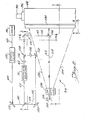
- lazer 96 provided the beam of radiant energy 60 to special filter 110 which provides what may be termed a pinhole aperture to obtain a desired cross-sectional size of the beam.
- the beam 60 is transmitted through spatial filter 110 to folding mirror 112 which deflects beam 60 to beam splitter 114.
- a nxo portion of beam 60 is transmitted through beam splitter 114 and forms a reference beam 118 which is deflected by folding mirror 120 and 122 to a spot forming lens 124.
- the portion of beam 60 which is deflected by beam splitter 114 is directed to acousto-optic deflector 54 which forms of beam 60 the individual rays which have been refered to as the fine beam 62.
- Fine beam 62 exits acousto-optic deflector 54 and passes through spot forming lens 126 and passes under folding mirror 128.
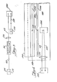
- Reference beam 118 passes through spot forming lens 124 as deflected by folding mirror 128. After fine beam 62 passes under folding mirror 128, fine beam 62 and reference beam 118 are vertically aligned with one another through the remainder of the optical path. Referring to Fig.
- reference beam 11 8 which is transmitted through beam splitter 114 is represented by a crossed line indicating the light in reference beam 118 is exiting the drawing figure.
- Folding mirror 128 also is shown in Fig. 5 located above fine beam 62 after it passes through spot forming lens 126 and the circle at the center of folding mirror 128 representing that reference beam 118 is directed into drawing fig.5.Fine beam 62 and reference beam 118 then are deflected by folding mirror 130 with the crossed lines in Fig. 5 on folding mirror 130 indicating the light is exiting from the drawing figure while the xu circles on folding mirror 130 on Fig. 6 indicate that the light is entering the drawing figure.
- Fine beam 62 and reference beam 118 then are passed through a relay lens 132 to a folding mirror 134. Again the crossed lines on folding mirror 134 on Fig. 6 representing that the beams are exiting the drawing figure.
- beams 62 and 118 are deflected by folding mirror 134 through an f ⁇ lens system 136 to a galvanometer mirror 1 38 .
- Galvanometer mirror 138 is rotatatbly oscillated in the directions indicated by arrow 142 and directs fine beam 62 back . through the f ⁇ lens system 136 through an aperture 144 extending through the front plate 146 of cabinet 80 and then onto the charged electrophotographic member 64.
- Reference beam 11 8 is deflected by galvanometer mirror 138 back through f 6 lens system 136 and onto a folding mirror 148 to an optical scale or grating system 150.
- Galvanometer mirror 138 deflects fine beam 62 through a scan line 152 illustrated in Fig. 6 and deflects reference beam 118 along a scan line 154 lying on deflecting mirror 148.
- the extent to which the galvanomter mirror deflects fine beam 62 and reference beam 118 are represented in Fig. 4 by dashed lines 156.
- fine beam 62 and reference beam 118 are located below the imaging plane defined by fine beam 62 as it passes through aperture 1 4 . 4 and is directed onto electrophotographic member 64.
- the F ⁇ lens lens system 136 provides field flattening for both fine beam 62 and reference beam 118 so that they may be maintained in focus respectively across the surface of the electrophotographic member 64 and across the surface of the optical scale or grating system 150. It will be noted that the distance travelled by fine beam 62 along an optical path from spot focusing lens 1 26 to member 64 is equal to the distance travelled along the optical path by reference beam 118 from spot forming lens 124 to optical scale or grating system 150.
- spacial filter or folding mirrors, beam splitters, spot forming lenses, relay lens and galvanometer mirror are all common optical elements which readily may be contructed and arranged in a system as has been described as may be desired.
- this spot forming lenses have a focal length of 26 mm
- the relay lens has a focal length of 200 mm
- the F 9 system has a focal length of 87 0 m m .
- the distance between the spot forming lens and the relay lens is 559.2 mm while the distance between the relay lens and the F ⁇ lens is 1,190 mm.
- the distance from the F 6 system to the focal plane at the electrophotographic member 64 and the optical scale system 150' is of course 870 mm.
- the f 0 lens system 136 is illustrated in Fig. 8 and comprises elements Ll through L4 having surfaces defined by radii Rl through R8 as shown.
- the lens of Fig. 8 comprises from the object end a first positive group L1, L2 having a concave object side surrace; a second positive group L3 having a flat object side surface; and a third positive group L4 having a flat object side surface and a convex image side surface.
- the lens of Fig. 8 is defined substantially by the data of Table I, as scaled to a focal length of 870 mm;
- the lens disclosed may of course be scaled otherwise as is desired.
- the acous t o -optic deflector 54 is capable of separating beam 60 into as many as 22 individual rays or beamlets which form fine beam 62.
- as many as 22 individual radio' frequency signals may be applied to acousto-optic deflector 54 to deflect the 22 individual rays each radio. frequency signal being capable of deflecting one individual ray.
- Acousto-optical deflector 54 is constructed and arranged so that the individual which rays/are deflected from beam 60 are aligned vertically in fine beam 62 and so that in the focused images formed on the electro-photographic member 64 are arranged adjacent and spaced equidistant from one another.
- a radio' frequency signal of the first frequency will form one individual ray while the next radial frequency signal will form an adjacent ray and so on.
- acousto-optic deflector 54 is capable of deflecting 22 individual rays and although deflector 54 operates on the principle of acoustically deflecting the individual rays other deflection apparatus may be used in place of.
Landscapes
- Engineering & Computer Science (AREA)
- Multimedia (AREA)
- Signal Processing (AREA)
- Mechanical Optical Scanning Systems (AREA)
- Combination Of More Than One Step In Electrophotography (AREA)
Priority Applications (1)
| Application Number | Priority Date | Filing Date | Title |
|---|---|---|---|
| EP83109918A EP0121593A3 (fr) | 1980-04-11 | 1981-04-10 | Système optique pour faire une image sur un support électrophotographique |
Applications Claiming Priority (3)
| Application Number | Priority Date | Filing Date | Title |
|---|---|---|---|
| US06/139,462 US4408868A (en) | 1980-04-11 | 1980-04-11 | Digital plate maker system and method |
| US139462 | 1980-04-11 | ||
| EP83109918A EP0121593A3 (fr) | 1980-04-11 | 1981-04-10 | Système optique pour faire une image sur un support électrophotographique |
Related Parent Applications (2)
| Application Number | Title | Priority Date | Filing Date |
|---|---|---|---|
| EP81102773.9 Division | 1981-04-10 | ||
| EP81102773A Division EP0038497B1 (fr) | 1980-04-11 | 1981-04-10 | Procédé de production d'images dans un élément électrophotographique et dispositif de mise en oeuvre du procédé |
Publications (2)
| Publication Number | Publication Date |
|---|---|
| EP0121593A2 true EP0121593A2 (fr) | 1984-10-17 |
| EP0121593A3 EP0121593A3 (fr) | 1984-11-28 |
Family
ID=26088065
Family Applications (1)
| Application Number | Title | Priority Date | Filing Date |
|---|---|---|---|
| EP83109918A Withdrawn EP0121593A3 (fr) | 1980-04-11 | 1981-04-10 | Système optique pour faire une image sur un support électrophotographique |
Country Status (1)
| Country | Link |
|---|---|
| EP (1) | EP0121593A3 (fr) |
Family Cites Families (9)
| Publication number | Priority date | Publication date | Assignee | Title |
|---|---|---|---|---|
| US3727062A (en) * | 1972-03-10 | 1973-04-10 | Zenith Radio Corp | Acousto-optic information translation system with reference beam for control purposes |
| US3868167A (en) * | 1973-01-15 | 1975-02-25 | Massachusetts Inst Technology | Electro-optical communication of visual images |
| JPS588B2 (ja) * | 1975-10-15 | 1983-01-05 | 富士写真フイルム株式会社 | ヒカリビ−ムソウサソウチ |
| US4004079A (en) * | 1975-11-14 | 1977-01-18 | Optronics International, Inc. | Method and apparatus for dual resolution photographic reproduction of line and continuous tone graphic materials |
| GB2005440B (en) * | 1977-09-26 | 1982-02-03 | Hewlett Packard Co | Laser scanning system having automatic orthogonal scan deviation correction |
| JPS54111362A (en) * | 1978-02-20 | 1979-08-31 | Canon Inc | Two-dimensional scanning optical system |
| US4257053A (en) * | 1979-02-09 | 1981-03-17 | Geosource, Inc. | High-resolution laser plotter |
| US4468706A (en) * | 1979-02-13 | 1984-08-28 | Coulter Systems Corporation | Imaging by varying the placement of elements in the pixels |
| US4306242A (en) * | 1980-03-18 | 1981-12-15 | Data General Corporation | Laser recording system |
-
1981
- 1981-04-10 EP EP83109918A patent/EP0121593A3/fr not_active Withdrawn
Also Published As
| Publication number | Publication date |
|---|---|
| EP0121593A3 (fr) | 1984-11-28 |
Similar Documents
| Publication | Publication Date | Title |
|---|---|---|
| US4422099A (en) | Optical communication on variable power beam | |
| EP0124641A1 (fr) | Collecteur d'énergie radiant pour l'utilisation dans un système de grille optique | |
| EP0079958B1 (fr) | Appareil d'adressage optique de haute resolution | |
| US4467334A (en) | Laser beam printer | |
| EP0012952B2 (fr) | Système de balayage par rayon laser | |
| US4768043A (en) | Optical system for changing laser beam spot size during scanning of scanning line | |
| US3944323A (en) | Variable spot size scanning system | |
| US4060323A (en) | Image information handling method and device | |
| CA2018931C (fr) | Systeme de balayage optique a faisceaux lasers multiples | |
| US4476474A (en) | Dot recording apparatus | |
| US4393411A (en) | Laser read-write system for the production of engravings | |
| GB1509439A (en) | Multifunction scanning system | |
| US4499437A (en) | Apparatus and method providing improved control of a laser beam | |
| WO1989012369A1 (fr) | Systeme de scanner a laser multi-faisceau | |
| US4060322A (en) | Image information handling device | |
| JPS58150978A (ja) | レ−ザプリンタにおけるレ−ザ光源駆動方法 | |
| US4419676A (en) | Method of recording signals on bands by means of laser beams and apparatus for carrying out the method | |
| EP0137559B1 (fr) | Dispositif d'exposition | |
| US4493549A (en) | Optical system for imaging an electrophotographic member | |
| US4928118A (en) | Enhanced resolution electrophotographic-type imaging station | |
| JP3528091B2 (ja) | 光ビームにより記録用媒体を走査する装置 | |
| JP3090892B2 (ja) | デジタルハーフトーン画像の印刷を改善する方法および装置 | |
| US4439789A (en) | Binary scan system | |
| US5493325A (en) | Graduation reproduction in optical recording | |
| US4504126A (en) | Digital plate maker system and method |
Legal Events
| Date | Code | Title | Description |
|---|---|---|---|
| PUAI | Public reference made under article 153(3) epc to a published international application that has entered the european phase |
Free format text: ORIGINAL CODE: 0009012 |
|
| PUAL | Search report despatched |
Free format text: ORIGINAL CODE: 0009013 |
|
| AC | Divisional application: reference to earlier application |
Ref document number: 38497 Country of ref document: EP |
|
| AK | Designated contracting states |
Designated state(s): BE CH DE FR GB IT LI NL |
|
| AK | Designated contracting states |
Designated state(s): BE CH DE FR GB IT LI NL |
|
| 17P | Request for examination filed |
Effective date: 19850514 |
|
| 17Q | First examination report despatched |
Effective date: 19870311 |
|
| STAA | Information on the status of an ep patent application or granted ep patent |
Free format text: STATUS: THE APPLICATION HAS BEEN WITHDRAWN |
|
| 18W | Application withdrawn |
Withdrawal date: 19870615 |
|
| RIN1 | Information on inventor provided before grant (corrected) |
Inventor name: KRAMER, GEORGE H. Inventor name: KEANE, JOHN F. Inventor name: TIBBITS, JOHN L. Inventor name: THOMAS, RAYMOND E. |