EP0121608A2 - Cellule électrolytique du type vertical et procédé électrolytique utilisant celle-ci - Google Patents
Cellule électrolytique du type vertical et procédé électrolytique utilisant celle-ci Download PDFInfo
- Publication number
- EP0121608A2 EP0121608A2 EP83113194A EP83113194A EP0121608A2 EP 0121608 A2 EP0121608 A2 EP 0121608A2 EP 83113194 A EP83113194 A EP 83113194A EP 83113194 A EP83113194 A EP 83113194A EP 0121608 A2 EP0121608 A2 EP 0121608A2
- Authority
- EP
- European Patent Office
- Prior art keywords
- cathode
- cell
- plate
- compartment
- perforated
- Prior art date
- Legal status (The legal status is an assumption and is not a legal conclusion. Google has not performed a legal analysis and makes no representation as to the accuracy of the status listed.)
- Withdrawn
Links
Images




Classifications
-
- C—CHEMISTRY; METALLURGY
- C25—ELECTROLYTIC OR ELECTROPHORETIC PROCESSES; APPARATUS THEREFOR
- C25B—ELECTROLYTIC OR ELECTROPHORETIC PROCESSES FOR THE PRODUCTION OF COMPOUNDS OR NON-METALS; APPARATUS THEREFOR
- C25B1/00—Electrolytic production of inorganic compounds or non-metals
- C25B1/01—Products
- C25B1/34—Simultaneous production of alkali metal hydroxides and chlorine, oxyacids or salts of chlorine, e.g. by chlor-alkali electrolysis
- C25B1/46—Simultaneous production of alkali metal hydroxides and chlorine, oxyacids or salts of chlorine, e.g. by chlor-alkali electrolysis in diaphragm cells
-
- C—CHEMISTRY; METALLURGY
- C25—ELECTROLYTIC OR ELECTROPHORETIC PROCESSES; APPARATUS THEREFOR
- C25B—ELECTROLYTIC OR ELECTROPHORETIC PROCESSES FOR THE PRODUCTION OF COMPOUNDS OR NON-METALS; APPARATUS THEREFOR
- C25B9/00—Cells or assemblies of cells; Constructional parts of cells; Assemblies of constructional parts, e.g. electrode-diaphragm assemblies; Process-related cell features
- C25B9/13—Single electrolytic cells with circulation of an electrolyte
-
- C—CHEMISTRY; METALLURGY
- C25—ELECTROLYTIC OR ELECTROPHORETIC PROCESSES; APPARATUS THEREFOR
- C25B—ELECTROLYTIC OR ELECTROPHORETIC PROCESSES FOR THE PRODUCTION OF COMPOUNDS OR NON-METALS; APPARATUS THEREFOR
- C25B9/00—Cells or assemblies of cells; Constructional parts of cells; Assemblies of constructional parts, e.g. electrode-diaphragm assemblies; Process-related cell features
- C25B9/17—Cells comprising dimensionally-stable non-movable electrodes; Assemblies of constructional parts thereof
- C25B9/19—Cells comprising dimensionally-stable non-movable electrodes; Assemblies of constructional parts thereof with diaphragms
Definitions
- the present invention generally relates to an electrolytic cell partitioned by an ion exchange membrane into an anode compartment and a cathode compartment and electrolytic process using the electrolytic cell. More specifically, it relates to an electrolytic cell in which a cathode compartment is separated by a non-perforated cathode plate into a gas generation room and a gas separation room and electrolytic process for carrying out electrolysis while removing a cathode gas generated on the cathode plate substantially perfectly by causing a circulating flow to occur between the gas generation room and the gas separation room by gas lift effect.
- a parforated cathode in electrolysing an aqueous alkali metal chloride solution by an electrolytic cell providing an ion exchange membrane, a parforated cathode has been mostly employed.
- the perforated cathode typical are expanded metal sheets, punched metal sheets and metal screens.
- cathode gas generated on the cathode surface ascends between the ion exchange membrane and the cathode, and the other part of it passes through perforations to the backside of the cathode and ascends.
- residence of cathode gas generated on the cathode in the vicinity of the cathode, especially in a space between the cathode and the membrane leads to an increase of electric resistance in liquid, thus resulting in increased cell voltage.
- Japanese Patent Non-examined Publication No. 114571/1977 discloses a process in which an expanded metal sheet is used as a cathode and the long axis of perforations is allowed to have a specific angle (0 to 45 degrees ) . Nonetheless, even the foregoing cathode fails to prevent the presence of cathode gas in a small gap between the cathode and the membrane, when the anode-cathode distance is not more than 2mm, especially 1mm, thereby resulting in an increase in cell voltage.
- Japanese Patent Non-examined Publication No.56193/1978 dicloses a process in which partition plates are located behind the cathode and the electrolysis is effected while allowing a circulating flow to occur naturally or forcibly
- 46483 / 1978 discloses an electrolytic cell having the construction in which a catholyte inlet is provided at an upper portion of a cathode compartment and the downward flow is caused to take place by inertia of catholyte inlet flow in the cathode compartment, whereby the downward flow is introduced to behind a separating barrier through the lower portion of the barrier while cathode gas generated on a perforated cathode are eliminated behind the cathode
- 81498/1978 proposes an electrolytic cell in which a louver type cathode comprising up-grade-bars extended toward a membrane is employed and catholyte is caused to flow from behind the cathode to thus form the circulating flow.
- Japanese Patent Non-examined Publication No, 23076 /1982 teaches a process for preventing the adhesion of gas bubbles by providing a-electro-conductive porous layer with gas and liquid permeability on the surface of the membrane.
- This process involves the difficulty to be applied to an industrial scale electrolytic cell,namely, it is by no means easy to form the electro-conductive porous layer uniformly on the surface of a large membrane.
- no effect is expected as to the aim of rapidly removing gas present on the surface of the cathode.
- Japanese Patent Non-examined Publication No.116891/ 1981 it is proposed that the adhesion of gas is prevented by rendering the surface of the membrane rough, but the foregoing problems are not yet solved.
- the present invention encompasses an electrolytic cell characterized in that a cathode compartment is divided by a non-perforated cathode plate into two rooms a gas generation room and a gas separation room, said two rooms being communicated through opened portions provided at the substantially uppermost and lowermost parts of said cathode plate, and further electrolytic process characterized in that using the foregoing electrolytic cell, an upward flow of catholyte is caused to take place by gas lift effect of cathode gas generated in the gas generation room to form a mixed stream of the cathode gas and the catholyte, said mixed stream is introduced through the opened portion at the uppermost part of the cathode plate into the gas separation room where the cathode gas is separated from the catholyte, then the catholyte with smaller gas content than the mixed stream in the gas generation room is introduced again into the gas generation room through the opened portion at the lowermost part of the cathode plate, whereby a circulating flow is allowed to occur between the gas generation room and
- the finger type electrolytic cell herein used may not only involve a finger tyie construction cell such as described at page 93, CHLORINE-Its Manufacture, Properties And Uses, edited by J.S.Sconce, issued by Reinhold Publishing Corporation, New York, 1962, but a flattened tube type construction cell.
- the present invention is not only applied to the finger type electrolytic cell but to a filter press type electrolytic cell.
- a cation exchange membrane is used in various shapes such as sheet, envelope, cylinder and the like.
- the horizontal cross-sectional area of the gas separation room is at least about twice, preferably about 5 times the horizontal cross-sectional area of the gas generation room.
- the upper limit is not specifically limited, but 500 or 1000 times or more result in disadvantages such as an increase in equipment cost and therefore it is determined taking into those disadvantages.
- the residence of cathode gas is prevented, the adhesion of cathode gas onto the surfaces of the cathode plate and the membrane is eliminated, and thus the electrolysis is effected with low cell voltage,through which power consumption is reduced.
- conventional perforated cathodes such as an expanded metal sheet
- the portion of the membrane close to the metallic portions of the cathode is in high current density while the portion of the membrane close to the hollow portions is in low current density, in consequence, non-uniform current distribution is brought about to thus cause an increase in cell voltage.
- the cathode used in the present invention is non-perforated, having no hollow portions in itself, and hence uniform current distribution is obtained. Accordingly, current distribution of the membrane also becomes to be uniform and low cell voltage is obtained.
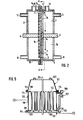
- FIG.2 is a schematic vertical sectional . view of an electrolytic cell of the present invention and FIG.3 is a cross-sectional view taken on line A-A of FIG.2.
- FIG.4 is a cross-sectional view of another embodiment taken on line A-A of FIG.2.
- the cathode compartment is separated by a non-perforated cathode plate 1 into a gas generation room 7a and a gas separation room 7b, said gas generation room being surrounded by a cation exchange membrane 4, cathode compartment side walls and a membrane-opposing surface la of the cathode plate 1 and said gas separation room 7b being surrounded by a backside 1b of the cathode plate 1, cathode compartment side walls 5, said both rooms being communicated through opened portions 2 and 3.
- the cation exchange membrane used suitably in the present invention includes, for example, membranes made of perfluorocarbon polymers having cation exchange groups.
- the membrane made of a perfluorocarbon polymer containing sulfonic acid groups is sold by E.I. Du Pont de Nemours& Company under the trademark "NAFION" having the following chemical structure ;
- the equivalent weight of such cation exchange membranes is preferred in a range between 1,000 and 2,000, more preferably in a range between 1,100 and 1,500..
- the equivalent weight herein means weight (g ) of a dry membrane per equivalent of an exchange group.
- membranes whose sulfonic acid groups are substituted, partly or wholly, by carboxylic acid groups and other membranes widely used can also be applied to the present invention.
- These cation exchange membranes exhibit very small water permeability so that they permit the passage of only sodium ion containing three to four molecules of water, while hindering the passage of hydraulic flow.
- the front surface of the non-perforated cathode plate 1, namely the surface 1a opposing to the cation exchange membrane 4 is substantially flat.
- the non-perforated cathode plate 1 may preferably be made of iron, stainless steel, nickel and the like and it is a preferred embodiment to coat the surface with platinum group metal, electroconductive oxides, iron group metals or the like with a view to reducing hydrogen overvoltage.
- the backside of the non-perforated cathode plate, namely, the surface 1b not opposing to the cation exchange membrane may be coated with rubbers, heat-resistant plastics and the like or subjected to nickel plating, nickel plasma flame spray and the like to prevent the corrosion.
- the distance between the non-perforated cathode plate 1 and the cation exchange membrane 4 is not specifically limited, but preferably not more than about 5mm, especially not more than about 2mm. The smaller the distance between the two becomes, the higher the speed of the upward flow becomes.
- cathode gas generated on the front surface la of the cathode plate 1 is enfolded in catholyte to thus form a mixed stream and the mixed stream goes up as an upward flow of high speed thanks to gas-lift effect, then overflows from an upper opened portion 2 into the gas separation room 7b.
- the gas-liquid mixed stream overflowed is subjected to gas-liquid separation in the gas separation room 7b to be electrolyte (catholyte ) with low content of gas and the electrolyte goes down ,then is introduced to the gas generation room through a lower opened portion 3.
- Forcible circulating by pump and the like may be suitably applied to the present invention, if necessary. That is.
- the shape of the upper and lower opened portions 2 and 3 is not specifically limited, including such as a horizontally long rectangular shape and a shape of round holes arranged in a row horizontally.
- the non-perforated cathode plate 1 may be allowed to include minute holes, slits, small gaps formed between the both sides of the cathode plate and the cathode compartment side walls.
- the surface 1a to the side of the cathode gas generation room of the non-perforated cathode plate may be such a degree as could be regarded as flat macroscopically such as a cathode plate treated with plasma flame spray with about 10 micron meter-nickel fine pasrticles.
- the surface la may be also permitted to be of a concave-convex structure having protuberances extending vertically. Moreover, the surface la may be provided with small protrusions at suitable distances.
- the concave-convex structure may be given by shaving off a flat plate to'thus form ditches in parallel to one another, welding a plurality of thin rods such as round rods and square rods to a flat plate or by uniting protuberances and a flat plate.
- the cathode may be fabricated from a corrugated plate.
- the corrugation may be in any form such as rectangular, trapezoidal, sinusoidal, cycloidal and circular shapes, or mixtures thereof or partially deformed shapes thereof.
- the concave-convex structure need not necessarily be continuous to a longitudinal way and may be intermittent for the purpose.
- the non-perforated cathode plate of concave-convex structure it is a preferred embodiment to position the cathode . plate in such a manner that the convexities are in close proximity of or in contact with the cation exchange membrane.
- the protuberances serve as a guide rail by which cathode gas is introduced upwardly.
- the liquid level in the gas separation room 7b may be permitted to be above or below the upper opened portion 2.
- the removal of cathode gas and catholyte may be effected according to the conventional technology.
- the anode, a counter electrode of the non-perforated cathode plate may be fabricated from an expanded metal sheet of valve metals such as titanium, niobium and tantalum or alloys thereof coated with platinum group metals, electroconductive oxides or electroconductive reducing oxides therof.
- valve metals such as titanium, niobium and tantalum or alloys thereof coated with platinum group metals, electroconductive oxides or electroconductive reducing oxides therof.
- the cathode used in the present invention is non-perforated and therefore results in the uniformity of current distribution.
- the conventional anodes used for ion exchange membrane cells or asbestos diaphragm cells are fabricated from titanium expanded sheets having perforations with the largest diameter of about 8.mm and the smallest diameter of about 3 mm and the perforation rate of 50 %.
- the diameters of perforations of the anodes had best be made smaller. 'By so doing, microscopic electric current distribution between the anodes and the cathodes is made uniform and cell voltage is lowered.
- the largest diameter should preferably be about 5 mm or less, or the smallest diameter . should preferably be about 2 mm or less.
- the clearance between the adjacent rods should preferably be about 2 mm or less.
- low cell voltage is generally attained by keeping the membrane colser to the anode than the cathode.
- a space for permitting the gas-liquid stream to ascend is required between the cathode and the membrane and a change in distance between the cathode and the membrane during the electrolysis is not desired because it places influence on circulation speed of the catholyte, in consequence, adhesion of bubbles.
- it is desired to hold the uniform distance between the cathode and the membrane by pressing the membrane against the anode side.
- the pressing of the membrane against the anode side is achieved, for example, by raising presssure in the cathode compartment higher than that in the anode compartment.
- anode which is fabricated from a non-perforated plate of valve metals treated with coating as aforesaid may also be suitably employed.
- the cation exchange membrane 4 is secured to compartment walls 5, 18 with interposition of corrosion-resistant gaskets 15 to thus form the cathode compartment 7 and the anode compartment 17 partitioned by the membrane 4.
- the non-perforated cathode plate 1 and the perforated anode 16 are secured by conducting rods 6, 8 so as to face each other from both sides of the membrane 4.
- An aqueous sodium chloride solution is supplied through an - anolyte inlet 10 and electrolyzed on the anode 16, then chlorine gas generated is removed through anode gas outlet 14. Depleted anolyte is discharged through an anolyte outlet,12.
- a catholyte inlet 9 water or diluted caustic soda solution introduced into the cathode compartment 7, electrolyzed on the front surface la of the non-perforated cathode plate to generate hydrogen gas.
- Hydrogen gas generated is discharged through a cathode gas outlet 13 and concentrated caustic soda solution is discharged through a catholyte outlet 11.
- gas outlets 14 and 13 are omitted, respectively.
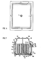
- FIG. 5 is a schematic longitudinal sectional view illustrating a typical monopolar finger type asbestos diaphragm electrolytic cell in use for the electrolysis of an aqueous alkali chloride solution and
- FIG. 6 is a dissassembled perspective view of the cell shown by FIG. 5.
- a finger type asbestos diaphragm electrolytic cell is comprised of an FRP top cover 101, as shown by FIG.6 (A), a cathode box 102, as shown FIG. 6 (B ) and a bottom plate of copper 103 as shown by FIG. 6- (C ) .
- the top cover 101 is equipped with a concentrated brine inlet 104 and a chlorine gas outlet 105.
- the cathode box 102 is equipped with a hydrogen gas outlet 106 and'a caustic soda solution outlet 107 and further fingers 108 or flattened tubes 108 (hereinafter referred to as "fingers 108 ”) located vertically in a parallel row.
- the fingers 108 are fabricated from iron meshes, lath boards, perforated plates and the like and secured by welding to one ends of substantially horizontal plates 109, positioned at upper and lower portions, the other ends of the plates 109 being secured by welding to upper and lower flanges 111 of side walls 110, to thus form the cathode box 102 by the fingers 108, plates 109 and side walls 110.
- the plates 109 are made of the same material with the fingers 108 and the both are working surfaces on which electrolysis takes place.
- anode structures 112 are embedded vertically in a parallel row.
- top cover 101 cathode box 102 and bottom plate 103
- a rubber sheet 113 is placed on the bottom plate 103 for anticorrosion and then the cathode box 102 is secured to the bottom plate 103 with interposition of a packing 114. That is, the anode structures 112 are fixed into substantially central portions of spaces formed by the adjacent fingers 108 so that the working surfaces of the fingers 108 face those of the anode structure 112 vertically in a parallell row at a distance of several millimeters to ten and several millimeters. Then, the top cover 101 is placed on the cathode box 102 with a packing 114.
- FIG. 7 and FIG. 8 show a converting process of existing asbestos diaphragm electrolytic cell to an ion exchange membrane electrolytic cell according to the present invention.
- a depleted brine outlet 115 installed to the top cover 101 .
- the outlet 115 is preferably positioned to as low portion as possible of the top cover 101 and depleted brine after electrolysis is discharged by overflowing form the outlet 115.
- a water supply inlet 116 is installed to the side walls 110.
- an existing device such as a drain outlet at a lower portion of the side walls, said existing device may also be utilized.
- the water supply inlet . 116 Through the water supply inlet . 116,.is pure water or circulating catholyte introduced to thus control concentration of caustic soda produced.
- FIG. 6 of the cathode box 102 Fingers 108 in FIG. 6 of the cathode box 102 are removed.
- the plates 109 in FIG. 6 may be removed simultaneously or may be remained as they are.
- FIG. 7 and FIG. 8 illustrate an example in which the plates 109 were removed.
- non-perforated cathode plates 117 are set up.
- the non-perforated cathode plates 117 are made of alkali-resistant materials such as iron, stainless steel, nickel alloys, chrome alloys, iron plated with nickel and the like.
- the backside of the non-perforated cathode plates 117 may preferably be coated further with alkali-resistant materials, since, while the working surfaces, i.
- the inside surfaces of the side wall 110 of the cathode box 102 may also preferably be coated with alkali-resistant materials.
- alkali-resistant materials nickel plating, rubber lining, epoxy resin coating, fluorocarbon resin coating and the like may be suitably served.
- the - surfaces of cathode gas generation room sides of the non-perforated cathode plates 117 are subjected to treatment of low hydrogen overvoltage.
- the surfaces of the cathode gas generation room sides may be those as could be macroscopically identified with flat surface, just as a cathode plate subjected to plasma flame spray with nickel fine particles of about 10 ⁇ m diameter or may be those having a concave-convex structure with protuberances extending vertically, Moreover, the surfaces may be provided with small protrusions at suitable distances.
- the non-perforated cathode plates 117 are secured by welding or mechanical means to securing plates (not shown ) with which the side walls 110 are equipped so that upper opened portions 123 and lower opened portions 124 are formed respectively. When the plates 109 are not removed, the cathode plates 117 may be secured thereto by welding or mechanical means.
- the cathode plates 117 with a size suitable for formation of the upper and lower opened portions may be used, and further plates having, at upper and lower portions, opened portions of circular, elliptical, rectangular and other shapes may also be used.
- the bottom plate 103 requires no remodeling but the anode structures 112 may be changed to expandable anodes shown by Japanese Patent Examined Publication No. 35031 /1975.
- cation exchange membranes 118 cylindrically formed are installed to the cathode box 102 through an upper support frame 119 and a lower support frame 120.
- Processes for forming cylindrical cation exchange membranes are disclosed by Japanese Patent Non-examined Publication Nos. 145540 / 1930, 152191/1980 and the like, and installation processes of cylindrically formed cation exchange membranes to electarolytic cell are described by Japanese Utility Model Non-examined Publication No. 100952/1979 and the like.
- the rubber sheet 113 is placed for corrosion prevention, and the cathode box 102 providing ion exchange membranes by the use of the upper and lower support frames 119, 120 are set up on the rubber sheet 113 and tightly sealed.
- the anode structures 112 are put in the substantially central parts of the cylindrical ion exchange membranes 118 so that the working surfaces of the non-perforated cathode plates 117, the ion exchange membranes 118 and the working surfaces of the anode structures 112 stand face to face with one another at an interval of several millimeters to zero.
- the top cover 101 is set up on the upper portion of the cathode box 112 through the packing 114.
- a converted electrolytic cell is therefore constructed which is separated into an anode compartment 121 and a cathode compartment 122 by the ion exchange membnrane 118, the upper support frame 119 and the lower support frame 120, said cathode compartment being partitioned by the non-perforated cathode plate 117 into a cathode gas generation room 122a and a gas separation room 122b, said both rooms being in communication with each other through the uppermost and the lowermost opened portions 123 and 124.
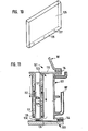
- FIG. 9 is a sectional view of the principal part of the electrolytic cell shown by FIG. 7.
- FIG. 10 is a perspective view of a cation exchange membrane 125 formed in an envelope shape having an upper opened portion.
- the envelope-shaped cation exchange membrane has at its bottom 126 a hole 127 through which an anode electro-conducting rod is allowed to pass and fixed to the bottom plate through a flange-with which the bottom plate is provided.
- FIG. 11 is a sectional view of the principal part of a box type electrolytic cell to which the envelope-shaped cation exchange membrane 125 depicted by FIG. 10 was installed.
- the upper portion of the cation exchange membrane 125 is secured to the upper support frame 119 by hot melt bonding, adhesive bonding, mechanical means and the like.
- electrolyte with smaller gas content obtained by being separated from cathode gas at the gas separation room 122b is supplied through the lower opened portion 124.
- the horizontal cross-sectional area of the gas separation room 122b is determined such that adequate gas-liquid separation not only takes place, but electrolyte with small gas content is supplied through the lower opened portion 124.
- the horizontal cross-sectional area of the gas separation room 122b should have at least about twice or more, more preferably about 5 times the horizontal cross-sectional area of the gas generation room 122a.
- the electrolytic cell of the present invention may, of course, be newly constructed.
- an aqueous sodium chloride solution is supplied through the inlet 104 into the anode compartment 121 and electrolyzed on the anode structure 112. Chlorine gas generated on the anode is discharged through the outlet 105. On the other hand, depleted brine electrolyzed is removed through the outlet 115.
- water supply inlet 116 is water or diluted agueous caustic soda solution introduced into the cathode compartment 122 and electrolyzed on the front surface of the non-perforated cathode plate 117 to thus generate hydrogen gas.
- Hydrogen gas thus generated goes up with the circulating flow of caustic soda solution in the cathode gas generation room 122a and transported to the cathode gas separation room 122b where hydrogen gas is separated from caustic soda solution and discharged through the outlet 106, while concentrated caustic soda solution being removed through the outlet 107.
- NATION 901 (Registered trademark, manufactured and sold by E. I. Du Pont de Nemours & Company ) was installed to an electrolytic cell having an working area of 100 mm width and 700 mm height.
- a non-perforated cathode plate a flat plate of SUS 304 with the thickness of 3 mm was used. The front surface of the cathode plate was subjected to plasma spray with nickel fine particles to be a low hydrogen overvoltage cathode. The distance between the backside of the cathode and the cathode compartment was 30 mm.
- As an anode a titanium expanded metal coated with solid solution of ruthenium oxide and titanium oxide was used. The anode had perforations having the largest diameter of about 8 mm, the smallest diameter of about 3.5 mm, whose perforation rate was about 46 %.
- the membrane was positioned so that the distance between the membrane and the cathode plate was 1.5 mm and that the membrane was in contact with the anode.
- anode compartment Into the anode compartment a 5 N NaCl aqueous solution was supplied and into the cathode compartment water was supplied, and the electarolysis was carried out at 80 °C while keeping NaCl concentration in the anode compartment at 3.5 N, caustic soda concentration in the cathode compartment at 32% and the cathode compartment gas pressure higher than the anode compartment gas pressure by 200 mmH 2 O.
- Cell voltage was 3.09 V at current density of 30 A/d m 2 and current efficiency was 96 %. The operation was further continued for one month but cell voltage was held constant.
- Cell voltage was 3.04 V at current density of 30 A /d m 2 and current efficiency was 96 %.
- the electrolysis was effected in a similar manner to that of Example 1, excepting that the distance between the backside of the non-perforated cathode plate and the cathode compartment wall was varied to 1 mm, 5 mm, 15 mm, respectively.
- the electrolysis was conducted in a similar manner to that of Example 1, with the exception that the lower opened portion was closed.
- Cell voltage was 3.17 V at current density of 23.5 A /d m 2 .
- an iron cathode box having the inner dimensions of 700 mm height, 260 mm width and 900 mm length, two iron flat plates, each having 12 mm thickness, 660 mm height and 900 mm length, were secured to be served as cathode plates at an interval of 57 mm (between the two plates, an anode is to be placed) by welding the one end of plates to the cathode box and by bolting the other end.
- the three surfaces of the cathode box were beforehand coated with a hard rubber in the thickness of 5 mm and the one surface, to which the cathode plates were secured, was subjected to chemical plating with nickel including welded portions.
- the two flat plates were, prior to be secured to the cathode box, subjected to chemical plating with nickel at entire surfaces, then the surfaces opposing to the anode were subjected to plasma spray with nickel fine particles in the thickness of 200 ⁇ m.
- cation exchange membrane support frames of titanium were positioned, to which frames "NAFION 901" formed cylindrically was installed.
- the distance between the upper and lower support frames and the upper or lower end of the cathode plates, i. e., the height of the opened portions provided at upper and lower portions of the cathode plates was 10 mm.
- an expandable DSA 686 mm high and 622 mm wide, was inserted and the cathode-anode distance was adjusted to 2 mm.
- the expandable DSA had perforations with the largest diameter of about 3 mm, the smallest diameter of about 1.5 mm and the perforation rate of about 20 %.
- Electric power was supplied so that current density became 23.5 A/d m 2 , with controlling depleted brine concentration to 3.5N, catholyte concentration to 32 %, temperature to 85 °C and the cathode compartment gas pressure higher than the anode compartment gas pressure by 200 mmH 2 O.
- the operation was contined for three months.
- Current efficiency and cell voltage were 95.5 % and 3.04 V, respectively on the average.
Landscapes
- Chemical & Material Sciences (AREA)
- Engineering & Computer Science (AREA)
- Chemical Kinetics & Catalysis (AREA)
- Electrochemistry (AREA)
- Materials Engineering (AREA)
- Metallurgy (AREA)
- Organic Chemistry (AREA)
- Inorganic Chemistry (AREA)
- Electrolytic Production Of Non-Metals, Compounds, Apparatuses Therefor (AREA)
Applications Claiming Priority (2)
| Application Number | Priority Date | Filing Date | Title |
|---|---|---|---|
| JP58064324A JPS59190379A (ja) | 1983-04-12 | 1983-04-12 | 縦型電解槽及びそれを用いる電解方法 |
| JP64324/83 | 1983-04-12 |
Publications (2)
| Publication Number | Publication Date |
|---|---|
| EP0121608A2 true EP0121608A2 (fr) | 1984-10-17 |
| EP0121608A3 EP0121608A3 (fr) | 1985-08-28 |
Family
ID=13254940
Family Applications (1)
| Application Number | Title | Priority Date | Filing Date |
|---|---|---|---|
| EP83113194A Withdrawn EP0121608A3 (fr) | 1983-04-12 | 1983-12-29 | Cellule électrolytique du type vertical et procédé électrolytique utilisant celle-ci |
Country Status (4)
| Country | Link |
|---|---|
| US (1) | US4574037A (fr) |
| EP (1) | EP0121608A3 (fr) |
| JP (1) | JPS59190379A (fr) |
| IN (1) | IN161963B (fr) |
Cited By (4)
| Publication number | Priority date | Publication date | Assignee | Title |
|---|---|---|---|---|
| EP0311575A1 (fr) * | 1987-10-06 | 1989-04-12 | Siam Trade Equipment Co., Ltd. | Cellule d'électrolyse et procédé de production de chlore |
| EP0383243A3 (fr) * | 1989-02-13 | 1991-08-21 | De Nora Permelec S.P.A. | Electrolyseur pour l'électrolyse chlore-alcali et anode |
| DE4224492C1 (de) * | 1992-07-24 | 1993-12-09 | Uhde Gmbh | Vorrichtung zum elektrolytischen Behandeln von Flüssigkeiten mit einer Anoden- und einer Kathodenkammer sowie deren Verwendung |
| CN106835185A (zh) * | 2017-04-07 | 2017-06-13 | 河北华普化工设备科技有限公司 | 过硫酸盐电解生产装置 |
Families Citing this family (50)
| Publication number | Priority date | Publication date | Assignee | Title |
|---|---|---|---|---|
| US4767511A (en) * | 1987-03-18 | 1988-08-30 | Aragon Pedro J | Chlorination and pH control system |
| US4875988A (en) * | 1988-08-05 | 1989-10-24 | Aragon Pedro J | Electrolytic cell |
| US5348664A (en) * | 1992-10-28 | 1994-09-20 | Stranco, Inc. | Process for disinfecting water by controlling oxidation/reduction potential |
| US20040035696A1 (en) * | 2002-08-21 | 2004-02-26 | Reinhard Fred P. | Apparatus and method for membrane electrolysis for process chemical recycling |
| US7390399B2 (en) * | 2004-12-21 | 2008-06-24 | Siemens Water Technologies Holding Corp. | Water treatment control systems and methods of use |
| US20060169646A1 (en) * | 2005-02-03 | 2006-08-03 | Usfilter Corporation | Method and system for treating water |
| US7905245B2 (en) * | 2005-09-30 | 2011-03-15 | Siemens Water Technologies Corp. | Dosing control system and method |
| US8046867B2 (en) | 2006-02-10 | 2011-11-01 | Tennant Company | Mobile surface cleaner having a sparging device |
| US8025787B2 (en) | 2006-02-10 | 2011-09-27 | Tennant Company | Method and apparatus for generating, applying and neutralizing an electrochemically activated liquid |
| EP2207631A2 (fr) * | 2007-10-04 | 2010-07-21 | Tennant Company | Procédé et appareil pour neutraliser des liquides activés de façon électrochimique |
| US8635985B2 (en) * | 2008-01-07 | 2014-01-28 | Mcalister Technologies, Llc | Integrated fuel injectors and igniters and associated methods of use and manufacture |
| US8365700B2 (en) * | 2008-01-07 | 2013-02-05 | Mcalister Technologies, Llc | Shaping a fuel charge in a combustion chamber with multiple drivers and/or ionization control |
| US7628137B1 (en) * | 2008-01-07 | 2009-12-08 | Mcalister Roy E | Multifuel storage, metering and ignition system |
| US8225768B2 (en) * | 2008-01-07 | 2012-07-24 | Mcalister Technologies, Llc | Integrated fuel injector igniters suitable for large engine applications and associated methods of use and manufacture |
| US8074625B2 (en) * | 2008-01-07 | 2011-12-13 | Mcalister Technologies, Llc | Fuel injector actuator assemblies and associated methods of use and manufacture |
| US8387599B2 (en) * | 2008-01-07 | 2013-03-05 | Mcalister Technologies, Llc | Methods and systems for reducing the formation of oxides of nitrogen during combustion in engines |
| US8413634B2 (en) * | 2008-01-07 | 2013-04-09 | Mcalister Technologies, Llc | Integrated fuel injector igniters with conductive cable assemblies |
| US8561598B2 (en) * | 2008-01-07 | 2013-10-22 | Mcalister Technologies, Llc | Method and system of thermochemical regeneration to provide oxygenated fuel, for example, with fuel-cooled fuel injectors |
| KR20110053948A (ko) * | 2008-06-19 | 2011-05-24 | 텐난트 컴파니 | 동축 전극을 포함하는 튜브형 전기분해 전지 및 그 대응 방법 |
| MX2010014393A (es) * | 2008-06-19 | 2011-03-24 | Tennant Co | Celda de electrolisis con electrodos con aperturas de varios tamaños/formas. |
| US8075750B2 (en) * | 2009-02-17 | 2011-12-13 | Mcalister Technologies, Llc | Electrolytic cell and method of use thereof |
| RU2484182C2 (ru) * | 2009-02-17 | 2013-06-10 | МАКЭЛИСТЭР ТЕКНОЛОДЖИЗ, ЭлЭлСи | Электролитическая ячейка и способ ее применения |
| SG173719A1 (en) | 2009-02-17 | 2011-09-29 | Mcalister Technologies Llc | Apparatus and method for gas capture during electrolysis |
| KR101352231B1 (ko) | 2009-02-17 | 2014-01-15 | 맥알리스터 테크놀로지즈 엘엘씨 | 전기분해 중에 핵화를 제어하기 위한 장치 및 방법 |
| US9040012B2 (en) | 2009-02-17 | 2015-05-26 | Mcalister Technologies, Llc | System and method for renewable resource production, for example, hydrogen production by microbial electrolysis, fermentation, and/or photosynthesis |
| JP5563660B2 (ja) * | 2009-08-27 | 2014-07-30 | マクアリスター テクノロジーズ エルエルシー | セラミック絶縁体並びにその使用及び製造方法 |
| CA2772044C (fr) | 2009-08-27 | 2013-04-16 | Mcalister Technologies, Llc | Mise en forme d'une charge de carburant dans une chambre de combustion a l'aide de plusieurs systemes d'entrainement et/ou de commande d'ionisation |
| KR20120086375A (ko) | 2009-12-07 | 2012-08-02 | 맥알리스터 테크놀로지즈 엘엘씨 | 연료 인젝터 및 점화기를 위한 적응 제어 시스템 |
| KR101364416B1 (ko) | 2009-12-07 | 2014-02-17 | 맥알리스터 테크놀로지즈 엘엘씨 | 대형 엔진 적용에 적합한 일체식 연료 인젝터 점화기 및 연관된 이용 및 제조방법 |
| EP2534347B1 (fr) | 2010-02-13 | 2016-05-04 | McAlister, Roy Edward | Procédés et systèmes de refroidissement adaptatif de chambres de combustion dans des moteurs |
| WO2011100701A2 (fr) | 2010-02-13 | 2011-08-18 | Mcalister Roy E | Ensembles injecteurs de combustible comprenant des modificateurs de force acoustique, et procédés d'utilisation et de fabrication associés |
| US20110297753A1 (en) | 2010-12-06 | 2011-12-08 | Mcalister Roy E | Integrated fuel injector igniters configured to inject multiple fuels and/or coolants and associated methods of use and manufacture |
| US8528519B2 (en) | 2010-10-27 | 2013-09-10 | Mcalister Technologies, Llc | Integrated fuel injector igniters suitable for large engine applications and associated methods of use and manufacture |
| US8091528B2 (en) | 2010-12-06 | 2012-01-10 | Mcalister Technologies, Llc | Integrated fuel injector igniters having force generating assemblies for injecting and igniting fuel and associated methods of use and manufacture |
| US8820275B2 (en) | 2011-02-14 | 2014-09-02 | Mcalister Technologies, Llc | Torque multiplier engines |
| US8919377B2 (en) | 2011-08-12 | 2014-12-30 | Mcalister Technologies, Llc | Acoustically actuated flow valve assembly including a plurality of reed valves |
| CN103890343B (zh) | 2011-08-12 | 2015-07-15 | 麦卡利斯特技术有限责任公司 | 用于改进的发动机冷却及能量产生的系统和方法 |
| US8851047B2 (en) | 2012-08-13 | 2014-10-07 | Mcallister Technologies, Llc | Injector-igniters with variable gap electrode |
| US8746197B2 (en) | 2012-11-02 | 2014-06-10 | Mcalister Technologies, Llc | Fuel injection systems with enhanced corona burst |
| US9169814B2 (en) | 2012-11-02 | 2015-10-27 | Mcalister Technologies, Llc | Systems, methods, and devices with enhanced lorentz thrust |
| US9169821B2 (en) | 2012-11-02 | 2015-10-27 | Mcalister Technologies, Llc | Fuel injection systems with enhanced corona burst |
| US9115325B2 (en) | 2012-11-12 | 2015-08-25 | Mcalister Technologies, Llc | Systems and methods for utilizing alcohol fuels |
| US9309846B2 (en) | 2012-11-12 | 2016-04-12 | Mcalister Technologies, Llc | Motion modifiers for fuel injection systems |
| US9200561B2 (en) | 2012-11-12 | 2015-12-01 | Mcalister Technologies, Llc | Chemical fuel conditioning and activation |
| US20140131466A1 (en) | 2012-11-12 | 2014-05-15 | Advanced Green Innovations, LLC | Hydraulic displacement amplifiers for fuel injectors |
| US8800527B2 (en) | 2012-11-19 | 2014-08-12 | Mcalister Technologies, Llc | Method and apparatus for providing adaptive swirl injection and ignition |
| US9127244B2 (en) | 2013-03-14 | 2015-09-08 | Mcalister Technologies, Llc | Digester assembly for providing renewable resources and associated systems, apparatuses, and methods |
| US9194337B2 (en) | 2013-03-14 | 2015-11-24 | Advanced Green Innovations, LLC | High pressure direct injected gaseous fuel system and retrofit kit incorporating the same |
| US9562500B2 (en) | 2013-03-15 | 2017-02-07 | Mcalister Technologies, Llc | Injector-igniter with fuel characterization |
| US8820293B1 (en) | 2013-03-15 | 2014-09-02 | Mcalister Technologies, Llc | Injector-igniter with thermochemical regeneration |
Family Cites Families (18)
| Publication number | Priority date | Publication date | Assignee | Title |
|---|---|---|---|---|
| JPS45648Y1 (fr) * | 1966-02-21 | 1970-01-12 | ||
| DE1290926B (de) * | 1966-10-14 | 1969-03-20 | Bayer Ag | Verfahren zur Herstellung von Olefinoxiden |
| US4108742A (en) * | 1974-03-09 | 1978-08-22 | Asahi Kasei Kogyo Kabushiki Kaisha | Electrolysis |
| US3928150A (en) * | 1974-04-02 | 1975-12-23 | Ppg Industries Inc | Method of operating an electrolytic cell having hydrogen gas disengaging means |
| ES450933A1 (es) * | 1975-08-29 | 1977-09-01 | Hoechst Ag | Aparato para electrolisis. |
| US4130468A (en) * | 1975-11-28 | 1978-12-19 | Oronzio De Nora Impianti Elettrochimici S.P.A. | Method of operation of an electrolysis cell with vertical anodes and cathodes |
| FR2343825A1 (fr) * | 1976-03-08 | 1977-10-07 | Solvay | Electrode pour la production d'un gaz dans une cellule a membrane |
| US4048046A (en) * | 1976-06-16 | 1977-09-13 | The B. F. Goodrich Company | Electrolytic cell design |
| JPS5352296A (en) * | 1976-10-25 | 1978-05-12 | Tokuyama Soda Co Ltd | Electrolytic method |
| JPS5356193A (en) * | 1976-11-02 | 1978-05-22 | Tokuyama Soda Co Ltd | Electrolysis method of alkali metal salt |
| JPS5927392B2 (ja) * | 1976-12-23 | 1984-07-05 | ダイヤモンド・シヤムロツク・テクノロジ−ズエス・エ− | 塩素−アルカリ電解槽 |
| US4105514A (en) * | 1977-06-27 | 1978-08-08 | Olin Corporation | Process for electrolysis in a membrane cell employing pressure actuated uniform spacing |
| US4142950A (en) * | 1977-11-10 | 1979-03-06 | Basf Wyandotte Corporation | Apparatus and process for electrolysis using a cation-permselective membrane and turbulence inducing means |
| US4198277A (en) * | 1977-12-30 | 1980-04-15 | Allied Chemical Corporation | Electrolysis of aqueous salt solutions |
| EP0061236B1 (fr) * | 1981-03-10 | 1985-12-27 | Imperial Chemical Industries Plc | Procédé pour recouvrir des cathodes de cellules d'électrolyse avec diaphragme ou membrane |
| US4444631A (en) * | 1981-05-11 | 1984-04-24 | Occidental Chemical Corporation | Electrochemical purification of chlor-alkali cell liquor |
| US4377455A (en) * | 1981-07-22 | 1983-03-22 | Olin Corporation | V-Shaped sandwich-type cell with reticulate electodes |
| US4465568A (en) * | 1981-11-16 | 1984-08-14 | Olin Corporation | Electrochemical production of KNO3 /NaNO3 salt mixture |
-
1983
- 1983-04-12 JP JP58064324A patent/JPS59190379A/ja active Pending
- 1983-12-29 EP EP83113194A patent/EP0121608A3/fr not_active Withdrawn
- 1983-12-30 US US06/566,931 patent/US4574037A/en not_active Expired - Fee Related
- 1983-12-31 IN IN1604/CAL/83A patent/IN161963B/en unknown
Cited By (5)
| Publication number | Priority date | Publication date | Assignee | Title |
|---|---|---|---|---|
| EP0311575A1 (fr) * | 1987-10-06 | 1989-04-12 | Siam Trade Equipment Co., Ltd. | Cellule d'électrolyse et procédé de production de chlore |
| EP0383243A3 (fr) * | 1989-02-13 | 1991-08-21 | De Nora Permelec S.P.A. | Electrolyseur pour l'électrolyse chlore-alcali et anode |
| DE4224492C1 (de) * | 1992-07-24 | 1993-12-09 | Uhde Gmbh | Vorrichtung zum elektrolytischen Behandeln von Flüssigkeiten mit einer Anoden- und einer Kathodenkammer sowie deren Verwendung |
| CN106835185A (zh) * | 2017-04-07 | 2017-06-13 | 河北华普化工设备科技有限公司 | 过硫酸盐电解生产装置 |
| CN106835185B (zh) * | 2017-04-07 | 2018-07-10 | 河北华普化工设备科技有限公司 | 过硫酸盐电解生产装置 |
Also Published As
| Publication number | Publication date |
|---|---|
| IN161963B (fr) | 1988-03-05 |
| JPS59190379A (ja) | 1984-10-29 |
| EP0121608A3 (fr) | 1985-08-28 |
| US4574037A (en) | 1986-03-04 |
Similar Documents
| Publication | Publication Date | Title |
|---|---|---|
| US4574037A (en) | Vertical type electrolytic cell and electrolytic process using the same | |
| US5082543A (en) | Filter press electrolysis cell | |
| US4142950A (en) | Apparatus and process for electrolysis using a cation-permselective membrane and turbulence inducing means | |
| JPS6315354B2 (fr) | ||
| CA1338933C (fr) | Methode pour ameliorer le transfert massique dans un electrolyseur a diaphragme pour chlore-alcalis; moyens hydrodynamiques connexes | |
| US3755105A (en) | Vacuum electrical contacts for use in electrolytic cells | |
| JPH0561356B2 (fr) | ||
| JPH05195275A (ja) | 電解装置 | |
| KR910003643B1 (ko) | 전해조 장치 | |
| US5879521A (en) | Gas-diffusion cathode and salt water electrolytic cell using the gas-diffusion cathode | |
| US4596639A (en) | Electrolysis process and electrolytic cell | |
| CA1040135A (fr) | Bac electrolytique a diaphragme | |
| FI65282B (fi) | Elektrokemisk anordning och foerfarande foer tillverkning av halater | |
| US4568433A (en) | Electrolytic process of an aqueous alkali metal halide solution | |
| US4556470A (en) | Electrolytic cell with membrane and solid, horizontal cathode plate | |
| US4586994A (en) | Electrolytic process of an aqueous alkali metal halide solution and electrolytic cell used therefor | |
| US3923614A (en) | Method of converting mercury cathode chlor-alkali electrolysis cells into diaphragm cells and cells produced thereby | |
| US4366037A (en) | Method of increasing useful life expectancy of microporous separators | |
| JPH0216389B2 (fr) | ||
| JPS6147230B2 (fr) | ||
| JPS6239089Y2 (fr) | ||
| SU962334A1 (ru) | Способ получени хлора и щелочи | |
| JPS6145160Y2 (fr) | ||
| KR790001014B1 (ko) | 전해조용 전극 조립체 | |
| JPS59197578A (ja) | 電解方法及びそれに用いる電解装置 |
Legal Events
| Date | Code | Title | Description |
|---|---|---|---|
| PUAI | Public reference made under article 153(3) epc to a published international application that has entered the european phase |
Free format text: ORIGINAL CODE: 0009012 |
|
| AK | Designated contracting states |
Designated state(s): DE FR GB IT NL |
|
| PUAL | Search report despatched |
Free format text: ORIGINAL CODE: 0009013 |
|
| AK | Designated contracting states |
Designated state(s): DE FR GB IT NL |
|
| 17P | Request for examination filed |
Effective date: 19860123 |
|
| 17Q | First examination report despatched |
Effective date: 19861028 |
|
| STAA | Information on the status of an ep patent application or granted ep patent |
Free format text: STATUS: THE APPLICATION HAS BEEN WITHDRAWN |
|
| 18W | Application withdrawn |
Withdrawal date: 19880902 |
|
| RIN1 | Information on inventor provided before grant (corrected) |
Inventor name: SHIGA, MINORU Inventor name: SAIKI, KOJI Inventor name: SAMEJIMA, YASUSHI Inventor name: KANO, TOSHIJI Inventor name: NISHIO, TSUTOMU |