EP0121680A2 - Dispositif de taille circonférentielle pour câbles ou âmes électriques isolés en matière synthétique - Google Patents
Dispositif de taille circonférentielle pour câbles ou âmes électriques isolés en matière synthétique Download PDFInfo
- Publication number
- EP0121680A2 EP0121680A2 EP84101336A EP84101336A EP0121680A2 EP 0121680 A2 EP0121680 A2 EP 0121680A2 EP 84101336 A EP84101336 A EP 84101336A EP 84101336 A EP84101336 A EP 84101336A EP 0121680 A2 EP0121680 A2 EP 0121680A2
- Authority
- EP
- European Patent Office
- Prior art keywords
- peeling
- wire
- peeling device
- knife
- circular
- Prior art date
- Legal status (The legal status is an assumption and is not a legal conclusion. Google has not performed a legal analysis and makes no representation as to the accuracy of the status listed.)
- Withdrawn
Links
Images

Classifications
-
- H—ELECTRICITY
- H02—GENERATION; CONVERSION OR DISTRIBUTION OF ELECTRIC POWER
- H02G—INSTALLATION OF ELECTRIC CABLES OR LINES, OR OF COMBINED OPTICAL AND ELECTRIC CABLES OR LINES
- H02G1/00—Methods or apparatus specially adapted for installing, maintaining, repairing or dismantling electric cables or lines
- H02G1/12—Methods or apparatus specially adapted for installing, maintaining, repairing or dismantling electric cables or lines for removing insulation or armouring from cables, e.g. from the end thereof
- H02G1/1202—Methods or apparatus specially adapted for installing, maintaining, repairing or dismantling electric cables or lines for removing insulation or armouring from cables, e.g. from the end thereof by cutting and withdrawing insulation
- H02G1/1204—Hand-held tools
- H02G1/1221—Hand-held tools the cutting element rotating about the wire or cable
- H02G1/1226—Hand-held tools the cutting element rotating about the wire or cable making a helical cut
Definitions
- the invention relates to a circular peeling device according to the preamble of claim 1.
- Circular peeling devices of this type serve to remove the outer layer of plastic-insulated electrical cable cores. So it is important for the assembly of sets (terminations, sleeves and the like) that in plastic-insulated high-voltage cables, the outer field-limiting, electrically weakly conductive and firmly welded layer is at least partially removed again.
- the invention has for its object to improve a circular peeling device that fulfills this purpose to the extent that it allows a uniform and easily adjustable peeling.
- the invention is that the device is provided with a feed roller acting on the cable core and with a pair of guide rollers which, together with the conveyor roller, essentially center the core. These three rollers surround the wire in the most uniform possible intervals distributed over the circumference of the wire and together with their holder form a guide for the device and the peeling knife. If the three rollers are placed on the circumference of the wire, it is only necessary to insert the peeling knife into the surface of the wire or the wire jacket so that the penetration depth corresponding to the outer layer thickness to be removed is reached. If the device is now guided radially around the wires, a circular cut (setting edge) is first carried out with the feed roller rotating freely. By locking the Feed roller is then forcibly driven the device in the axial direction and the outer conductive layer is gradually removed lengthways.
- the guide rollers are held by brackets which allow the mutual spacing of the guide rollers to be changed despite maintaining the centering position of the wire. This makes it possible that the free space between the three rollers or their attack and guide points on the wire can be changed, so that the device according to the invention can be adapted to different wire diameters.
- the feed roller with guide elements on the outer circumference.
- an external thread on the feed roller is particularly suitable, which is easily pressed into the surface when the core is centered.
- the resulting grooves are meaningless because the peeling knife of the feed roller runs in the peeling direction.
- the peeling knife can be brought very close to the sheathing edge of the wire, since the preferred peeling direction runs from the sheathing edge to the free wire end.
- the wide roller guide enables good and safe guidance of the rotary peeling device on the wire and when using a feed roller designed as a thread roller the circular peeling device does not slip easily in the axial direction, so that the peeling process can also be interrupted without problems.
- the device 16 is supported on the outer circumference of the wire 1 by means of three rollers, namely a feed roller 4 and two guide rollers 5. It is advisable to distribute the point of attack 6 of the feed roller 4 on the core 1 and the guide points 7 of the guide rollers 5 on the core 1 as evenly as possible around the core circumference in order to achieve a good centering effect. If different wire diameters are to be processed with one and the same rotary peeling device, it is advisable to make the free diameter, which is formed by the point of application 6 and the guide points 7, variable by the distance of the guide rollers 5 from one another or from the feed roller 4 will be changed. This happens in the present embodiment in that the hinge pin 13 by turning the knob 17 to Core axis can be shifted.
- the brackets 12, which carry the guide rollers 5, are mounted on the hinge pin 13.
- the guide pins 15 in the slots 14 of the bracket 12 ensure a scissor-like opening and closing, whereby centering takes place regardless of the wire diameter.
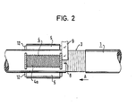
- the feed roller 4 as can be seen more clearly from FIG. 2, is provided on the outer circumference with an external thread 4a. After the desired setting edge has been inserted, the feed roller 4 is locked by means of the rotary knob 19 and adjustment of the thread 20. As a result, when the rotary peeling device is turned onto the wire 1, a feed is generated and the wire 1 is peeled off towards the cable end in the peeling direction A to the depth 3 shown schematically in FIG. 2.
- the chip removed from the peeling knife 8 is discharged to the outside via a chip discharge channel, which expediently runs as a bore from the peeling knife 8 within the knife guide 9, the knurled nut 10 and the knife holder 11. The chip then emerges upwards through the hole in the knife holder 11.
- the depth of cut of the peeling knife 8 is continuously adjusted by adjusting the knurled nut 10 and a self-locking thread on the knife holder 11.
Landscapes
- Removal Of Insulation Or Armoring From Wires Or Cables (AREA)
Applications Claiming Priority (2)
| Application Number | Priority Date | Filing Date | Title |
|---|---|---|---|
| DE3308197 | 1983-03-08 | ||
| DE19833308197 DE3308197C2 (de) | 1983-03-08 | 1983-03-08 | Rundschälgerät für kunststoffisolierte elektrische Kabel bzw. Adern |
Publications (2)
| Publication Number | Publication Date |
|---|---|
| EP0121680A2 true EP0121680A2 (fr) | 1984-10-17 |
| EP0121680A3 EP0121680A3 (fr) | 1985-11-13 |
Family
ID=6192857
Family Applications (1)
| Application Number | Title | Priority Date | Filing Date |
|---|---|---|---|
| EP84101336A Withdrawn EP0121680A3 (fr) | 1983-03-08 | 1984-02-09 | Dispositif de taille circonférentielle pour câbles ou âmes électriques isolés en matière synthétique |
Country Status (3)
| Country | Link |
|---|---|
| EP (1) | EP0121680A3 (fr) |
| DE (1) | DE3308197C2 (fr) |
| DK (1) | DK99484A (fr) |
Cited By (3)
| Publication number | Priority date | Publication date | Assignee | Title |
|---|---|---|---|---|
| US6311600B1 (en) | 1999-10-20 | 2001-11-06 | Hong Kong Polytechnic University | Electric power cable sheath cutter |
| CN103579959A (zh) * | 2013-10-15 | 2014-02-12 | 国家电网公司 | 一种便携式电缆护套层剥切器 |
| CN104037671A (zh) * | 2014-04-30 | 2014-09-10 | 国网河南省电力公司焦作供电公司 | 110kV电缆主绝缘电动成型切刀 |
Family Cites Families (8)
| Publication number | Priority date | Publication date | Assignee | Title |
|---|---|---|---|---|
| DE152887C (fr) * | ||||
| US3218709A (en) * | 1963-04-04 | 1965-11-23 | Union Carbide Corp | Cable sheath cutting device |
| FR2173819B1 (fr) * | 1972-03-03 | 1975-10-24 | Pinchon Raymond | |
| DE2210910A1 (de) * | 1972-03-07 | 1973-09-27 | Kabel Metallwerke Ghh | Vorrichtung zum abisolieren der leiterenden von starkstromkabeln |
| GB1458366A (en) * | 1973-04-26 | 1976-12-15 | Bieganski Z | Tools for cutting |
| DE7613740U1 (de) * | 1976-04-28 | 1976-10-28 | Schleifer, Werner, 4590 Cloppenburg | Konusschneider |
| DE3214479C2 (de) * | 1981-07-22 | 1986-05-15 | Siemens AG, 1000 Berlin und 8000 München | Handgerät zum Abschälen der äußeren Mantelschicht elektrischer Leitungen und elektrischer Kabel |
| DE8211568U1 (de) * | 1982-04-22 | 1982-09-16 | Hadres Werkzeugfabrik Bodo Heinrich Habel, 6800 Mannheim | Vorrichtung zum Schälen von Kabeln |
-
1983
- 1983-03-08 DE DE19833308197 patent/DE3308197C2/de not_active Expired
-
1984
- 1984-02-09 EP EP84101336A patent/EP0121680A3/fr not_active Withdrawn
- 1984-02-24 DK DK99484A patent/DK99484A/da not_active Application Discontinuation
Cited By (4)
| Publication number | Priority date | Publication date | Assignee | Title |
|---|---|---|---|---|
| US6311600B1 (en) | 1999-10-20 | 2001-11-06 | Hong Kong Polytechnic University | Electric power cable sheath cutter |
| CN103579959A (zh) * | 2013-10-15 | 2014-02-12 | 国家电网公司 | 一种便携式电缆护套层剥切器 |
| CN103579959B (zh) * | 2013-10-15 | 2016-02-10 | 国家电网公司 | 一种便携式电缆护套层剥切器 |
| CN104037671A (zh) * | 2014-04-30 | 2014-09-10 | 国网河南省电力公司焦作供电公司 | 110kV电缆主绝缘电动成型切刀 |
Also Published As
| Publication number | Publication date |
|---|---|
| DE3308197C2 (de) | 1988-06-16 |
| EP0121680A3 (fr) | 1985-11-13 |
| DE3308197A1 (de) | 1984-09-20 |
| DK99484A (da) | 1984-09-09 |
| DK99484D0 (da) | 1984-02-24 |
Similar Documents
| Publication | Publication Date | Title |
|---|---|---|
| EP0070554B1 (fr) | Outil à main pour tailler la couche de la gaine externe de lignes électriques et de câbles électriques | |
| DE202014101596U1 (de) | Vorrichtung zum Abisolieren von Koaxialkabeln | |
| DE102007019386A1 (de) | Abmantelwerkzeug | |
| DE2232714B2 (de) | Gerät zum Abisolieren in einem mehradrigen elektrischen Flachkabel zusammenhängender isolierter Adern | |
| DE1765588A1 (de) | Vorrichtung zum Abschneiden und gleichzeitigen gestuften Abisolieren von Koaxialkabeln | |
| EP0121680A2 (fr) | Dispositif de taille circonférentielle pour câbles ou âmes électriques isolés en matière synthétique | |
| EP1086513B1 (fr) | Borne de connexion | |
| DE1954415C3 (de) | Vorrichtung zur Vorbereitung eines Koaxialkabelendes für die Anbringung eines Koaxialkabelverbinders | |
| DE4327356A1 (de) | Vorrichtung zum Abisolieren von Litzenleitern | |
| DE3784892T2 (de) | Elektrisches Kabelzubereitungswerkzeug. | |
| EP0222112B1 (fr) | Dispositif de dénudage de câbles | |
| EP0216020A2 (fr) | Dispositif pour déduire un bout d'un câble coaxial | |
| CH607389A5 (en) | Cable insulation stripper with three jaws | |
| EP0841716B1 (fr) | Méthode et dispositif permettant d'obtenir une connexion électrique entre un appareil d'installation et un conducteur électrique entouré d'une isolation | |
| DE4205066C2 (de) | Werkzeug zum Schälen eines Auslaufkonus an Kabeln, insb. Hochspannungskabeln | |
| EP3695944B1 (fr) | Procédé et dispositif de division des objets en forme de plaque de matériaux friables | |
| DE69208235T2 (de) | Herstellungsverfahren zum Schneiden und Vorentmanteln von Kabeln und Drahtleitern und Apparat zur Durchführung des Verfahrens | |
| DE4036011C2 (de) | Vorrichtung zum Durchtrennen einer metallischen Abschirmung | |
| AT524372B1 (de) | Vorrichtung zum abmanteln eines geschirmten kabels | |
| DE102022204819B3 (de) | Vorrichtung und Verfahren zum Abisolieren eines Flachdrahtes bei der Herstellung von Stator- und Rotorwicklungen | |
| DE19515880C1 (de) | Vorrichtung zum Entfernen des Mantels von ummantelten Leitern oder Kabeln | |
| DE3125969C2 (de) | Verfahren zum Abisolieren der Enden eines Flachkabels | |
| DE4028491C2 (fr) | ||
| DE3248683C2 (fr) | ||
| DE2044036A1 (de) | Vorrichtung zur Schaffung einer Öffnung in einem Überzug eines mit Metall überzöge nen Kabels |
Legal Events
| Date | Code | Title | Description |
|---|---|---|---|
| PUAI | Public reference made under article 153(3) epc to a published international application that has entered the european phase |
Free format text: ORIGINAL CODE: 0009012 |
|
| AK | Designated contracting states |
Designated state(s): AT CH LI NL SE |
|
| PUAL | Search report despatched |
Free format text: ORIGINAL CODE: 0009013 |
|
| AK | Designated contracting states |
Designated state(s): AT CH LI NL SE |
|
| 17P | Request for examination filed |
Effective date: 19851204 |
|
| 17Q | First examination report despatched |
Effective date: 19861029 |
|
| STAA | Information on the status of an ep patent application or granted ep patent |
Free format text: STATUS: THE APPLICATION IS DEEMED TO BE WITHDRAWN |
|
| 18D | Application deemed to be withdrawn |
Effective date: 19880830 |
|
| RIN1 | Information on inventor provided before grant (corrected) |
Inventor name: BECKER, FRANK, DIPL.-ING. Inventor name: BLANKENBURG, BERND, DR. ING. |