EP0121714A2 - Système pour la correction automatique de l'étalonnage des longueurs d'ondes - Google Patents
Système pour la correction automatique de l'étalonnage des longueurs d'ondes Download PDFInfo
- Publication number
- EP0121714A2 EP0121714A2 EP84101990A EP84101990A EP0121714A2 EP 0121714 A2 EP0121714 A2 EP 0121714A2 EP 84101990 A EP84101990 A EP 84101990A EP 84101990 A EP84101990 A EP 84101990A EP 0121714 A2 EP0121714 A2 EP 0121714A2
- Authority
- EP
- European Patent Office
- Prior art keywords
- wavelength scale
- shift
- diffraction grating
- image
- undiffracted
- Prior art date
- Legal status (The legal status is an assumption and is not a legal conclusion. Google has not performed a legal analysis and makes no representation as to the accuracy of the status listed.)
- Withdrawn
Links
Images

Classifications
-
- G—PHYSICS
- G01—MEASURING; TESTING
- G01J—MEASUREMENT OF INTENSITY, VELOCITY, SPECTRAL CONTENT, POLARISATION, PHASE OR PULSE CHARACTERISTICS OF INFRARED, VISIBLE OR ULTRAVIOLET LIGHT; COLORIMETRY; RADIATION PYROMETRY
- G01J3/00—Spectrometry; Spectrophotometry; Monochromators; Measuring colours
- G01J3/28—Investigating the spectrum
- G01J2003/2866—Markers; Calibrating of scan
-
- G—PHYSICS
- G01—MEASURING; TESTING
- G01J—MEASUREMENT OF INTENSITY, VELOCITY, SPECTRAL CONTENT, POLARISATION, PHASE OR PULSE CHARACTERISTICS OF INFRARED, VISIBLE OR ULTRAVIOLET LIGHT; COLORIMETRY; RADIATION PYROMETRY
- G01J3/00—Spectrometry; Spectrophotometry; Monochromators; Measuring colours
- G01J3/12—Generating the spectrum; Monochromators
- G01J3/18—Generating the spectrum; Monochromators using diffraction elements, e.g. grating
Definitions
- This invention relates to optical instruments, and more particularly to systems in spectrometers and monochromators for maintaining them in correct wavelength calibration over long periods of time.
- a spectrometer is an optical instrument used to measure the spectral content of light. In making a spectral measurement the spectrometer first divides or separates the light into its component wavelengths, and then measures the intensity of the light at one or more wavelengths, or narrow wavelength bands, simultaneously or sequentially.
- a monochromator is a modified spectrometer which isolates a single wavelength, or narrow wavelength band, at a time for measurement.
- optical instruments such as spectrometers or monochromators use a diffraction grating or a prism to separate light into its component wavelengths.
- a diffraction grating When a diffraction grating is used, light incident upon the grating is separated into its component wavelengths by the process of diffraction, i.e., the diffraction grating deflects the various wavelengths comprising the light through different angles. The resulting angular separation of the wavelengths is then converted into spatial separation by a focusing mirror or lens to allow corresponding spatially separated photoelectric devices to measure the intensity of light at the various wavelengths.
- Wavelength errors in such instruments are normally corrected by adjusting the instrument while it is illuminated with a light source having a known narrow spectral "line" (e.g., lasers and certain gas discharge lamps). Since the wavelength of the emitted line is known, the spectrometer or monochromator can be aligned by mechanically adjusting its optical and/or mechanical structures so that the line follows the correct path through the optical system. Such an adjustment may require a shift in the wavelength scale itself.
- a light source having a known narrow spectral "line” e.g., lasers and certain gas discharge lamps.
- a primary object of the present invention is to provide a system that can automatically maintain spectrometers and monochromators in proper calibration.
- Another object of the present invention is to provide a system that can automatically maintain spectrometers and monochromators in proper calibration by mechanically adjusting an instrument's various mechanical and/or optical structures.
- a further object of the present invention is to provide a system that can automatically maintain spectrometers and monochromators in correct calibration by relabeling an instrument's wavelength scale outputs in response to shifts and/or deformations in the instrument's various optical and/or mechanical structures.
- a system for maintaining the wavelenth scale calibration of a spectrometer or monochromator utilizing a diffraction grating to disperse light entering the spectrometer or monochromator into its component wavelengths characterized in that it comprises means for measuring the magnitude and direction of shift occurring in the position of an undiffracted image of the entering light's entry point emanating from the diffraction grating; and means for correcting the calibration of the wavelength scale utilizing said measured shift.
- the present invention is directed towards a system and a method for keeping the wavelength scales of diffraction grating based spectrometers and monochromators correctly calibrated.
- One or more photodetectors measure the direction and degree of error in the output of an instrument's wavelength scale due to mechanical misalignment by measuring the direction and degree of shift in the position of undiffracted light that is reflected or transmitted by the instrument's diffraction grating.
- the instrument can be realigned either by automatically adjusting its various optical and/or mechanical structures accordingly, or by relabeling the wavelength values of its wavelength scale outputs in response to the shift in position of the undiffracted light.
- a diffraction grating is used to diffract light into its component wavelengths, yet it does not diffract all of the light incident upon it.
- a portion of the light is diffracted so as to be reflected at various angles, depending upon wavelength, while a portion of the light is undiffracted so as to be reflected from the grating like from a mirror.
- This undiffracted, reflected light retains an approximately fixed angular relationship with respect to the diffracted light.
- the angle at which the diffracted light is reflected changes for whatever reason, the angle at which the undiffracted light is reflected will change by a corresponding amount.
- deformations effects such as thermal variations and long term “creep” can cause shifts, deformations and the like (hereinafter called deformations) in the various optical and mechanical structures of instruments such as spectrometers and monochromators, which can result in output errors in their wavelength scales.
- Such deformations can occur either after or before or at an instrument's diffraction grating.
- the angular relationship between the undiffracted light beam and the diffracetd light beams emanating from the grating remains constant.
- This constant angular relationship between the two kinds of beams can be used to correct wavelength scale errors by correcting misalignments in the position of the undiffracted light beams. Since the undiffracted light beam is always reflected as from a mirror, the degree of shift in its position can easily be measured. Once this information is known, it can be used to correct any misalignment in the position of the instrument's diffracted beams because degree and direction of their misalignment will always be the same as the degree and direction of misalignment of the undiffracted beam.
- Fig. 1 shows the angular relationship between incident 11, undiffracted 12 and diffracted 13 light beams for a concave reflection grating 14.
- the angle of incidence of the incident beam 11 is arbitrarily shown to be ⁇ .
- the undiffracted beam 12 is reflected at the same angle ⁇ on the other side of a normal 15.
- the diffracted beam 13 is reflected at an angle B which corresponds to some arbitrary wavelength ⁇ .
- the angular relationship among the various beams is as follows:
- Equation (5) indicates that the angular correction ⁇ B to be applied to the diffracted light is proportional to the angular error in ⁇ .
- the proportionality constant depends on ⁇ and B , both of which are known. Thus, if the angular error in the undiffracted light ⁇ can be measured, it can be used to calculate via equation (5) the error A in the wavelength scale. Here, however, the proportionality constant is not necessarily equal to unity. Since B is wavelength dependent, the proportionality constant cosoc/cosB is also wavelength dependent.
- correction for errors is a non-linear function of wavelength when deformations occur before or at the grating so as to cause errors to occur in ⁇ , while correction is the same for all wavelengths when deformations occur after the grating.
- the spatial error in the wavelength scale is equal to the spatial error in the location of the undiffracted image.
- wavelength scale Spatial coordinates of the wavelength scale bear a one-to- one correspondence to wavelength values.
- the wavelength scale is linear, so that the spatial coordinates in the wavelength scale can be converted to wavelength units by multiplying by a known constant.
- conversion to wavelength can be achieved through the use of an equation, or via a look-up table.
- the appro- p riate relationship can be determined theoretically, or measuring the physical position of the diffracted image as a function of input wavelength.
- the angle cc can be controlled by adjusting the orientation of the diffraction grating 14 with respect to the entrance slit of the optical instrument, while B can be controlled by changing the grating constant (i.e., the number of grooves per millimeter) of the grating.
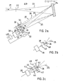
- Fig. 2A shows the optical diagram of a spectrometer utilizing a reflection grating and a block diagram of one embodiment of the invention for correcting errors in the spectrometer's wavelength scale.
- the light 21 to be analyzed by the spectrometer is incident upon an entrance slit 22.
- a portion 23 of light 21 passes through the entrance slit, after which it diverges until it impinges on a concave diffraction grating 24.
- the majority of it is diffracted so as to emanate from the grating at various angles; however, a portion 25 of the light is reflected from grating 24 as from a mirror.
- Reflected or undiffracted light 25 depicted by solid lines, is reflected from the diffraction grating 24 at an angle of reflection which is equal to its angle of incidence upon grating 24.
- This undiffracted light is focused by the grating at a point 26 which represents a direct image, or zero order diffracted image of entrance slit 22. This image is composed of a broad range of wavelengths.
- Diffracted light 26 is reflected from the diffraction grating 24 at various angles, depending upon the wavelength of the diffracted light.
- Figure 2A shows light beams for two arbitrary wavelengths, ⁇ 1 and ⁇ 2 , depicted by dashed lines 28 and dotted lines 29, respectively. These diffracted rays are focused by the diffraction grating at points 30 and 31, respectively, which represent images of entrance slit 22 at wavelengths ⁇ 1 and X 2, respectively.
- the spectrometer has two photodetectors 32 and 33 placed at points 30 and 31, respectively, for sensing the intensity of light at wavelengths ⁇ 1 and X 2, respectively. Where light intensity is to be sensed at a multiplicity of wavelengths, an array of photodetectors, or a vidicon detector or the like can be used.
- the spatial displacement of image 26 is measured.
- the spatial displacement of image 26 is measured.
- the embodiment of the invention shown in Fig. 2A uses a pair of photodetectors 34 and 35 straddling image point 26, such that it falls midway between the two detectors, causing an equal amount of undiffracted light to fall on both photodetectors when the instrument is properly aligned.
- the outputs of these photodetectors are, in turn, connected to amplifiers 36 and 37 which, in turn, are connected to a microcomputer 38 using to interpret this information.
- the two photodetectors 34 and 35 will not receive an equal amount of light.
- the ratio of the output of detector 34 to the output of detector 35 will increase as the zero order image 26 moves toward detector 34, and will decrease as it moves away.
- the system can be initially calibrated so that there is a unique relationship between the ratio of the photodetector outputs and the correct position of image 26.
- Changes in this initial detector output ratio represent shifts in the spatial position of image 26, and as noted previously, are used to correct errors in the wavelength scale of the spectrometer.
- the spatial error in the wavelength scale is set equal to the measured spatial error in the position of the undiffracted image 26.
- the corresponding wavelength error is found by converting spatial error into wavelength error, via a known linear or non-linear equation or from a look-up table.
- sensing of the position of the zero order image 26 can be done by a single photodetector 39 connected to microcomputer 38 through a single amplifier 40.
- the photodetector 39 is positioned such that approximately half of the photodetector is illuminated by image 26 when the optical system is properly aligned. If a misalignment occurs, the signal generated in the single photodetector 39 will increase if the image moves toward the center of the photodetector, or decrease if the image moves away from the center of the photodetector.
- sensing of the position of the zero order image 26 can be done by a series of three (or more) photodetectors 41, 42 and 43 disposed in a straight line and connected to microcomputer 38 through amplifiers 44, 45 and 46, respectively.
- the detectors should be closely spaced, and of such a size that light from the image 26 is incident upon all detectors.
- ratios of detector outputs such as the ratios of the outputs of detectors 42 and 43 to the output of detector 42, can be used to sense shifts in the position of image 26.
- photodetectors 34 and 35 are mechanically mounted on the same plate 48 used to mount photodetectors 32 and 33. This arrangement is used to achieve a constant positional relationship between the two sets of photodetectors.
- circuit 49 is also provided with additional outputs for driving other mechanical positioning apparatus to position the other optical and mechanical structures of the spectrometer, if necessary, for error correction.
- the present invention can also be used with spectrometers having optical configurations other than that shown in Fig. 2A.
- a spectrometer could use a plane diffraction grating which would require additional optical elements (e.g., lenses or concave mirrors) between entrance slit 22 and diffraction grating 24 and the diffraction grating and photodetectors 32 and 33 to achieve the necessary focusing requirement by the instrument.
- additional optical elements e.g., lenses or concave mirrors
- the use of these additional elements increases the likelihood of a mechanical misalignment that will affect the accuracy of the spectrometer's wavelength scale.
- an optical arrangement which includes a concave diffraction grating is used. This arrangement also allows the diffracted and undiffracted images to be positioned close to each other for optimum system performance.
- Fig. 3 shows a block diagram of the present invention being used with a typical monochromator.
- light 51 which is incident upon an entrance slit 52 thereof, diverges to a concave diffraction grating 53 within the monochromator.
- Grating 53 focuses undiffracted light 54, depicted by solid lines, to a point 55, and diffracted light 56, depicted by dashed lines, to a point 57.
- Point 55 which is the zero order image, is located between adjacent photodetectors 34 and 35 which, as noted previously, are connected to microcomputer 38 through amplifiers 36 and 37, respectively.
- the diffracted image 57 passes through an exit slit 58.
- the wavelength of this diffracted image is determined by the angular orientation of grating 53.
- rotation of the grating about an axis 59 shown normal to the surface of the diagram, will result in angular rotations of the undiffracted and diffracted beams 54 and 56, and variation of the wavelength of the light beam present at exit slit 58.
- the calibration wavelength When the angular position of grating 53 is such that the undiffracted image 55 is properly centered between detectors 34 and 35, and their electrical output signals are equal, there is only one wavelength, called the calibration wavelength, that should appear at exit slit 58.
- This wavelength can be determined in a one-time wavelength calibration of the monochromator. From that time on, the calibration wavelength can be expected to appear at the exit slit 58 whenever the zero order image 55 is properly centered. If the grating 53 is rotated on its axis to the angle at which the calibration wavelength is expected to appear at exit slit 58, and the zero order image 55 is not properly centered as determined from the outputs of detectors 34 and 35, then an error in the wavelength scale has occurred.
- microcomputer 38 uses this information to realign the monochromator. If reassignment of the wavelength of the diffracted light is used, it is performed in the same manner as for spectrometers. If mechanical correction is used, it is easily achieved by microcomputer 38 rotating grating 53 about axis 59 through a typical electromechanical drive circuit 60 which is mechanically coupled to grating 53.
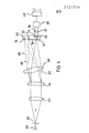
- Fig. 4 shows the present invention as it is used with a spectrometer utilizing a transmission diffraction grating.
- incident light 61 passes through an entrance slit 62 and diverges to a lens 63, which collimates the light and directs it toward a transmission grating 64.
- Undiffracted light 65 depicted by solid lines, passes straight through the grating 64, after which it is focused by a lens 66 to a point 67. Point 67 is located midway between adjacent photodetectors 34 and 35.
- Diffracted light at wavelengths ⁇ 1 and ⁇ 2 depicted by dashed lines 68 and dotted lines 69, respectively, are imaged to points 70 and 71. Beams 68 and 69 are sensed by photodetectors 32 and 33. Compensation of wavelength errors is achieved in the identical fashion as described for a spectrometer using a reflection diffraction grating.
Landscapes
- Physics & Mathematics (AREA)
- Spectroscopy & Molecular Physics (AREA)
- General Physics & Mathematics (AREA)
- Spectrometry And Color Measurement (AREA)
- Investigating Or Analysing Materials By Optical Means (AREA)
Applications Claiming Priority (2)
| Application Number | Priority Date | Filing Date | Title |
|---|---|---|---|
| US47165983A | 1983-03-03 | 1983-03-03 | |
| US471659 | 1983-03-03 |
Publications (2)
| Publication Number | Publication Date |
|---|---|
| EP0121714A2 true EP0121714A2 (fr) | 1984-10-17 |
| EP0121714A3 EP0121714A3 (fr) | 1986-05-07 |
Family
ID=23872514
Family Applications (1)
| Application Number | Title | Priority Date | Filing Date |
|---|---|---|---|
| EP84101990A Withdrawn EP0121714A3 (fr) | 1983-03-03 | 1984-02-25 | Système pour la correction automatique de l'étalonnage des longueurs d'ondes |
Country Status (2)
| Country | Link |
|---|---|
| EP (1) | EP0121714A3 (fr) |
| JP (1) | JPS59164924A (fr) |
Cited By (7)
| Publication number | Priority date | Publication date | Assignee | Title |
|---|---|---|---|---|
| EP0140661A3 (fr) * | 1983-11-01 | 1987-04-15 | Westinghouse Electric Corporation | Dispositif d'analyse d'un faisceau lumineux |
| US4779216A (en) * | 1986-03-07 | 1988-10-18 | The Perkin-Elmer Corporation | System for calibrating a monochromator |
| WO1992005412A1 (fr) * | 1990-09-14 | 1992-04-02 | Oplatek Oy | Realisation d'un calibrage spectrometrique de la lumiere |
| EP1634043A1 (fr) * | 2003-06-02 | 2006-03-15 | Sensovation AG | Appareil et procedes de mesure photoelectrique |
| WO2013135281A1 (fr) * | 2012-03-14 | 2013-09-19 | Foss Analytical Ab | Spectromètre à dispersion |
| CN105938013A (zh) * | 2016-04-20 | 2016-09-14 | 杭州远方光电信息股份有限公司 | 一种光谱仪及其校正方法 |
| CN116625959A (zh) * | 2023-07-17 | 2023-08-22 | 北京卓立汉光仪器有限公司 | 光栅光谱仪的波长校准方法 |
Families Citing this family (2)
| Publication number | Priority date | Publication date | Assignee | Title |
|---|---|---|---|---|
| JPH0663866B2 (ja) * | 1984-10-08 | 1994-08-22 | 日本電気株式会社 | 波長検出装置 |
| JPS62226024A (ja) * | 1986-03-28 | 1987-10-05 | Matsushita Electric Ind Co Ltd | 分光器 |
Family Cites Families (6)
| Publication number | Priority date | Publication date | Assignee | Title |
|---|---|---|---|---|
| GB869257A (en) * | 1957-10-30 | 1961-05-31 | Baird Atomic Inc | Spectroscopic apparatus |
| GB1005824A (en) * | 1962-10-22 | 1965-09-29 | Nat Res Dev | Spectrometers employing diffraction gratings |
| US3762821A (en) * | 1971-01-25 | 1973-10-02 | Bell Telephone Labor Inc | Lens assembly |
| US3846024A (en) * | 1972-06-12 | 1974-11-05 | Baird Atomic Inc | Optical alignment system for optical spectrometers |
| JPS5919291B2 (ja) * | 1976-01-07 | 1984-05-04 | 株式会社日立製作所 | 分光器自動波長校正装置 |
| JPS5770415A (en) * | 1980-10-22 | 1982-04-30 | Hitachi Ltd | Initial setting device for wavelength of spectrophotometer |
-
1984
- 1984-02-07 JP JP2150084A patent/JPS59164924A/ja active Pending
- 1984-02-25 EP EP84101990A patent/EP0121714A3/fr not_active Withdrawn
Cited By (12)
| Publication number | Priority date | Publication date | Assignee | Title |
|---|---|---|---|---|
| EP0140661A3 (fr) * | 1983-11-01 | 1987-04-15 | Westinghouse Electric Corporation | Dispositif d'analyse d'un faisceau lumineux |
| US4779216A (en) * | 1986-03-07 | 1988-10-18 | The Perkin-Elmer Corporation | System for calibrating a monochromator |
| WO1992005412A1 (fr) * | 1990-09-14 | 1992-04-02 | Oplatek Oy | Realisation d'un calibrage spectrometrique de la lumiere |
| EP1634043A1 (fr) * | 2003-06-02 | 2006-03-15 | Sensovation AG | Appareil et procedes de mesure photoelectrique |
| WO2013135281A1 (fr) * | 2012-03-14 | 2013-09-19 | Foss Analytical Ab | Spectromètre à dispersion |
| CN104160252A (zh) * | 2012-03-14 | 2014-11-19 | 福斯分析有限公司 | 色散光谱仪 |
| CN104160252B (zh) * | 2012-03-14 | 2016-03-16 | 福斯分析有限公司 | 色散光谱仪 |
| AU2012372923B2 (en) * | 2012-03-14 | 2016-04-14 | Foss Analytical Ab | Dispersion spectrometer |
| CN105938013A (zh) * | 2016-04-20 | 2016-09-14 | 杭州远方光电信息股份有限公司 | 一种光谱仪及其校正方法 |
| CN105938013B (zh) * | 2016-04-20 | 2019-12-17 | 杭州远方光电信息股份有限公司 | 一种光谱仪及其校正方法 |
| CN116625959A (zh) * | 2023-07-17 | 2023-08-22 | 北京卓立汉光仪器有限公司 | 光栅光谱仪的波长校准方法 |
| CN116625959B (zh) * | 2023-07-17 | 2023-11-10 | 北京卓立汉光仪器有限公司 | 光栅光谱仪的波长校准方法 |
Also Published As
| Publication number | Publication date |
|---|---|
| JPS59164924A (ja) | 1984-09-18 |
| EP0121714A3 (fr) | 1986-05-07 |
Similar Documents
| Publication | Publication Date | Title |
|---|---|---|
| US5790242A (en) | Chromatic optical ranging sensor | |
| US5543916A (en) | Interferometer with alignment assembly and with processor for linearizing fringes for determining the wavelength of laser light | |
| US4983039A (en) | Spectrometer | |
| US5581350A (en) | Method and system for calibrating an ellipsometer | |
| EP1026487B1 (fr) | Spectromètre à étalon avec passage double | |
| US5349439A (en) | Opto-electronic measuring device with optical air wedge spectral analysis arrangement | |
| US4936684A (en) | Spectrometer with photodetector array detecting uniform bandwidth intervals | |
| US4568187A (en) | Concave grating spectrometer | |
| US3861801A (en) | Device for sampling laser beams | |
| US5592291A (en) | Spectrophotometer | |
| EP0315663B1 (fr) | Detecteur compact du front d'ondes d'ondes entretenues | |
| EP1120637A2 (fr) | Procédé et appareil de calibration d'un monochromateur à réseau | |
| WO2000079229A1 (fr) | Dispositifs optiques a miroirs toroidaux pour effectuer des mesures de facteur de reflexion | |
| WO1998054548A1 (fr) | Procedes et appareil de positionnement | |
| US5973780A (en) | Echelle spectroscope | |
| EP0247067B1 (fr) | Dispositif a circuits integres pour la determination de la pente d'un front d'ondes | |
| JPS59164924A (ja) | 較正波長の自動補正システム | |
| US6597451B1 (en) | Spectrometry measuring apparatus | |
| US5066129A (en) | Optical linear encoder with light quantity calabration | |
| US5592285A (en) | Optical source position and direction sensor | |
| US4605314A (en) | Spectral discrimination pyrometer | |
| JPS6038644B2 (ja) | 分光光度計 | |
| JP2002522782A (ja) | 発光ビームの波長を測定するための装置 | |
| US5276499A (en) | Spectrophotometer | |
| US6885447B2 (en) | Spectrometer and optical spectrum analyzer |
Legal Events
| Date | Code | Title | Description |
|---|---|---|---|
| PUAI | Public reference made under article 153(3) epc to a published international application that has entered the european phase |
Free format text: ORIGINAL CODE: 0009012 |
|
| AK | Designated contracting states |
Designated state(s): CH DE FR GB LI |
|
| PUAL | Search report despatched |
Free format text: ORIGINAL CODE: 0009013 |
|
| AK | Designated contracting states |
Kind code of ref document: A3 Designated state(s): CH DE FR GB LI |
|
| STAA | Information on the status of an ep patent application or granted ep patent |
Free format text: STATUS: THE APPLICATION IS DEEMED TO BE WITHDRAWN |
|
| 18D | Application deemed to be withdrawn |
Effective date: 19860829 |
|
| RIN1 | Information on inventor provided before grant (corrected) |
Inventor name: KISHNER, STANLEY J. |