EP0121734A1 - Vorrichtung zum Messen der Drehungen einer Durchflusszählerturbine - Google Patents
Vorrichtung zum Messen der Drehungen einer Durchflusszählerturbine Download PDFInfo
- Publication number
- EP0121734A1 EP0121734A1 EP84102204A EP84102204A EP0121734A1 EP 0121734 A1 EP0121734 A1 EP 0121734A1 EP 84102204 A EP84102204 A EP 84102204A EP 84102204 A EP84102204 A EP 84102204A EP 0121734 A1 EP0121734 A1 EP 0121734A1
- Authority
- EP
- European Patent Office
- Prior art keywords
- turbine
- receiver
- transmitter
- electromagnetic flux
- rotation
- Prior art date
- Legal status (The legal status is an assumption and is not a legal conclusion. Google has not performed a legal analysis and makes no representation as to the accuracy of the status listed.)
- Granted
Links
- 230000004907 flux Effects 0.000 claims abstract description 31
- 239000012530 fluid Substances 0.000 claims abstract description 22
- 238000001514 detection method Methods 0.000 claims description 12
- 230000005540 biological transmission Effects 0.000 claims description 6
- 230000035699 permeability Effects 0.000 claims description 4
- 229910000859 α-Fe Inorganic materials 0.000 claims description 4
- 230000003321 amplification Effects 0.000 claims description 2
- 238000003199 nucleic acid amplification method Methods 0.000 claims description 2
- 230000015572 biosynthetic process Effects 0.000 claims 1
- 230000000737 periodic effect Effects 0.000 claims 1
- XLYOFNOQVPJJNP-UHFFFAOYSA-N water Substances O XLYOFNOQVPJJNP-UHFFFAOYSA-N 0.000 description 24
- XEEYBQQBJWHFJM-UHFFFAOYSA-N Iron Chemical compound [Fe] XEEYBQQBJWHFJM-UHFFFAOYSA-N 0.000 description 6
- 238000005259 measurement Methods 0.000 description 5
- 239000002245 particle Substances 0.000 description 4
- 230000008859 change Effects 0.000 description 3
- 229910052742 iron Inorganic materials 0.000 description 3
- 239000007789 gas Substances 0.000 description 2
- 239000000696 magnetic material Substances 0.000 description 2
- 239000000463 material Substances 0.000 description 2
- 230000007246 mechanism Effects 0.000 description 2
- 230000004048 modification Effects 0.000 description 2
- 238000012986 modification Methods 0.000 description 2
- 230000010355 oscillation Effects 0.000 description 2
- 230000000750 progressive effect Effects 0.000 description 2
- 239000007787 solid Substances 0.000 description 2
- VYZAMTAEIAYCRO-UHFFFAOYSA-N Chromium Chemical compound [Cr] VYZAMTAEIAYCRO-UHFFFAOYSA-N 0.000 description 1
- CWYNVVGOOAEACU-UHFFFAOYSA-N Fe2+ Chemical compound [Fe+2] CWYNVVGOOAEACU-UHFFFAOYSA-N 0.000 description 1
- 230000032683 aging Effects 0.000 description 1
- XAGFODPZIPBFFR-UHFFFAOYSA-N aluminium Chemical compound [Al] XAGFODPZIPBFFR-UHFFFAOYSA-N 0.000 description 1
- 229910052782 aluminium Inorganic materials 0.000 description 1
- 230000000903 blocking effect Effects 0.000 description 1
- 229910052804 chromium Inorganic materials 0.000 description 1
- 239000011651 chromium Substances 0.000 description 1
- 239000011248 coating agent Substances 0.000 description 1
- 238000000576 coating method Methods 0.000 description 1
- 239000004020 conductor Substances 0.000 description 1
- 230000008878 coupling Effects 0.000 description 1
- 238000010168 coupling process Methods 0.000 description 1
- 238000005859 coupling reaction Methods 0.000 description 1
- 238000006073 displacement reaction Methods 0.000 description 1
- -1 for example Substances 0.000 description 1
- 239000007788 liquid Substances 0.000 description 1
- 230000005415 magnetization Effects 0.000 description 1
- 230000009347 mechanical transmission Effects 0.000 description 1
- 238000000034 method Methods 0.000 description 1
- 230000007935 neutral effect Effects 0.000 description 1
- 238000007493 shaping process Methods 0.000 description 1
Images


Classifications
-
- G—PHYSICS
- G01—MEASURING; TESTING
- G01F—MEASURING VOLUME, VOLUME FLOW, MASS FLOW OR LIQUID LEVEL; METERING BY VOLUME
- G01F1/00—Measuring the volume flow or mass flow of fluid or fluent solid material wherein the fluid passes through a meter in a continuous flow
- G01F1/05—Measuring the volume flow or mass flow of fluid or fluent solid material wherein the fluid passes through a meter in a continuous flow by using mechanical effects
- G01F1/06—Measuring the volume flow or mass flow of fluid or fluent solid material wherein the fluid passes through a meter in a continuous flow by using mechanical effects using rotating vanes with tangential admission
- G01F1/075—Measuring the volume flow or mass flow of fluid or fluent solid material wherein the fluid passes through a meter in a continuous flow by using mechanical effects using rotating vanes with tangential admission with magnetic or electromagnetic coupling to the indicating device
Definitions
- the present invention relates to a device for measuring the rotation of a turbine of fluid flow meters, whether these fluids are liquids or gases.
- the present invention aims to solve the drawbacks of counting devices of the types known above and relates to a device for measuring the rotation of a turbine of fluid flow meters, in which a turbine is driven in rotation in a fluid circulation chamber to be counted.
- This device comprises at least one emitter of electromagnetic flux, at least one receiver of the electromagnetic flux emitted, a device for modulating the electromagnetic flux located between the emitter and the receiver and driven in rotation by the turbine, a device for supplying signals the transmitter, and a device for detecting the modulation of the electromagnetic flux arriving at the receiver, independent of the transmitter and its supply device, the transmitter and the receiver being optically independent of each other .
- an electromagnetic flux transmitter and receiver it is possible to make a counting device with a device for supplying electrical signals to the transmitter and with a device for detecting the signals received by the receiver having low current consumption and powered by low voltage electric batteries.
- the transmitter, the receiver, the transmitter supply device and the device for detecting the signals received by the receiver are placed outside the fluid circulation chamber directly above the plate. 5, however the transmitter supply device and the detection device can be placed at a certain distance from this chamber.
- the transmitter and receiver of flow not being bathed; by the fluid and using only a low power electromagnetic flux, they cannot be influenced by it nor attract iron-based particles contained in the fluid to be counted.
- the magnetic flux modulation device is neutral vis-à-vis the fluid to be measured, so that it can be contained in the fluid circulation chamber. The use of the modulation of an electromagnetic flux also makes it possible to measure low speeds of rotation of the turbine therefore low flow rates of the fluid.
- the device for modulating the electromagnetic flux is either a device with high electromagnetic permeability or, on the contrary, a device forming a screen for the electromagnetic flux.
- the present invention also resides in the fact that two transmitter-receiver pairs are used, angularly offset from one another, the counting of the rotation being carried out only when the detection of passage of the modulation device is carried out successively by both receptors.
- any untimely counting, due to oscillations of small amplitude of the modulation device, is not carried out, the counting taking place only if the displacement of the modulation device corresponds at least to the angular offset of the transmitter-receiver pairs, this offset being calculated so as to always be greater than the assumed maximum amplitude of the turbine oscillators around a fixed position.
- the device for measuring the rotation of a turbine is applied to a water meter to a body 1 comprising an inlet pipe 2 and a water outlet pipe 3 with the same axis XX and to a turbine or impeller 4, made of plastic, rotatably mounted, of axis YY, in the body 1 and driven in rotation by the water to be counted.
- the body 1 is closed at its upper part by a plate 5, of plastic material, forming a cover, screwed in a sealed manner in the body 1 and also serving as a bearing 6 for the turbine 4, so as to form a chamber C for circulation of water to count.
- the turbine or impeller 4 carries at its upper part two screens 7 and 8 formed by two diametrically opposite portions of a cylinder of axis YY and limited by generators, 7a and 7b for the screen 7 , 8a and 8b for screen 8, an angle A of approximately 45 ° from vertex YY being formed by the adjacent edges 7a-8b or 7b-8a, of each of screens 7 and 8.
- These screens are made of a material metallic such as aluminum or the same plastic as the turbine 4 but covered on at least one of their faces by a metallic coating such as, for example, chromium.
- the plate 5 has at its lower part, turbine side 4, a circular and deep groove 9 intended to allow the introduction of the screens 7 and 8 into the plate 5.
- This plate has at its upper part, on the side opposite to the chamber C water circulation to be counted, two radial recesses 10 and 11, in the form of rectangular parallelepipeds, located outside the groove circular 9 and forming between them an angle B of approximately 120 °, and a recess 12 in the form of a rectangular parallelepiped parallel to the axis XX, the ends of which are directed towards the two recesses 10 and 11.
- Each recess 10-11-12 contains an electrical coil respectively 13-14-15 each formed of a circular section bar 13a-14a-15a of magnetic material such as ferrite on which is wound over several turns an electric current conductor 13b-14b-15b .
- the electric coils 13 and 14 form receivers of electromagnetic flux emitted by the electric coil 15 or emitter of electromagnetic flux.
- the coil forming the transmitter is connected to a device for supplying electrical signals while the coils forming the receivers are connected to a detection device followed by a device for counting the modulation of the electromagnetic flux.
- These supply, detection and counting devices are located directly above the plate 5 or at a certain distance from the counter.
- FIG. 3 An example of these devices is shown in FIG. 3.
- one of the output wires 13b-14b-15b of each of the coils, respectively 13-14-15 is connected to a common point T acting as ground.
- the transmitter coil 15 is supplied by a supply device 16 delivering signals of very short duration in the form of sawtooth.
- Each of the coils or receivers 13-14 is connected to a device for shaping and amplification or amplifier 17, 18 respectively of the signal received by the corresponding receiver.
- the output of each of the amplifiers 17-18 delivering a determined signal is connected to an input of an electronic or bistable flip-flop 19 which changes state each time a signal is received from one of the amplifiers 17-18 and intended to deliver a signal when each of the amplifiers 17-18 has successively delivered an input signal.
- the bistable 19 is connected to an electronic counter 20 which counts the signals emitted by the bistable 19. Amplifiers, bistable and electronic counter form the detection device.
- one of the corner spaces A located between the screens 7 and 8 comes, for example between the transmitter 15 and the receiver 13, authorizing the reception of electromagnetic waves by this receiver which delivers via the amplifier 17 a signal to the bistable 19 ensuring its change of state, for example, the 'sending an electrical signal to the counter 20.
- the screen 8 prevents the transmission of electromagnetic waves to the receiver 14 which does not deliver any signal.
- the screen 7 comes to screen the receiver 13, the screen 8 always preventing the transmission of the waves to the receiver 14, no signal of change of state is sent to the bistable which therefore continues to send a signal electric at meter 20.
- the electromagnetic waves emitted by the transmitter 15 do not arrive simultaneously at the two receivers 13 and 14 therefore that the angles A are as small as possible and that the coils are not diametrically opposed. It is also necessary that this angle A is large enough to allow good transmission of the electromagnetic waves to the receivers 13-14.
- the angle B of the receivers being approximately 120 °
- the angle A of free space between the screens 7 and 8 must be between 15 and 90 ° approx.
- the frequency of the signals emitted by the transmitter must be as small as possible but sufficient to allow detection of the rotation of the turbine when it rotates at the highest speed corresponding to the maximum counting flow of the water meter.
- the frequency of the signals must be greater than the value of the relation: 3.14 / (3.14-A) T, the angle A being expressed in radians and T being the time expressed in seconds by the turbine to turn around when the maximum water flow passes through the water meter.
- this device makes it possible to ensure more reliable metering due to the absence of mechanical transmission liable to wear or of transmission by magnet capable of capturing ferrous particles contained in the water to be counted.
- This device is insensitive to fouling by water and makes it possible to measure low flow rates because it does not cause any braking of the turbine 4.
- the detection device can be located at a certain distance from the meter, therefore in more accessible locations to allow easy reading of the count.
- a power supply device 16 creating signals of very short duration (signal duration much less than cut-off time between two successive signals) makes it possible to require only a low consumption of electrical energy so that these devices can be powered by electric batteries or - " accumulators of electric current.
- a variant of the invention consists in replacing the two screens 7 and 8 by a single cylindrical screen provided with a single slot of angle identical to the angle A.
- the counting device 20 On each revolution of the turbine 4, only corresponds a single signal received by the counting device 20.
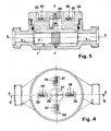
- FIG. 4 and 5 Another variant of the invention as shown in Figs. 4 and 5 consists in the use, in place of the screens 7 and 8, of two bars 27-28 made of magnetic material, with high magnetic permeability, such as ferrite, carried by the axis of rotation of the turbine 4 These bars are placed orthogonally and in different planes orthogonal to the axis YY of the turbine 4.
- the plate 25 closing the body 1 of the meter has four radial recesses 30-31-32-33 and regularly distributed around of the YY axis.
- Two transmitter coils 34-35 are located in two neighboring recesses 30-31 while two receiver coils 36-37 are located in two other recesses 32-33.
- the transmitting and receiving coils are identical to those previously described.
- the transmitter-receiver coils form two diametrically opposite transmitter-receiver pairs 34-36 and 35-37.
- the recesses 31-33 and 30-32 have different depths so that the coils 34-36 are in the same plane as the bar 28 and the coils 35-37 are in the same plane as that of the bar 27.
- the device supply and detection are of the same type as those described previously.
- the operation of the measuring device according to this variant differs from that described above only in that, instead of ensuring a stopping of the transmission of electromagnetic waves by screens as before, the alignment of the bars 27 - 28 with the associated transmitter-receiver pair respectively 35-37 and 34-36 ensures an increase in the electromagnetic waves received by the receivers.
- the device according to this alternative embodiment has the same advantages as above.
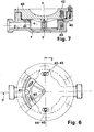
- FIGS. 6 and 7 Another alternative embodiment shown in FIGS. 6 and 7 consists in that the turbine 4 has at its upper part, on its periphery, a solid crown 40 provided with a notch 41 intended to come in front of two transmitter-receiver pairs of axis YY 42-43 and 44- 45 diametrically opposite and carried, on the one hand, by a plate 46 for upper closure of the body 1 and, on the other hand, by the body 1 itself.
- the operation of such a device equipped with the same supply and detection devices as above is identical to that previously described.
- a single rotation of the turbine 4 corresponds to a single signal sent to the electronic counter 20 by the bistable 19.
- the turbine 4 comprises a solid crown 40 forming a screen situated at the periphery of this turbine
- the screen for modulating electromagnetic waves is a disk located at the center of the turbine and comprising an orifice for the passage of electromagnetic waves coming to align, during the rotation of the turbine, with two transmitter-receiver pairs also located near the axis of the turbine.
Landscapes
- Physics & Mathematics (AREA)
- Electromagnetism (AREA)
- Fluid Mechanics (AREA)
- General Physics & Mathematics (AREA)
- Measuring Volume Flow (AREA)
Priority Applications (1)
| Application Number | Priority Date | Filing Date | Title |
|---|---|---|---|
| AT84102204T ATE30961T1 (de) | 1983-03-21 | 1984-03-01 | Vorrichtung zum messen der drehungen einer durchflusszaehlerturbine. |
Applications Claiming Priority (2)
| Application Number | Priority Date | Filing Date | Title |
|---|---|---|---|
| FR8305006A FR2543292B1 (fr) | 1983-03-21 | 1983-03-21 | Dispositif de mesure de la rotation d'une turbine de compteurs de debit de fluides |
| FR8305006 | 1983-03-21 |
Publications (2)
| Publication Number | Publication Date |
|---|---|
| EP0121734A1 true EP0121734A1 (de) | 1984-10-17 |
| EP0121734B1 EP0121734B1 (de) | 1987-11-19 |
Family
ID=9287273
Family Applications (1)
| Application Number | Title | Priority Date | Filing Date |
|---|---|---|---|
| EP84102204A Expired EP0121734B1 (de) | 1983-03-21 | 1984-03-01 | Vorrichtung zum Messen der Drehungen einer Durchflusszählerturbine |
Country Status (4)
| Country | Link |
|---|---|
| EP (1) | EP0121734B1 (de) |
| AT (1) | ATE30961T1 (de) |
| DE (1) | DE3467620D1 (de) |
| FR (1) | FR2543292B1 (de) |
Cited By (17)
| Publication number | Priority date | Publication date | Assignee | Title |
|---|---|---|---|---|
| DE3519215A1 (de) * | 1985-04-13 | 1986-10-16 | Ziegler, Horst, Prof. Dr., 4790 Paderborn | Fuehler, insbesondere zur verwendung an einem fluegelraddurchflussmesser |
| DE3608807A1 (de) * | 1986-03-15 | 1987-09-17 | Wolfgang Hopf | Stellungsgeber und dessen verwendung |
| DE3733944A1 (de) * | 1987-10-07 | 1989-04-27 | Andrae Leonberg Gmbh | Induktiver naeherungssensor |
| DE3743500A1 (de) * | 1987-12-22 | 1989-07-06 | J Prof Dr Morgenstern | Elektromagnetische einrichtung fuer lagemessungen |
| EP0329040A3 (de) * | 1988-02-16 | 1990-05-23 | Hydrometer Gesellschaft mbH | Volumen- oder Durchflussmessgerät |
| DE4428996A1 (de) * | 1994-08-16 | 1996-02-29 | Hydrometer Gmbh | Wasserzähler |
| DE19632575A1 (de) * | 1996-08-13 | 1998-02-19 | Abb Patent Gmbh | Durchflußzähler mit einer von Flüssigkeit durchströmten, zur Erfassung der Durchflußmenge dienenden Meßeinrichtung |
| RU2157968C2 (ru) * | 1998-04-27 | 2000-10-20 | Курский государственный технический университет | Водомерный счетчик |
| WO2002084227A1 (en) * | 2001-04-13 | 2002-10-24 | Badger Meter, Inc. | Meter register with programmable meter pulse output resolution |
| EP1085119A3 (de) * | 1999-09-15 | 2003-07-09 | ELTEK S.p.A. | Sensor für hydraulische Vorrichtungen von Haushaltgeräten , insbesondere von Waschmaschinen, und hydraulische Vorrichtung mit einem solchen Sensor |
| EP2108963A2 (de) | 2008-04-09 | 2009-10-14 | Prof. Dr. Horst Ziegler und Partner GbR | Anordnung zum Erfassen einer Drehung eines Drehelements |
| DE102014226501A1 (de) * | 2014-12-18 | 2016-06-23 | BSH Hausgeräte GmbH | Durchflussmesser, Rotor und wasserführendes Haushaltsgerät |
| EP3052903A4 (de) * | 2013-09-30 | 2017-07-12 | Lincoln Industrial Corporation | Durchflussmessvorrichtung für schmiersysteme |
| CN109813386A (zh) * | 2019-02-16 | 2019-05-28 | 中山市汉功电器科技有限公司 | 一种线圈感应式水流传感器 |
| DE10352251B4 (de) * | 2003-11-08 | 2019-10-24 | Elster Messtechnik Gmbh | Vorrichtung zur Führung und Positionierung von elektrischen Bauteilen |
| CN111637944A (zh) * | 2020-05-15 | 2020-09-08 | 宁波智仪通能源科技有限公司 | 一种流体计数无磁机电转换装置 |
| EP3035005B1 (de) * | 2014-12-18 | 2022-06-01 | Robert Bosch GmbH | Rotorbaugruppe, durchflussmesser, rotor und wasserführendes haushaltsgerät |
Families Citing this family (1)
| Publication number | Priority date | Publication date | Assignee | Title |
|---|---|---|---|---|
| DE19738841A1 (de) | 1997-09-05 | 1999-03-11 | Hella Kg Hueck & Co | Induktiver Winkelsensor |
Citations (4)
| Publication number | Priority date | Publication date | Assignee | Title |
|---|---|---|---|---|
| DE840772C (de) * | 1942-12-29 | 1952-06-05 | Bopp & Reuther Gmbh | Impulsgeber fuer Mengenmesser von Gasen und Fluessigkeiten |
| US2683224A (en) * | 1951-08-14 | 1954-07-06 | Jr Howard W Cole | Flowmeter |
| GB885100A (en) * | 1958-06-26 | 1961-12-20 | Lothar Louis Pohl | Flow sensing units, in particular flow meters |
| DE2943184A1 (de) * | 1979-10-25 | 1981-05-07 | AOA Apparatebau Gauting GmbH, 8035 Gauting | Durchflussmesszelle |
-
1983
- 1983-03-21 FR FR8305006A patent/FR2543292B1/fr not_active Expired
-
1984
- 1984-03-01 AT AT84102204T patent/ATE30961T1/de not_active IP Right Cessation
- 1984-03-01 DE DE8484102204T patent/DE3467620D1/de not_active Expired
- 1984-03-01 EP EP84102204A patent/EP0121734B1/de not_active Expired
Patent Citations (4)
| Publication number | Priority date | Publication date | Assignee | Title |
|---|---|---|---|---|
| DE840772C (de) * | 1942-12-29 | 1952-06-05 | Bopp & Reuther Gmbh | Impulsgeber fuer Mengenmesser von Gasen und Fluessigkeiten |
| US2683224A (en) * | 1951-08-14 | 1954-07-06 | Jr Howard W Cole | Flowmeter |
| GB885100A (en) * | 1958-06-26 | 1961-12-20 | Lothar Louis Pohl | Flow sensing units, in particular flow meters |
| DE2943184A1 (de) * | 1979-10-25 | 1981-05-07 | AOA Apparatebau Gauting GmbH, 8035 Gauting | Durchflussmesszelle |
Cited By (20)
| Publication number | Priority date | Publication date | Assignee | Title |
|---|---|---|---|---|
| DE3519215A1 (de) * | 1985-04-13 | 1986-10-16 | Ziegler, Horst, Prof. Dr., 4790 Paderborn | Fuehler, insbesondere zur verwendung an einem fluegelraddurchflussmesser |
| EP0198272A3 (en) * | 1985-04-13 | 1988-01-13 | Horst Prof. Dr. Ziegler | Transducer for transferring a mechanical input value into an electrical output value |
| DE3608807A1 (de) * | 1986-03-15 | 1987-09-17 | Wolfgang Hopf | Stellungsgeber und dessen verwendung |
| DE3733944A1 (de) * | 1987-10-07 | 1989-04-27 | Andrae Leonberg Gmbh | Induktiver naeherungssensor |
| DE3743500A1 (de) * | 1987-12-22 | 1989-07-06 | J Prof Dr Morgenstern | Elektromagnetische einrichtung fuer lagemessungen |
| EP0329040A3 (de) * | 1988-02-16 | 1990-05-23 | Hydrometer Gesellschaft mbH | Volumen- oder Durchflussmessgerät |
| DE4428996A1 (de) * | 1994-08-16 | 1996-02-29 | Hydrometer Gmbh | Wasserzähler |
| DE19632575A1 (de) * | 1996-08-13 | 1998-02-19 | Abb Patent Gmbh | Durchflußzähler mit einer von Flüssigkeit durchströmten, zur Erfassung der Durchflußmenge dienenden Meßeinrichtung |
| RU2157968C2 (ru) * | 1998-04-27 | 2000-10-20 | Курский государственный технический университет | Водомерный счетчик |
| EP1085119A3 (de) * | 1999-09-15 | 2003-07-09 | ELTEK S.p.A. | Sensor für hydraulische Vorrichtungen von Haushaltgeräten , insbesondere von Waschmaschinen, und hydraulische Vorrichtung mit einem solchen Sensor |
| WO2002084227A1 (en) * | 2001-04-13 | 2002-10-24 | Badger Meter, Inc. | Meter register with programmable meter pulse output resolution |
| US6611769B2 (en) | 2001-04-13 | 2003-08-26 | Badger Meter, Inc. | Meter register with programming and data port and meter input resolution factor |
| DE10352251B4 (de) * | 2003-11-08 | 2019-10-24 | Elster Messtechnik Gmbh | Vorrichtung zur Führung und Positionierung von elektrischen Bauteilen |
| EP2108963A2 (de) | 2008-04-09 | 2009-10-14 | Prof. Dr. Horst Ziegler und Partner GbR | Anordnung zum Erfassen einer Drehung eines Drehelements |
| EP2108963A3 (de) * | 2008-04-09 | 2011-05-25 | Prof. Dr. Horst Ziegler und Partner GbR | Anordnung zum Erfassen einer Drehung eines Drehelements |
| EP3052903A4 (de) * | 2013-09-30 | 2017-07-12 | Lincoln Industrial Corporation | Durchflussmessvorrichtung für schmiersysteme |
| DE102014226501A1 (de) * | 2014-12-18 | 2016-06-23 | BSH Hausgeräte GmbH | Durchflussmesser, Rotor und wasserführendes Haushaltsgerät |
| EP3035005B1 (de) * | 2014-12-18 | 2022-06-01 | Robert Bosch GmbH | Rotorbaugruppe, durchflussmesser, rotor und wasserführendes haushaltsgerät |
| CN109813386A (zh) * | 2019-02-16 | 2019-05-28 | 中山市汉功电器科技有限公司 | 一种线圈感应式水流传感器 |
| CN111637944A (zh) * | 2020-05-15 | 2020-09-08 | 宁波智仪通能源科技有限公司 | 一种流体计数无磁机电转换装置 |
Also Published As
| Publication number | Publication date |
|---|---|
| EP0121734B1 (de) | 1987-11-19 |
| FR2543292A1 (fr) | 1984-09-28 |
| ATE30961T1 (de) | 1987-12-15 |
| DE3467620D1 (en) | 1987-12-23 |
| FR2543292B1 (fr) | 1986-10-10 |
Similar Documents
| Publication | Publication Date | Title |
|---|---|---|
| EP0121734B1 (de) | Vorrichtung zum Messen der Drehungen einer Durchflusszählerturbine | |
| EP0538930B1 (de) | Vorrichtung zum Messen der Geschwindigkeit eines fliessfähigen Mediums | |
| EP1989505B1 (de) | Positionssensor mit veränderlicher magnetisierungsrichtung und produktionsverfahren | |
| FR2748816A1 (fr) | Dispositif ultrasonore de mesure de la vitesse d'ecoulement d'un fluide | |
| EP2338030B2 (de) | Magnetpositionssensor mit feldrichtungsmessung und flusskollektor | |
| EP0927872B1 (de) | Geschwindigkeits- und Positionsgeber für rotierende Wellen | |
| FR2914512A1 (fr) | Systeme d'alimentation electrique et de transmission de donnees sans contact electrique. | |
| FR2724723A1 (fr) | Capteur incremental de vitesse et/ou de position. | |
| EP1608519A1 (de) | Vorrichtung zur induktiven signalübertragung zwischen einer transponderschaltung und einer abfrageschaltung | |
| FR2475229A1 (fr) | Appareil de detection de vitesse de mouvement et, notamment debitmetre | |
| FR2719662A1 (fr) | Procédé et dispositif de détermination de la position angulaire de roulis d'un missile en rotation. | |
| EP0316840A1 (de) | Identifizierungsbake bei der Durchfahrt eines Fahrzeuges in einem bestimmten Punkt | |
| EP0683899A1 (de) | Datenfernübertragungseinheit und entsprechender transponder | |
| FR2674962A1 (fr) | Detecteur d'angle pour debitmetre a faible couple. | |
| FR2676874A1 (fr) | Systeme d'entrainement magnetique et compteur notamment compteur d'eau, comportant un tel systeme. | |
| EP0391775B1 (de) | Einrichtung zur Detektion der Durchfahrt von mindestens einem beweglichen Gegenstand an mindestens einem bestimmten Punkt seiner Bewegung | |
| FR2506932A1 (fr) | Debitmetre a element rotatif | |
| FR2644581A1 (fr) | Compteur volumetrique a piston rotatif | |
| FR2504270A1 (fr) | Capteur de vitesse angulaire realise sur la base d'un laser en anneau | |
| FR3058202B1 (fr) | Robinet pour reservoir de fluide et bouteille comprenant un tel robinet | |
| EP0554184B1 (de) | Drehzähleranordnung mit magnetischer Blasenmikroschaltung | |
| EP0995995B1 (de) | Messwertgeber für Drehgeschwindigkeit und Drehrichtung eines rotierenden Teils | |
| JPH1151701A (ja) | 光磁気変調装置 | |
| FR2622969A1 (fr) | Debitmetre avec affichage par commutateur optique a effet de faraday | |
| FR2520122A1 (fr) | Systeme pour determiner la vitesse de rotation d'un corps notamment d'une turbine appartenant a un debitmetre |
Legal Events
| Date | Code | Title | Description |
|---|---|---|---|
| PUAI | Public reference made under article 153(3) epc to a published international application that has entered the european phase |
Free format text: ORIGINAL CODE: 0009012 |
|
| AK | Designated contracting states |
Designated state(s): AT CH DE LI SE |
|
| 17P | Request for examination filed |
Effective date: 19850404 |
|
| 17Q | First examination report despatched |
Effective date: 19860618 |
|
| RAP1 | Party data changed (applicant data changed or rights of an application transferred) |
Owner name: SOCAM |
|
| GRAA | (expected) grant |
Free format text: ORIGINAL CODE: 0009210 |
|
| AK | Designated contracting states |
Kind code of ref document: B1 Designated state(s): AT CH DE LI SE |
|
| REF | Corresponds to: |
Ref document number: 30961 Country of ref document: AT Date of ref document: 19871215 Kind code of ref document: T |
|
| REF | Corresponds to: |
Ref document number: 3467620 Country of ref document: DE Date of ref document: 19871223 |
|
| PLBE | No opposition filed within time limit |
Free format text: ORIGINAL CODE: 0009261 |
|
| STAA | Information on the status of an ep patent application or granted ep patent |
Free format text: STATUS: NO OPPOSITION FILED WITHIN TIME LIMIT |
|
| 26N | No opposition filed | ||
| EAL | Se: european patent in force in sweden |
Ref document number: 84102204.9 |
|
| PGFP | Annual fee paid to national office [announced via postgrant information from national office to epo] |
Ref country code: SE Payment date: 19950210 Year of fee payment: 12 |
|
| PGFP | Annual fee paid to national office [announced via postgrant information from national office to epo] |
Ref country code: AT Payment date: 19950324 Year of fee payment: 12 |
|
| PGFP | Annual fee paid to national office [announced via postgrant information from national office to epo] |
Ref country code: CH Payment date: 19950328 Year of fee payment: 12 |
|
| PGFP | Annual fee paid to national office [announced via postgrant information from national office to epo] |
Ref country code: DE Payment date: 19950403 Year of fee payment: 12 |
|
| PG25 | Lapsed in a contracting state [announced via postgrant information from national office to epo] |
Ref country code: AT Effective date: 19960301 |
|
| PG25 | Lapsed in a contracting state [announced via postgrant information from national office to epo] |
Ref country code: SE Effective date: 19960302 |
|
| PG25 | Lapsed in a contracting state [announced via postgrant information from national office to epo] |
Ref country code: LI Effective date: 19960331 Ref country code: CH Effective date: 19960331 |
|
| REG | Reference to a national code |
Ref country code: CH Ref legal event code: PL |
|
| PG25 | Lapsed in a contracting state [announced via postgrant information from national office to epo] |
Ref country code: DE Effective date: 19961203 |
|
| EUG | Se: european patent has lapsed |
Ref document number: 84102204.9 |