EP0121819A2 - Reflektorlampe - Google Patents
Reflektorlampe Download PDFInfo
- Publication number
- EP0121819A2 EP0121819A2 EP84102812A EP84102812A EP0121819A2 EP 0121819 A2 EP0121819 A2 EP 0121819A2 EP 84102812 A EP84102812 A EP 84102812A EP 84102812 A EP84102812 A EP 84102812A EP 0121819 A2 EP0121819 A2 EP 0121819A2
- Authority
- EP
- European Patent Office
- Prior art keywords
- reflector
- lamp according
- lamp
- tabs
- base stone
- Prior art date
- Legal status (The legal status is an assumption and is not a legal conclusion. Google has not performed a legal analysis and makes no representation as to the accuracy of the status listed.)
- Granted
Links
- 239000004575 stone Substances 0.000 claims abstract description 14
- 229910052736 halogen Inorganic materials 0.000 claims abstract description 5
- 150000002367 halogens Chemical class 0.000 claims abstract description 5
- 229910052782 aluminium Inorganic materials 0.000 claims abstract description 4
- XAGFODPZIPBFFR-UHFFFAOYSA-N aluminium Chemical compound [Al] XAGFODPZIPBFFR-UHFFFAOYSA-N 0.000 claims abstract description 4
- 239000000919 ceramic Substances 0.000 claims abstract description 3
- 230000005855 radiation Effects 0.000 claims description 3
- 239000012212 insulator Substances 0.000 claims 1
- 239000011521 glass Substances 0.000 description 3
- 239000005401 pressed glass Substances 0.000 description 3
- 230000015572 biosynthetic process Effects 0.000 description 1
- 239000000463 material Substances 0.000 description 1
- 229910052751 metal Inorganic materials 0.000 description 1
- 239000002184 metal Substances 0.000 description 1
Images


Classifications
-
- H—ELECTRICITY
- H01—ELECTRIC ELEMENTS
- H01K—ELECTRIC INCANDESCENT LAMPS
- H01K1/00—Details
- H01K1/42—Means forming part of the lamp for the purpose of providing electrical connection, or support for, the lamp
-
- H—ELECTRICITY
- H01—ELECTRIC ELEMENTS
- H01K—ELECTRIC INCANDESCENT LAMPS
- H01K1/00—Details
- H01K1/28—Envelopes; Vessels
- H01K1/34—Double wall vessels
-
- F—MECHANICAL ENGINEERING; LIGHTING; HEATING; WEAPONS; BLASTING
- F21—LIGHTING
- F21V—FUNCTIONAL FEATURES OR DETAILS OF LIGHTING DEVICES OR SYSTEMS THEREOF; STRUCTURAL COMBINATIONS OF LIGHTING DEVICES WITH OTHER ARTICLES, NOT OTHERWISE PROVIDED FOR
- F21V11/00—Screens not covered by groups F21V1/00, F21V3/00, F21V7/00 or F21V9/00
- F21V11/16—Screens not covered by groups F21V1/00, F21V3/00, F21V7/00 or F21V9/00 using sheets without apertures, e.g. fixed
-
- Y—GENERAL TAGGING OF NEW TECHNOLOGICAL DEVELOPMENTS; GENERAL TAGGING OF CROSS-SECTIONAL TECHNOLOGIES SPANNING OVER SEVERAL SECTIONS OF THE IPC; TECHNICAL SUBJECTS COVERED BY FORMER USPC CROSS-REFERENCE ART COLLECTIONS [XRACs] AND DIGESTS
- Y02—TECHNOLOGIES OR APPLICATIONS FOR MITIGATION OR ADAPTATION AGAINST CLIMATE CHANGE
- Y02B—CLIMATE CHANGE MITIGATION TECHNOLOGIES RELATED TO BUILDINGS, e.g. HOUSING, HOUSE APPLIANCES OR RELATED END-USER APPLICATIONS
- Y02B20/00—Energy efficient lighting technologies, e.g. halogen lamps or gas discharge lamps
Definitions
- the invention relates to a reflector lamp for lighting in the commercial sector, for example of shop windows, traffic areas, etc., with a parabolic reflector and a light source arranged therein and with electrical connection elements which are attached to the rear of the reflector.
- Lamps of this type are usually manufactured in a sealed beam version.
- a mirrored pressed glass body forms the reflector.
- a vacuum-tight, transparent glass front panel with a ring step to position the lamp in the correct position in the lights closes off the gas-filled reflector space from the outside.
- a filament is arranged in the reflector room. Power supplies carry the filament as well as a cover that prevents unwanted stray light.
- Metallic connection caps are melted airtight into the reflector glass, in which the ends of the power leads led through the reflector openings are soldered.
- Contact plates with a fastening screw for electrical connection lines are attached to the connection caps on the outside.
- the object of the invention is to provide a reflector lamp according to the preamble of the main claim, which is interchangeable with the known lamps in their application, but this has higher axial light intensity and the advantage of a simple structure and lower overall weight.
- the known reflector lamp (FIG. 1) manufactured in sealed beam technology has the heavy mirrored pressed glass body 1 as the reflector.
- the gas-filled reflector chamber is sealed off from the outside by the transparent, weighted glass front pane 2 which is attached in a vacuum-tight manner.
- the ring step 3 of the windshield 2 is used to position the lamp in the correct position.
- Power leads 4 carry the filament 5 and a cover 6, which prevents unwanted stray light.
- the ends of the power supply lines are guided through reflector openings and soldered into the metallic connection caps 7, which run into the pressed glass body 1 are melted tight.
- the contact plates 8 are fastened on the connection caps 7. Fixing screws 9 are used to connect the lamp to electrical power lines.
- the formation of the contact plates 8 also allows direct electrical contact with a known lamp holder 23 provided for these lamps (FIG. 7). In the USA, for example, these reflector lamps and the sockets assigned to them are commercially available.
- the reflector lamp according to the invention which is adapted in terms of its outer dimensions to the known lamp, has a light metal reflector 11 made of thin, approximately 0.8 mm-1 mm, preferably 0.8 mm thick sheet of pure aluminum with a smooth, gloss-anodized parabolic inner surface. A windscreen is missing.
- the task of the ring stage 3 of the known lamp is taken over by a lip 10 which is integrally formed on the reflector 11.
- the depth of the reflector 11 in the apex is a maximum of 30 mm.
- a base stone 12 shown in the apex of the reflector 11 is a circular opening 11a, which covers a base stone 12 (FIGS. 2, 4) made of temperature-resistant material, for example ceramic, placed on the back.
- the base stone 12, the raised central piece 12a of which passes through the opening 11a, is essentially cuboid. It is adapted with its bearing surface to the course of the reflector curvature and is pushed over four tabs 13, which are molded onto the reflector 11 in its apex region (FIG. 3). The protruding tab ends are twisted to fasten the base stone 12.
- a halogen incandescent lamp 14 (6 V, 35 W), by means of which a higher axial light intensity can be achieved compared to the known reflector lamps, is arranged in the apex of the reflector 11 and replaces the incandescent filament 5 of the known lamp.
- the halogen lamp 14 is on their outer power supply lines 15 held by contact tabs 16, which protrude into a central rectangular opening 17 of the base block 12.
- the power supply lines 15 are welded on.
- the contact tabs 16 are riveted to the base block 12 and have lateral guide tabs 18 with which they grip around their base, whereby they are secured against rotation (FIG. 5).
- the contact lugs For the clamping of cable lugs 19 of electrical power supply lines, the contact lugs have clamping screws 20.
- the ends 16a of the contact lugs 16 are shaped into flat plugs. They are suitable for receiving electrical connecting sleeves 21 or allow the use of the reflector lamp according to the invention in the known version 23.
- the lamp cap 24 When the lamp is inserted in the version 23, the version is pushed over the base block 12 and the contact tabs 16 contact the contact elements 22 of the version 23.
- the lamp cap 24 For Shielding from direct radiation, the lamp cap 24 is covered by a cap 25.
- the cap 25 is used to shield direct radiation. It is attached to the reflector 11 by means of a flat piece 26, which stretches like a bridge arch from the reflector side to the reflector side (FIG. 6).
Landscapes
- Fastening Of Light Sources Or Lamp Holders (AREA)
- Arrangement Of Elements, Cooling, Sealing, Or The Like Of Lighting Devices (AREA)
- Non-Portable Lighting Devices Or Systems Thereof (AREA)
Abstract
Description
- Die Erfindung bezieht sich auf eine Reflektorlampe zur Beleuchtung im gewerblichen Bereich, beispielsweise von Schaufenstern, Verkehrsräumen usw., mit einem parabolischen Reflektor und einer darin angeordneten Lichtquelle sowie mit elektrischen Anschlußelementen, die an der Rückseite des Reflektors angebracht sind.
- Üblicherweise sind Lampen dieser Art in Sealed Beam-Ausführung gefertigt. Ein verspiegelter Preßglaskörper bildet den Reflektor. Eine vakuumdicht aufgesetzte transparente Frontscheibe aus Glas und mit Ringstufe zum lagerichtigen Anordnen der Lampe in Leuchten schließt den gasgefüllten Reflektorraum gegen außen ab. Eine Glühwendel ist im Reflektorraum angeordnet. Stromzuführungen tragen die Glühwendel sowie eine Abdeckung, die unerwünschtes Streulicht verhindert. Metallische Anschlußkappen sind in das Reflektorglas luftdicht eingeschmolzen, in denen die Enden der durch Reflektoröffnungen geführten Stromzuführungen verlötet sind. Kontaktbleche mit Befestigungsschraube für elektrische Anschlußleitungen sind auf die Anschlußkappen außen aufgebracht.
- Aufgabe der Erfindung ist es, eine Reflektorlampe nach dem Oberbegriff des Hauptanspruchs zu schaffen, die mit den bekannten Lampen in ihrer Anwendung austauschbar ist, diesen gegenüber jedoch höhere axiale Lichtstärke und den Vorteil eines einfachen Aufbaus und geringeren Gesamtgewichts aufweist.
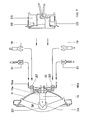
- Die gestellte Aufgabe wird durch die im Kennzeichen des Hauptanspruchs aufgeführten Merkmale gelöst. Vorteilhafte Ausgestaltungen sind in den Unteransprüchen wiedergegeben. Weitere Einzelheiten können der nachfolgenden Beschreibung mit Zeichnungen entnommen werden. Von den Figuren zeigen
- Figur 1 eine bekannte Reflektorlampe in Seitenansicht
- Figur 2 die neuerungsgemäße Reflektorlampe im Schnitt
- Figur 3 den Scheitelbereich des Reflektors der Lampe nach Figur 2 in Seitenansicht
- Figur 4 die Lampe nach Figur 2 in Rückansicht
- Figur 5 einen Schnitt des Sockelsteines
- Figur 6 ein Flachstück mit Kappe in Draufsicht
- Figur 7 die Lampe nach Figur 2 mit elektrischen Anschlußmöglichkeiten
- Die bekannte, in Sealed Beam-Technik gefertigte Reflektorlampe (Figur 1) weist als Reflektor den schweren verspiegelten Preßglaskörper 1 auf. Der gasgefüllte Reflektorraum ist durch die vakuumdicht aufgesetzte transparente gewichtige Frontscheibe 2 aus Glas gegen außen abgeschlossen. Die Ringstufe 3 der Frontscheibe 2 dient zum lagerichtigen Anordnen der Lampe in Leuchten. Stromzuführungen 4 tragen die Glühwendel 5 sowie eine Abdeckung 6, die unerwünschtes Streulicht verhindert. Die Enden der Stromzuführungen sind durch Reflektor- öffnungen geführt und in den metallischen Anschlußkappen 7 verlötet, die in den Preßglaskörper 1 luftdicht eingeschmolzen sind. Auf den Anschlußkappen 7 sind die Kontaktbleche 8 befestigt. Befestigungsschrauben 9 dienen zum Anschließen der Lampe an elektrische Stromzuleitungen. Die Ausbildung der Kontaktbleche 8 erlaubt auch einen direkten elektrischen Kontakt mit einer für diese Lampen vorgesehenen bekannten Lampenfassung 23 (Figur 7). Beispielsweise in den USA sind diese Reflektorlampen und die ihnen zugeordneten Fassungen im Handel.
- Demgegenüber besitzt die in ihren äußeren Abmessungen der bekannten Lampe angepaßte erfindungsgemäße Reflektorlampe einen leichten Metallreflektor 11 aus dünnem, etwa 0,8 mm - 1 mm, vorzugsweise 0,8 mm dicken Blech aus Reinaluminium mit glatter, glanzeloxierter parabolischer Innenfläche. Eine Frontscheibe fehlt. Die Aufgabe der Ringstufe 3 der bekannten Lampe übernimmt ein Stülprand 10, der dem Reflektor 11 angeformt ist. Die Bautiefe des Reflektors 11 beläuft sich im Scheitel auf maximal 30 mm. Im Scheitel des Reflektors 11 ist eine kreisrunde Öffnung 11a, die ein rückseitig aufgesetzter Sockelstein 12 (Figuren 2, 4) aus temperaturbeständigem Material, beispielsweise Keramik abdeckt. Der Sockelstein 12, dessen erhabenes Mittelstück 12a die Öffnung 11a durchsetzt, ist im wesentlichen quaderförmig. Er ist mit seiner Auflagefläche dem Verlauf der Reflektorkrümmung angepaßt und ist über vier Laschen 13 aufgeschoben, die dem Reflektor 11 in dessen Scheitelbereich angeformt sind (Figur 3). Zum Befestigen des Sockelsteins 12 sind die überstehenden Laschenenden verdreht. Eine Halogenglühlampe 14 (6 V, 35 W), mit deren Hilfe gegenüber den bekannten Reflektorlampen eine höhere axiale Lichtstärke erzielbar ist, ist im Scheitel des Reflektors 11 angeordnet und ersetzt die Glühwendel 5 der bekannten Lampe. Die Halogenglühlampe 14 wird an ihren äußeren Stromzuführungen 15 von Kontaktfahnen 16 gehalten, die in eine zentrale rechteckige Öffnung 17 des Sockelsteins 12 hineinragen. Die Stromzuführungen 15 sind angeschweißt. Die Kontaktfahnen 16 sind mit dem Sockelstein 12 vernietet und haben seitliche Führungslappen 18, mit denen sie ihre Unterlage umgreifen, wodurch sie gegen Verdrehen gesichert sind (Figur 5). Zum Anklemmen von Kabelschuhen 19 elektrischer Stromversorgungsleitungen tragen die Kontaktfahnen Klemmschrauben 20. Die Enden 16a der Kontaktfahnen 16 sind zu Flachsteckern geformt. Sie sind zur Aufnahme elektrischer Anschlußsteckhülsen 21 geeignet bzw. erlauben den Einsatz der erfindungsgemäßen Reflektorlampe in die bekannte Fassung 23. Bei in die Fassung 23 eingesetzter Lampe ist die Fassung über den Sockelstein 12 geschoben und die Kontaktfahnen 16 kontaktieren die Kontaktelemente 22 der Fassung 23. Zur Abschirmung von Direktstrahlung ist die Lampenkuppe 24 von einer Kappe 25 umfaßt. Die Kappe 25 dient zur Abschirmung von Direktstrahlung. Sie ist mittels eines Flachstückes 26 am Reflektor 11 befestigt, das sich brückenbogenartig von Reflektorseite zu Reflektorseite spannt (Figur 6).
Claims (9)
Applications Claiming Priority (2)
| Application Number | Priority Date | Filing Date | Title |
|---|---|---|---|
| DE8310715U | 1983-04-12 | ||
| DE19838310715U DE8310715U1 (de) | 1983-04-12 | 1983-04-12 | Reflektorlampe |
Publications (3)
| Publication Number | Publication Date |
|---|---|
| EP0121819A2 true EP0121819A2 (de) | 1984-10-17 |
| EP0121819A3 EP0121819A3 (en) | 1985-10-30 |
| EP0121819B1 EP0121819B1 (de) | 1988-01-27 |
Family
ID=6752207
Family Applications (1)
| Application Number | Title | Priority Date | Filing Date |
|---|---|---|---|
| EP84102812A Expired EP0121819B1 (de) | 1983-04-12 | 1984-03-15 | Reflektorlampe |
Country Status (4)
| Country | Link |
|---|---|
| US (1) | US4623815A (de) |
| EP (1) | EP0121819B1 (de) |
| JP (1) | JPS59173260U (de) |
| DE (2) | DE8310715U1 (de) |
Families Citing this family (9)
| Publication number | Priority date | Publication date | Assignee | Title |
|---|---|---|---|---|
| DE3603743A1 (de) * | 1986-02-06 | 1987-08-13 | Patent Treuhand Ges Fuer Elektrische Gluehlampen Mbh | Hochdruckentladungslampe fuer die verwendung in kraftfahrzeugscheinwerfern |
| DE8803881U1 (de) * | 1988-03-22 | 1988-05-11 | Patent-Treuhand-Gesellschaft für elektrische Glühlampen mbH, 8000 München | Kompakte Reflektorlampe |
| US4924134A (en) * | 1988-08-15 | 1990-05-08 | Gte Products Corporation | Internal lamp reflector |
| US4964829A (en) * | 1988-08-15 | 1990-10-23 | Gte Products Corporation | Internal lamp reflector |
| US20030201703A1 (en) * | 2002-04-30 | 2003-10-30 | Makoto Horiuchi | High pressure discharge lamp, lamp with reflecting mirror and image projecting device |
| DE10251960A1 (de) * | 2002-11-08 | 2004-05-19 | Philips Intellectual Property & Standards Gmbh | Reflektorlampe |
| DE10302931A1 (de) | 2003-01-24 | 2004-07-29 | Patent-Treuhand-Gesellschaft für elektrische Glühlampen mbH | Reflektor und Reflektorlampe |
| JP5283380B2 (ja) * | 2004-07-27 | 2013-09-04 | コーニンクレッカ フィリップス エレクトロニクス エヌ ヴィ | 一体型反射器ランプ |
| US9068723B2 (en) * | 2012-07-21 | 2015-06-30 | Dean Andrew Wilkinson | Configurable lamp assembly |
Family Cites Families (11)
| Publication number | Priority date | Publication date | Assignee | Title |
|---|---|---|---|---|
| DE2321709C3 (de) | 1973-04-28 | 1975-10-16 | Philips Patentverwaltung Gmbh, 2000 Hamburg | Elektrische Strahlerlampe, insbesondere für den Einsatz als Fahrzeugscheinwerfer, und Verfahren zu ihrer Herstellung |
| DE2323520A1 (de) * | 1973-05-10 | 1974-11-28 | Bosch Gmbh Robert | Gasdichter scheinwerfer fuer kraftfahrzeuge |
| DE2818743A1 (de) * | 1977-05-04 | 1978-11-09 | Carello & C Spa Fausto | Scheinwerfer, insbesondere nebelscheinwerfer fuer kraftfahrzeuge |
| JPS5418084U (de) * | 1977-07-08 | 1979-02-05 | ||
| DE2834968A1 (de) | 1978-08-10 | 1980-02-21 | Philips Patentverwaltung | Abgedichteter scheinwerfer, insbesondere fuer kraftfahrzeuge, und verfahren zu seiner herstellung |
| US4282565A (en) * | 1979-07-16 | 1981-08-04 | General Electric Company | Sealed, prefocused mount for plastic PAR lamp |
| US4287448A (en) | 1979-07-16 | 1981-09-01 | General Electric Company | Mechanical stop means for a prefocused plastic PAR lamp |
| JPS5640442A (en) * | 1979-09-12 | 1981-04-16 | Kobe Steel Ltd | Treatment of steel production slag |
| JPS5715471A (en) * | 1980-07-02 | 1982-01-26 | Hitachi Ltd | Junction type field effect semiconductor device and manufacture thereof |
| DE3101640A1 (de) | 1981-01-20 | 1982-08-26 | Patent-Treuhand-Gesellschaft für elektrische Glühlampen mbH, 8000 München | Sealed beam-scheinwerfer |
| US4507712A (en) | 1983-06-24 | 1985-03-26 | Dolan Richard J | Method of making replaceable lamp unit for automotive headlight |
-
1983
- 1983-04-12 DE DE19838310715U patent/DE8310715U1/de not_active Expired
-
1984
- 1984-03-15 EP EP84102812A patent/EP0121819B1/de not_active Expired
- 1984-03-15 DE DE8484102812T patent/DE3469107D1/de not_active Expired
- 1984-04-02 US US06/596,015 patent/US4623815A/en not_active Expired - Fee Related
- 1984-04-12 JP JP1984052789U patent/JPS59173260U/ja active Granted
Also Published As
| Publication number | Publication date |
|---|---|
| EP0121819A3 (en) | 1985-10-30 |
| JPS59173260U (ja) | 1984-11-19 |
| DE8310715U1 (de) | 1983-12-22 |
| DE3469107D1 (en) | 1988-03-03 |
| US4623815A (en) | 1986-11-18 |
| JPH0436054Y2 (de) | 1992-08-26 |
| EP0121819B1 (de) | 1988-01-27 |
Similar Documents
| Publication | Publication Date | Title |
|---|---|---|
| EP0334208B1 (de) | Kompakte Reflektorlampe | |
| EP0121819B1 (de) | Reflektorlampe | |
| DE4223643A1 (de) | Einseitig gesockelte Hochdruckentladungslampe | |
| DE2952535A1 (de) | Entladungslampe | |
| DE3635808C2 (de) | ||
| EP1006550B1 (de) | Elektrische Lampe und Beleuchtungsvorrichtung mit einer derartigen elektrischen Lampe | |
| EP0078030B1 (de) | Elektrische Lampe | |
| EP1009012B1 (de) | Elektrische Lampe | |
| DE3025173A1 (de) | Elektrische lampe | |
| DE102007035597A1 (de) | Elektrische Lampe mit einem Außenkolben und einer im Außenkolben angeordneten Einbaulampe | |
| DE10122878B4 (de) | Beleuchtungseinrichtung für Backöfen | |
| DE7321153U (de) | ||
| DE202011100723U1 (de) | Lampe | |
| EP1051720B1 (de) | Elektrische lampe für einen fahrzeugscheinwerfer | |
| DE8905690U1 (de) | Vorrichtung zum Beleuchten von aufblasbaren Ballonen | |
| CH680684A5 (en) | Anti dazzle light fitting suitable for halogen bulbs | |
| EP1515085B1 (de) | UV-Lampenanordnung und deren Verwendung | |
| EP0678706B1 (de) | Deckeneinbauleuchte | |
| DE60312675T2 (de) | Leuchteinheit | |
| DE2105587A1 (de) | Fahrzeug-Scheinwerfer | |
| DE487364C (de) | Elektrisches Reklameschild | |
| DE827528C (de) | Stiftsockelfassung fuer Leuchtstofflampen mit seitlichem Befestigungsansatz und mit Lampenende und Fassung abdeckender Manschette | |
| DE10116255B4 (de) | Scheinwerfer für Fahrzeuge | |
| DE2504991A1 (de) | Zusatzscheinwerfer, insbesondere fuer kraftfahrzeuge | |
| DE19811420A1 (de) | Seitliche Blinkleuchte |
Legal Events
| Date | Code | Title | Description |
|---|---|---|---|
| PUAI | Public reference made under article 153(3) epc to a published international application that has entered the european phase |
Free format text: ORIGINAL CODE: 0009012 |
|
| AK | Designated contracting states |
Designated state(s): BE DE FR GB IT |
|
| 17P | Request for examination filed |
Effective date: 19850228 |
|
| PUAL | Search report despatched |
Free format text: ORIGINAL CODE: 0009013 |
|
| AK | Designated contracting states |
Designated state(s): BE DE FR GB IT |
|
| 17Q | First examination report despatched |
Effective date: 19870624 |
|
| GRAA | (expected) grant |
Free format text: ORIGINAL CODE: 0009210 |
|
| AK | Designated contracting states |
Kind code of ref document: B1 Designated state(s): BE DE FR GB IT |
|
| REF | Corresponds to: |
Ref document number: 3469107 Country of ref document: DE Date of ref document: 19880303 |
|
| ET | Fr: translation filed | ||
| ITF | It: translation for a ep patent filed | ||
| GBT | Gb: translation of ep patent filed (gb section 77(6)(a)/1977) | ||
| PLBE | No opposition filed within time limit |
Free format text: ORIGINAL CODE: 0009261 |
|
| STAA | Information on the status of an ep patent application or granted ep patent |
Free format text: STATUS: NO OPPOSITION FILED WITHIN TIME LIMIT |
|
| 26N | No opposition filed | ||
| ITTA | It: last paid annual fee | ||
| REG | Reference to a national code |
Ref country code: GB Ref legal event code: IF02 |
|
| PGFP | Annual fee paid to national office [announced via postgrant information from national office to epo] |
Ref country code: GB Payment date: 20030307 Year of fee payment: 20 |
|
| PGFP | Annual fee paid to national office [announced via postgrant information from national office to epo] |
Ref country code: BE Payment date: 20030314 Year of fee payment: 20 |
|
| PGFP | Annual fee paid to national office [announced via postgrant information from national office to epo] |
Ref country code: FR Payment date: 20030328 Year of fee payment: 20 |
|
| PGFP | Annual fee paid to national office [announced via postgrant information from national office to epo] |
Ref country code: DE Payment date: 20030519 Year of fee payment: 20 |
|
| PG25 | Lapsed in a contracting state [announced via postgrant information from national office to epo] |
Ref country code: GB Free format text: LAPSE BECAUSE OF EXPIRATION OF PROTECTION Effective date: 20040314 |
|
| BE20 | Be: patent expired |
Owner name: *PATENT-TREUHAND-G. FUR ELEKTRISCHE GLUHLAMPEN M.B Effective date: 20040315 |
|
| REG | Reference to a national code |
Ref country code: GB Ref legal event code: PE20 |