EP0121865A2 - Montage pour installations de télécommunication, en particulier pour centraux téléphoniques comprenant des processeurs d'informations et des dispositifs pour éviter des surcharges - Google Patents
Montage pour installations de télécommunication, en particulier pour centraux téléphoniques comprenant des processeurs d'informations et des dispositifs pour éviter des surcharges Download PDFInfo
- Publication number
- EP0121865A2 EP0121865A2 EP84103444A EP84103444A EP0121865A2 EP 0121865 A2 EP0121865 A2 EP 0121865A2 EP 84103444 A EP84103444 A EP 84103444A EP 84103444 A EP84103444 A EP 84103444A EP 0121865 A2 EP0121865 A2 EP 0121865A2
- Authority
- EP
- European Patent Office
- Prior art keywords
- switching
- information
- control unit
- central
- overload
- Prior art date
- Legal status (The legal status is an assumption and is not a legal conclusion. Google has not performed a legal analysis and makes no representation as to the accuracy of the status listed.)
- Granted
Links
Images

Classifications
-
- H—ELECTRICITY
- H04—ELECTRIC COMMUNICATION TECHNIQUE
- H04Q—SELECTING
- H04Q3/00—Selecting arrangements
- H04Q3/42—Circuit arrangements for indirect selecting controlled by common circuits, e.g. register controller, marker
- H04Q3/54—Circuit arrangements for indirect selecting controlled by common circuits, e.g. register controller, marker in which the logic circuitry controlling the exchange is centralised
- H04Q3/545—Circuit arrangements for indirect selecting controlled by common circuits, e.g. register controller, marker in which the logic circuitry controlling the exchange is centralised using a stored program
- H04Q3/54575—Software application
- H04Q3/54591—Supervision, e.g. fault localisation, traffic measurements, avoiding errors, failure recovery, monitoring, statistical analysis
-
- H—ELECTRICITY
- H04—ELECTRIC COMMUNICATION TECHNIQUE
- H04M—TELEPHONIC COMMUNICATION
- H04M3/00—Automatic or semi-automatic exchanges
- H04M3/22—Arrangements for supervision, monitoring or testing
- H04M3/36—Statistical metering, e.g. recording occasions when traffic exceeds capacity of trunks
- H04M3/365—Load metering of control unit
Definitions
- the invention relates to a circuit arrangement for telecommunications systems, in particular telephone switching systems, with central information processing devices and sub-central switching devices assigned to them, the information coming from information sources different from each switching device and accordingly consisting of information portions limited, in particular dialing information, of an information processing device which is respectively assigned to the switching devices forward limited capacity in terms of information processing capacity, and with facilities for determining the information processing traffic load and for the detection of information processing traffic congestion, and with a defense against such information processing traffic congestion serving and provided in the sub-central switching devices, which in accordance with the traffic load Control signals are switched forward and switched backwards at regular intervals corresponding to the information processing capacity, and form an overload criterion when a limit value is reached.
- the number of computer requests and thus the influx of information to be processed in the computer can be restricted or temporarily stopped entirely on the basis of the load results recorded in each of the time segments by counting and determined each time after the end of the same by comparison.
- This is to optimally adapt the traffic load to the due date and overload limits of the computer, in order to achieve as much utilization of the computer capacity as possible, as well as to avoid overloading as far as possible, which is known to result in significant temporary operating restrictions or malfunctions for the facilities using the computer May have consequence.
- This is improved in the use cases addressed by the lecture by dynamically adapting the traffic load to the changing type and therein the frequency of the computing jobs fed to the computer.
- the known methods for detecting and regulating the computer load only provide a sufficiently accurate result if the individual time period used for counting the relevant events, for example computer requests, is large enough in relation to the mean time interval between these events, So that fluctuations in the computer load, which rises and falls continuously, this computer load is not shown in rough jumps, so that a corresponding regulation can optimally adapt the computer load to the load capacity.
- the underlying requirement is that the time period for the individual count the events must be large enough, has a negative effect on the respective time of availability of the results of each of the counting processes.
- the result of the determination of the computer load therefore always shows a time delay, which is inevitably due to the fact that for each acquisition period the result corresponding to it is only determined after it has expired, specifically by means of a comparison process.
- the object of the invention is therefore to create more favorable conditions for the early detection of overload situations in order not only to avoid overloading the central information processing device with greater certainty, but also to avoid unnecessary and disadvantageous overload protection measures which lead to a loss of performance in the central information processing device can lead.
- the invention solves the problem in that the determination of the traffic load and the detection of overload situations takes place in the sub-central switching devices, namely by means of the counters provided therein, and that the control signals, which govern the counters forming the overload criterion, concern the traffic load at the beginning one received in a sub-central switching device, to be stored in it and to be returned to the central information processing device, in particular announcing this beginning by being initial switching indicators, in particular control characters derived from them, each of which announces the subsequent arrival of an information portion to be processed.
- the invention therefore takes a different route than relevant known arrangements for overload protection.
- the invention makes use of the counter known from the aforementioned publication, it does not supply overload signals determined in any other way; but uses them to form the overload signals; Instead of overload signals, according to the invention, these counters rather receive control signals which, in each case in a sub-central switching device, each represent the beginning of a received portion of information which is to be temporarily stored here and to be forwarded to the central information processing device. The determination of the overload situation is therefore not carried out in the central information processing, but in each of the sub-central switching devices, where the corresponding overload protection measures are then also taken for each sub-central switching device.
- FIG. 1 and 2 of the drawings an embodiment of the invention is shown only in components which contribute significantly to its understanding.
- the description first of all deals with the general functional sequences of a PCM telephone switching system according to the invention shown in FIG. 1. Only further below are the special features of this switching system according to the invention additionally explained with reference to FIG. 2.
- a switching matrix constructed in three switching stages RZE, R and RZA has a larger number of switching matrix connections on the input side, one of which is shown and labeled A.
- the switching matrix consists of several switching matrix parts.
- Each of the switching matrix connections always comprises a pair of time-division multiplex lines, of which one time-division multiplex line is used for signal transmission to the switching matrix and the other time-division multiplexing line is used for signal transmission from the switching matrix.
- the switching matrix connection A comprises a time-division multiplex line A1 and a time-division multiplex line A2.
- the respective signal transmission direction is indicated by corresponding arrows for each of these two time-division multiplex lines.
- the coupling multiples of the first coupling stage RZE are combined time-space multiples, such as the Darge symbols.
- the coupling multiples of the middle coupling stage R are spatial position multiples.
- the coupling multiples of the last coupling stage RZA are space-time-multiples again.
- a larger number of the specified multiples is provided in each coupling stage, although only three multiples of the specified type are shown for each coupling stage.
- the coupling multiples of the different coupling stages are connected to one another via intermediate lines in the manner shown in the drawing. These intermediate lines are time division intermediate lines.
- the switching network connections are also time-multiplexed.
- connection groups e.g. the connection group LTG1 (Line Trunk Group), individually connected.
- connection group LTG1 Line Trunk Group
- a connection group can be connected on the input side with subscriber lines (analog), analog connecting lines and with PCM connecting lines (alternatively and also in combination).
- a subscriber station connected via a subscriber line is designated T1.
- a line group includes encoders, decoders, multiplexers, demultiplexers and the facilities required to implement the so-called BORSCHT functions (cf. NTZ vol.
- connection group LTG1 is shown in the drawing. Their structure and mode of operation are described in detail in DT-OS 28 26 113 from page 6 below Please note the booklet for the 4th year (1981) of the magazine "telcom report”. The further explanations assume that these descriptions are known and are limited to the relationships that are particularly important in the present case.
- a central control unit ZW is used, among other things, to establish the communications connections to be set up over the switching matrix. It determines the switching data required to establish each connection. As is known, the switching data for a connection to be switched through specifies exactly the course of the connection in question via the switching matrix, that is to say the switching matrixes and intermediate lines traversed by the connection, and the channels occupied therein. This mediation data is generated with the help of the central control unit, which also performs the function of a route search device and occupancy memory, elaborates and transmits it to the switching matrix setting device KE of the switching matrix K.
- the buffer device can be limited to a part of these functions or to only one of these functions at a time. Such a buffer device is e.g. described in detail in DE-PS 15 37 849 (VPA 67/3047).
- a larger number of decentralized control devices GP1 to GPn are shown, each of which is individually assigned to the line trunk groups LTG1 to LTGn. These control devices are used to carry out all switching operations within each of the connection groups mentioned. To this Switching operations include in particular all switching operations within these line groups. Further details on this can be found in the previously mentioned DE-OS 28 26 113.
- the decentralized control devices GP1 to GPn are connected to the central control unit ZW via data channels which are individually switched through per decentralized control device via the switching matrix (K) to the buffer device MB.
- a separate data channel leads from this buffer device, namely from its data header ML, to each of the decentralized control devices.
- the buffer device MB with its data head ML is connected to one of the switching matrix connections via a time-division multiplex line m.
- the buffer device is connected to one of the switching matrix connections of the switching matrix in the same way as each of the connection groups LTG1 to LTGn mentioned.
- the time-division multiplex line m is therefore connected to a switching matrix connection, which comprises a time-division multiplex input to a space-position multiple of the first switching stage and a time-division multiplex output from a space-multiple of the last switching stage.
- the time-division multiplexing device m is therefore connected to a switching network connection such as that designated by A.
- Any data connection between the header of a buffer device and each of the line groups, e.g. the line trunk group LTG1, comprises a channel for the transmission of data from the buffer device to the relevant line trunk group and a further channel for the transmission of data in the opposite direction.
- These two data channels lead to and from the decentralized control device individually assigned to the relevant line group.
- the establishment and maintenance of the explained data connections via the switching matrix K is carried out with the aid of the switching matrix setting device KE in the same way as the establishment and maintenance of communication links, for example telephone connections.
- the switching matrixes of the switching matrix K are assigned latches, into which the switching data relating to a switching matrix are stored. With the help of this latch ensures that the required interconnections are available in the respective time slots or that the required write operations and read operations for the full memories of the time slot multiples take place. All further details relating to the structure and mode of operation of a time-division multiplex switching arrangement are assumed to be known here and are therefore not described in further detail.
- the switching data required for establishing message connections are transmitted from the central control unit via the buffer device MB to the switching matrix setting device KE.
- a data header MK which is assigned to the buffer device MB.
- a plurality of switching matrix setting devices' KE can also be connected to a buffer device MB.
- These multiple switching matrix setting devices can be individually assigned to several switching matrix parts of a larger switching matrix. It is also possible to provide a switching matrix setting device for each switching stage.
- the switching matrix setting device KE is also in one their assigned memory V contains setting data, that is to say the switching data, stored for the data channels.
- this switching data does not therefore have to be reworked by the central control unit ZW and does not have to be retransmitted via the buffer device MB.
- the central control unit ZW merely issues a corresponding command to the buffer device MB, which it sends to the Coupling field setting device KE passes on, and on the basis of which it takes the switching data stored in its memory V, in order to carry out the necessary switching processes one after the other in a manner known per se.
- the time channel coupler TSU of the connection group LTG1 in addition to communication connections from and to subscriber stations and connecting lines, also the data connections already mentioned between the decentralized control devices, for example GP, assigned to the connection groups, for example LTG1. on the one hand and the central control unit ZW on the other. As already explained, these data connections continue to run over the switching matrix K and the time-division multiplex line m.
- the group control units GP1 to GPn are decentralized or partially centralized control units in comparison to the central control unit ZW. Overall, these sub-central control units and the central control unit are also referred to as switching units.
- the group control units and the central control unit have a limited capacity in terms of information capacity. The performance of the central control unit poses a particular problem.
- a number of line trunk groups LTG1 to LTGn are provided.
- Each of these connection groups is connected via a PCM line, e.g. ltgl, connected to an input of the switching matrix K in the manner described.
- This PCM line per line group leads within it to a switching device TSU, the meaning and mode of operation of which is described in more detail in the aforementioned German Offenlegungsschrift 2,826,113.
- This switching arrangement is a sub-switching network via which both the data connections mentioned and the connections from and to subscribers and from and to connecting lines are switched through.
- Connection lines are of course also understood to mean channels of connected PCM connection lines. The connection of these subscriber lines, connecting lines and channels can be found in the literature references already mentioned.
- the group control unit is used in a manner known per se to process the reception of such incoming connection-specific information.
- a group control unit also carries out processing or preprocessing of this recorded information in each case in association with the relevant subscriber line, connecting line or the relevant channel.
- some such information is temporarily stored in the memory SP individually assigned to the group control unit, with the aid of an input / output device IOP.
- the group control unit also has the task of transmitting signals and control signals via these lines (subscriber lines and connecting lines, as well as channels), for example ringing alternating current pulses, audible signals, dialing indicators and line characters and the like.
- connections with regard to the direction of connection establishment both arrive from a line (subscriber line, connecting line or a corresponding channel) to the central switching network. K switched through and from this to such a line.
- a connection is first made, for example, from a subscriber line via the relevant connection group to the central switching matrix K.
- the data required for the further connection of the relevant connection via this switching matrix is transmitted from the group control unit to the central control unit ZW via the relevant data connection already mentioned.
- the further connection switching takes place via a line group (possibly the same line group, but usually one other line group) for which the relevant group 'control unit of the respective line group must act.
- connection setup direction there are switching operations of various types with regard to the connection setup direction, namely connections on the one hand from a subscriber line or connecting line (or a corresponding channel) to the switching matrix K and on the other hand connections in the opposite direction.
- the interconnections over a sub-switching matrix also differ in those from and to subscriber lines on the one hand and from and to connecting lines (or channels) on the other hand.
- the information acquisition processes and / or information delivery processes carried out in connection with these two switching processes required for each connection take up the respective group control unit at least once per switching process.
- the respective type of switching (incoming or outgoing) from or to the subscriber line or connecting line) is decisive for the information processing traffic load per switching process that is inevitably associated with the respective use of the group control unit - as already stated, the group control units provide the information they have in the Record connection with a switching process, forwarded unchanged or preprocessed to the central control unit common to them. Likewise, the central control unit also outputs information to the group control units in order to carry out outgoing connections required therein and to emit signals and control signals via the relevant lines (subscriber lines) and connecting lines or channels.
- the pro Establishing a connection from a group control unit to the central control unit thus represents a portion of information of limited scope; the respective scope of a portion of information results from the respective type of connection.
- Each such work is identified by an initial switching indicator for the respective group control unit.
- Such an initial switching indicator is, for example, the end of the loop, which represents the call signal, in the case of a subscriber line with a loop pulse.
- Such an initial switching indicator for a connecting line is, for example, the c-wire occupancy signal when the occupancy arrives. The same applies to connection-specific channels. These initial switching indicators are therefore different from one another, depending on the type of line concerned (subscriber line or connecting line).
- the extent of the information processing traffic load per connection is different for the central control unit, depending on the type the connection to be established in each case.
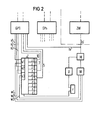
- FIG. 2 This indicates the group control unit PP1 and GPn and the central control unit ZW, which are also shown in FIG. 1.
- a counter Z is assigned to the group control unit GP1. The same applies to the other group control units.
- a group control unit Every time a group control unit is used for an information recording when a call is made by a subscriber who wishes to establish a connection, or if a connecting line (or a channel) is seized in order to put through a connection via the sub-switching network corresponding to the group control unit and the group control unit is used for the inclusion of dialing codes, as well as for the processing of the interconnection via the respective sub-switching matrix or if a through-routing is to be carried out from the switching matrix to an outgoing connection line (or a channel) or to a subscriber line and the corresponding information are to be received by the central control unit, an initial switching indicator is generated in the group control unit concerned, which always announces the subsequent arrival of information to be processed.
- a group control unit now always sends a control signal to the counter Z assigned to it when such an initial switching identifier is present, via one of the control lines x1, x2 or x3.
- R depending on which A is as the group controller then arising information processing traffic load T is the control signal via the control line x1 or the control line x2 or the control line x3 is given by the group control unit to the counter Z.
- the counter Z is advanced by a few steps. Switching the counter forwards and backwards results in one of its counter elements z1 to z10 being marked.
- the marking progresses in the ascending sense with regard to the numbering of the designations of the counter elements, and when the counter is switched backwards, the marking proceeds in the opposite sense.
- the number of steps by which the counter Z is incremented each time an initial switching flag is received depends, inter alia, on the respective level of information processing traffic load to be expected for the group control unit. Accordingly, the initial switching flag arrives in each case via a specific one of the control lines x1 to x3, as a result of which the number of forward steps is also determined for the counter Z.
- "Co-determined" here means that the number of forward steps upon arrival of an initial switching flag does not depend solely on this is via which of the control lines x1 to x3 the initial switching indicator arrives. Instead, a value indication transmitted via value lines w1 to w3 is also decisive.
- the counter Z of a group control unit is used to determine the information processing traffic load of the respective group control unit Detection of information processing traffic congestion and to prevent such congestion. Since all connections are now not only switched through a sub-switching network, but also always via the central switching network, each use of a group control unit also results in the central control unit being used. Consequently, the determination of the information processing traffic load of each group control unit, the detection of information processing traffic overloads for this group control unit and the defense against such overloads from this group control unit also relates to the information processing traffic load of the central control unit, information processing traffic overloads for the same and the defense against such overloads from the central control unit.
- control units For the group control units and for the central control unit, the common term “switching units” has been used up to now, subsequently also referred to collectively as “control units".
- the resilience of each such control unit basically depends on its structure (structure and program execution) and on the type and scope of the information processing processes that are continuously transferred to it.
- the composition of information processing processes of various types can shift during the operation of a control unit. For example, local connections may have to be established at certain times of the day, while long-distance connections have to be established at certain other times of the day. Furthermore, there may be more short-term calls at certain times of the day and more long-term calls at other times of the day.
- Fig. 2 an expensive plant is provided per group and connected to it (via m) such measuring device designated with M. It receives the request signal every time it occurs via a measuring line m. The measuring device counts off the request signals in a manner known per se. From a central timer device r, it receives a start character and an end character, ie two time markings, which mark the measurement period via a coaster device U. The measuring device now determines the number of request signals from the respective group control unit arriving between two such time markings. It transmits this number to a comparison device W, in which a constant value is stored, with which the comparison device compares the information about the number of request signals. It is assumed that three different determination results are provided with regard to the resilience. This number is by no means binding, but can also be chosen larger. After each measuring time interval has elapsed, the comparison device W therefore outputs a determination result with regard to the load capacity of the control unit, which corresponds to the daytime operating conditions.
- a load capacity measurement is provided individually for each of the group control units GP1 to GPn. However, it is also or even possible to provide such a load capacity measurement for the central control unit. Furthermore, it can be provided that a load capacity measurement is provided only at the central control unit, and that the determination results obtained in the form of the value information from one of the central control units. assigned measuring device to the counters Z assigned to the group control units.
- the three different values per value measurement are also individually assigned to the three control lines x1 to x3 mentioned, one of which always transmits an initial switching indicator from the group control unit to the counter Z, thereby indicating which type and, accordingly, to what extent those transmitted with the grade Initial shift indicator is expected workload to come to the group control unit for processing the incoming information assigned to the initial shift indicator (see above!).
- the three control lines x1 to x3 x1 to x3 are assigned.
- Each of these three different different possible initial switching indicators is assigned one of the three values, of which the individual value says something about the resilience of the control unit in question, each with reference to the type indicated with each of the initial switching indicators and the corresponding one Extent of workload coming to the control unit.
- the three determined per measurement period Values now indicate the number of counting steps per forward switching of the counter that are to be carried out by the counter when an initial switching indicator is received.
- the number of counting steps that the counter executes in a forward-switching manner on the basis of an initial switching indicator is thus dependent both on the respective initial switching indicator and on the respective determination result of the load capacity measurement.
- each of the counters is supplied with a downward switching pulse by the central timer device r at regular time intervals, in which case the counter is switched back one step at a time.
- the marking of the counter z5 therefore corresponds to a limit value with regard to the upward count and the downward count of the counter; if it is exceeded by counting up the counter, there is an overload criterion in the counter until the limit value is reached again by the individual steps of the downward counting.
- the upward count based on an initial switching indicator takes into account the information processing traffic load to be expected for the relevant group control unit and also for the central control unit on the one hand, and the current load capacity of the central control unit on the other hand, namely by the number of counting steps carried out in the respective forward switching, and the fact that the counter is switched backwards at a constant speed, it is achieved that the recording of dialing marks by the group control unit is prevented for a certain period of time which corresponds to the processing time of the dialing information last recorded. This period of time is thus determined by the respective valency which is stored in the relevant valence memory element (v1, v2 or v3) for the relevant initial switching indicator.
- the counter Z therefore accumulates the initial switching indicators. If the counter reaches the limit value represented by the counter z5, there is an overload criterion in the marking of this counter or a counter of counter value. This is transmitted to the group control unit via the overload line 5. It is thus formed between an initial switching indicator leading to reaching the limit value and a first character assigned by it of corresponding information, that is to say incoming dialing indicator, and has the result that these characters are not accepted by the group control unit concerned; At the same time, the busy signal can be switched on for the subscriber concerned are so that it is indicated to him by means of an audible signal that delivery of dialing codes remains unsuccessful. The transmission of the overload criterion via line 5 therefore prevents the recording of dialing codes from calling subscribers.
- the transfer of the overload criterion from the counter to the group control unit is to have the effect that for the duration of the overload criterion, further initial switching indicators and corresponding incoming information, e.g. dialing indicators, are not accepted, but that information, whose previous initial switching indicator has resulted in the overload criterion being formed is still being accepted.
- the information associated with it is also always accepted if an initial switching indicator has still been accepted; only then are further initial switching indicators and the information assigned to them no longer accepted.
- a further overload line 7 is also provided.
- An overload criterion is only transmitted via this overload line if the meter reaches a correspondingly higher meter reading. The same applies to the overload line 10.
- an overload criterion transmitted via the overload line 5 is used to leave the group controller, not to accept dialing numbers from calling subscribers, and an overload criterion transmitted via the overload line 7 is also used for incoming signals Dialing lines no longer accept incoming dialing lines. Since the counter reading of the counter indicates the current load on the group control unit, the acceptance of dialing indicators from calling subscribers is blocked at a load level corresponding to the counter z5, but the acceptance is blocked of dialing codes of incoming connecting lines only when the load is higher. In the case of an even higher load condition, the acceptance of information which the group control unit is to receive from the central control unit can also be prevented.
- the determination of the traffic load and the detection of overload situations in the group control units is carried out by means of the counter provided in or at it and the cases of the use of the group control unit being recorded;
- the determination of the traffic load and the detection of overloads is carried out at a central location.
- the overload criterion generated by the counter via the overload lines 5 and 7 prevents the use of the group control unit for the purpose of receiving information for those interconnections via the sub-switching network of the relevant line trunk group which are those of the incoming type. Connections from the switching matrix K to a connection line or to a subscriber line, on the other hand, can still be handled, although the overload criterion is already pending via the overload lines 5 and 7.
- the overload line 10 serves to transmit an overload blocking criterion, which not only prevents the central control unit from accepting information, but can it should also be provided that information is also prevented from being sent to the relevant group control unit, in particular the handling of switching operations within a line trunk group.
- the application of the invention is not limited to PCM telephone switching systems, but can also be implemented in telecommunications switching systems using analog technology.
- an overload signal is emitted to the connection-specific switching device via which an initial switching indicator has arrived, which has led to the limit value being reached.
- the overload signal then causes the off Initial switching indicators and information characters that are to be processed and that arrive in connection-specific switching devices are not passed on from here. It is just as well possible to store an overload signal in association with a connection-specific switching device at a central location and in this way to ensure that information arriving in the connection-specific switch in question is not accepted.
- a sign in particular an audible signal
- a connection-specific switching device to which an over-signal was sent or for which an overload signal has been stored, which indicates that information signs are not received via the connection-specific switching device in question.
- This is primarily the busy signal.
- the generation of those for the central control unit is thus determined at a decentralized point, and not at a single decentralized point but in all group control units.
- the counters known per se from German Offenlegungsschrift 3,236,130 are used for this purpose.
- the determination of the information traffic load and the formation of overload signals are not carried out in a central location in any other way, and the overload signals are not will.
- the fact that the counters are supplied with initial switching indicators, specifically at a decentralized point saves time by means of a correspondingly early protection against overload.
- the overload case for a central control unit is therefore predictable and countermeasures can be taken so early that it can be prevented from the outset that the overload case occurs at all.
- the time interval between the initial switching indicator, which are fed to the counters, and the information individually assigned to the initial switching indicator (e.g. incoming dialing indicator), which in their entirety are the cause, for the information coming to the central control unit - Traffic load, shared.
- An existing overload criterion also does not lead to a general blocking of information for the central control unit, but rather leads to a defense against individual assignments, for example assignments caused by a subscriber call, which are randomly distributed over the entire traffic situation. This makes it possible to design the overload protection very precisely and to immediately render the temporarily taken countermeasures ineffective once a traffic congestion has occurred.
- the overload protection measures do not have a uniform effect on all cases of the use of the group control units, but instead differentiate these cases in the manner described with regard to incoming connections and outgoing connections via a sub-switching network corresponding to a group control group control unit, first of all the overload protection measures are achieved are effective in limiting the information processing traffic load, and secondly, avoiding the work already done on the part a sub-central switching device and afterwards by the central control unit can be rejected because of the rejection of a request from a sub-central group control unit for processing an outgoing connection, i.e. for establishing a connection for which information processing has already been performed by the group control unit and by the central control unit .
- the overload criterion existing when a certain meter reading value is reached means that when it occurs between an initial switching indicator and the incoming dialing information associated with it, the latter is prevented from being recorded or is still being recorded, on the other hand but the inclusion of a further initial switching indicator together with the associated dialing information is prevented.
- Both variants can be implemented both in the event that the overload criterion is processed in and by the group control unit itself and in the event that it is delivered to a connection-specific switching device (for example a connection set).
Landscapes
- Engineering & Computer Science (AREA)
- Computer Networks & Wireless Communication (AREA)
- Signal Processing (AREA)
- Exchange Systems With Centralized Control (AREA)
- Monitoring And Testing Of Exchanges (AREA)
- Data Exchanges In Wide-Area Networks (AREA)
Priority Applications (1)
| Application Number | Priority Date | Filing Date | Title |
|---|---|---|---|
| AT84103444T ATE32009T1 (de) | 1983-03-31 | 1984-03-28 | Schaltungsanordnung fuer fernmeldeanlagen, insbesondere fernsprechvermittlungsanlagen mit informationsverarbeitenden schaltwerken und einrichtungen zur abwehr von ueberbelastungen. |
Applications Claiming Priority (2)
| Application Number | Priority Date | Filing Date | Title |
|---|---|---|---|
| DE19833311866 DE3311866A1 (de) | 1983-03-31 | 1983-03-31 | Schaltungsanordnung fuer fernmeldeanlagen, insbesondere fernsprechvermittlungsanlagen mit informationsverarbeitenden schaltwerken und einrichtungen zur abwehr von ueberbelastungen |
| DE3311866 | 1983-03-31 |
Publications (3)
| Publication Number | Publication Date |
|---|---|
| EP0121865A2 true EP0121865A2 (fr) | 1984-10-17 |
| EP0121865A3 EP0121865A3 (en) | 1984-12-05 |
| EP0121865B1 EP0121865B1 (fr) | 1988-01-13 |
Family
ID=6195279
Family Applications (1)
| Application Number | Title | Priority Date | Filing Date |
|---|---|---|---|
| EP84103444A Expired EP0121865B1 (fr) | 1983-03-31 | 1984-03-28 | Montage pour installations de télécommunication, en particulier pour centraux téléphoniques comprenant des processeurs d'informations et des dispositifs pour éviter des surcharges |
Country Status (5)
| Country | Link |
|---|---|
| US (1) | US4626624A (fr) |
| EP (1) | EP0121865B1 (fr) |
| JP (1) | JPS59190768A (fr) |
| AT (1) | ATE32009T1 (fr) |
| DE (2) | DE3311866A1 (fr) |
Cited By (2)
| Publication number | Priority date | Publication date | Assignee | Title |
|---|---|---|---|---|
| EP0177735A3 (en) * | 1984-09-27 | 1986-06-11 | Siemens Aktiengesellschaft | Circuit arrangement for telecommunication installations, especially for telephone exchanges with centralized and/or decentralized information-processing devices |
| EP0756411A3 (fr) * | 1995-07-28 | 2000-01-19 | Alcatel SEL Aktiengesellschaft | Méthode et réseau de télécommunication pour commander des appels de masse |
Families Citing this family (14)
| Publication number | Priority date | Publication date | Assignee | Title |
|---|---|---|---|---|
| EP0213382B1 (fr) * | 1985-08-14 | 1990-01-24 | Siemens Aktiengesellschaft | Montage pour centraux de télécommunications, en particulier pour centraux téléphoniques équipés de processeurs de contrôle et de dispositifs de mesure de trafic |
| US5067074A (en) * | 1989-10-27 | 1991-11-19 | At&T Bell Laboratories | Control of overload in communications networks |
| JP3334972B2 (ja) * | 1992-11-20 | 2002-10-15 | キヤノン株式会社 | 構内交換装置 |
| AU690409B2 (en) * | 1994-12-29 | 1998-04-23 | Telefonaktiebolaget Lm Ericsson (Publ) | Method and apparatus for measuring loads in a common channel signalling link |
| KR960043938A (ko) * | 1995-05-27 | 1996-12-23 | 김광호 | 멀티프로세서 제어시스템의 단위 프로그램에 대한 메세지 과부하 제어방법 |
| US5933481A (en) * | 1996-02-29 | 1999-08-03 | Bell Canada | Method of controlling call traffic in a telecommunication system |
| US5719930A (en) * | 1996-07-08 | 1998-02-17 | Bell Canada | Method of volume screening signalling messages in a telecommunication system |
| DE69816053T2 (de) * | 1997-03-25 | 2004-06-03 | British Telecommunications Public Ltd. Co. | Telekommunikationsnetzwerk mit Überlastungssteuerung |
| US6356629B1 (en) * | 1999-02-02 | 2002-03-12 | Cisco Technology, Inc. | Switched virtual circuit controller setup congestion management strategy |
| US6956850B1 (en) | 1999-03-25 | 2005-10-18 | Cisco Technology, Inc. | Call record management for high capacity switched virtual circuits |
| US6625121B1 (en) | 1999-04-28 | 2003-09-23 | Cisco Technology, Inc. | Dynamically delisting and relisting multicast destinations in a network switching node |
| US8161182B1 (en) | 2000-01-26 | 2012-04-17 | Cisco Technology, Inc. | Managing network congestion using dynamically advertised congestion status |
| US7570584B1 (en) | 2002-03-29 | 2009-08-04 | Cisco Technology, Inc. | Network-wide congestion control of SPVC signaling messages |
| US20090060161A1 (en) * | 2007-08-29 | 2009-03-05 | Inmate Calling Solutions Llc D/B/A Icsolutions | Method and system to automatically block a telephone number |
Family Cites Families (8)
| Publication number | Priority date | Publication date | Assignee | Title |
|---|---|---|---|---|
| DE1537849B2 (de) * | 1967-10-19 | 1971-04-01 | Siemens AG, 1000 Berlin u 8000 München | Schaltungsanordnung fuer zentralgesteuerte fernmeldever mittlungsanlagen insbesondere fernsprechvermittlungs anlagen |
| US4200771A (en) * | 1978-10-06 | 1980-04-29 | Kraushaar Jonathan M | Traffic measuring device based on state transitions |
| US4224479A (en) * | 1979-02-21 | 1980-09-23 | Bell Telephone Laboratories, Incorporated | Method of controlling call traffic in a communication switching system |
| IT1128795B (it) * | 1980-06-03 | 1986-06-04 | Sip | Misuratore programmabile di traffico telefonico |
| DE3104002C2 (de) * | 1981-02-05 | 1984-01-26 | Siemens AG, 1000 Berlin und 8000 München | Schaltungsanordnung für Fernmeldevermittlungsanlagen, insbesondere PCM-Fernsprechvermittlungsanlagen, mit einer Zeitmultiplexkoppelanordnung mit Zeitlagenvielfachen |
| NL8202419A (nl) * | 1982-06-15 | 1984-01-02 | Philips Nv | Werkwijze voor het voorkomen van overbelasting van de centrale besturing van een telecommunicatiesysteem en inrichting voor het uitvoeren van de werkwijze. |
| DE3236130A1 (de) * | 1982-09-29 | 1984-03-29 | Siemens AG, 1000 Berlin und 8000 München | Schaltungsanordnung fuer fernmeldeanlagen, insbesondere fernsprechvermittlungsanlagen mit zentralen informationsverarbeitungseinrichtungen mit ueberlastsignalaussendung |
| US4511762A (en) * | 1983-06-06 | 1985-04-16 | Siemens Corporate Research & Support, Inc. | Overload detection and control system for a telecommunications exchange |
-
1983
- 1983-03-31 DE DE19833311866 patent/DE3311866A1/de not_active Withdrawn
-
1984
- 1984-02-27 US US06/583,893 patent/US4626624A/en not_active Expired - Fee Related
- 1984-03-26 JP JP59056420A patent/JPS59190768A/ja active Granted
- 1984-03-28 AT AT84103444T patent/ATE32009T1/de not_active IP Right Cessation
- 1984-03-28 EP EP84103444A patent/EP0121865B1/fr not_active Expired
- 1984-03-28 DE DE8484103444T patent/DE3468806D1/de not_active Expired
Cited By (2)
| Publication number | Priority date | Publication date | Assignee | Title |
|---|---|---|---|---|
| EP0177735A3 (en) * | 1984-09-27 | 1986-06-11 | Siemens Aktiengesellschaft | Circuit arrangement for telecommunication installations, especially for telephone exchanges with centralized and/or decentralized information-processing devices |
| EP0756411A3 (fr) * | 1995-07-28 | 2000-01-19 | Alcatel SEL Aktiengesellschaft | Méthode et réseau de télécommunication pour commander des appels de masse |
Also Published As
| Publication number | Publication date |
|---|---|
| EP0121865A3 (en) | 1984-12-05 |
| JPH0340988B2 (fr) | 1991-06-20 |
| EP0121865B1 (fr) | 1988-01-13 |
| DE3311866A1 (de) | 1984-10-04 |
| DE3468806D1 (en) | 1988-02-18 |
| ATE32009T1 (de) | 1988-01-15 |
| US4626624A (en) | 1986-12-02 |
| JPS59190768A (ja) | 1984-10-29 |
Similar Documents
| Publication | Publication Date | Title |
|---|---|---|
| EP0121239B1 (fr) | Montage pour installations de télécommunication, en particulier pour centraux téléphoniques comprenant des processeurs d'informations et des dispositifs pour éviter des surcharges | |
| EP0121236B1 (fr) | Montage pour installations de télécommunication, en particulier pour centraux téléphoniques comprenant des processeurs d'informations et des dispositifs pour éviter des surcharges | |
| EP0121865B1 (fr) | Montage pour installations de télécommunication, en particulier pour centraux téléphoniques comprenant des processeurs d'informations et des dispositifs pour éviter des surcharges | |
| EP0121237B1 (fr) | Montage pour installations de télécommunication, en particulier pour centraux téléphoniques comprenant des processeurs d'informations et des dispositifs pour éviter des surcharges | |
| EP0121238B1 (fr) | Montage pour installations de télécommunication, en particulier pour centraux téléphoniques comprenant des processeurs d'informations et des dispositifs pour éviter des surcharges | |
| EP0205919B1 (fr) | Circuit pour centraux de télécommunication, en particulier des centraux téléphoniques comprenant des dispositifs de contrôle central recevant des ordres de traitement d'informations à partir de dispositifs de contrôle réparti | |
| EP0134010B1 (fr) | Circuit pour installations de télécommunications, en particulier centraux téléphoniques avec des circuits de traitement d'informations de contrôle centralisés et/ou partiellement centralisés | |
| EP0265817B1 (fr) | Procédé pour le contrôle du trafic dans des centraux de télécommunication, en particulier pour centraux téléphoniques équipés de processeurs de contrôle et de dispositifs de limitation de surcharge | |
| EP0169551B1 (fr) | Montage pour centraux de télécommunication, en particulier pour centraux téléphoniques avec des dispositifs de traitement d'informations et des dispositifs de mesure de trafic | |
| EP0134009B1 (fr) | Circuit pour installations de télécommunications en particulier centraux téléphoniques avec des circuits de traitement d'informations de contrôle | |
| DE3328575C2 (fr) | ||
| EP0176764B1 (fr) | Montage pour installations de télécommunication en particulier pour centraux téléphoniques comprenant des dispositif de traitement d'informations centralisés et/ou décentralisés | |
| EP0171784B1 (fr) | Circuit pour installations de télécommunications, en particulier centraux téléphoniques avec des circuits de traitement d'informations de contrôle centralisés et/ou décentralisés | |
| DE3328574C2 (de) | Schaltungsanordnung für Fernmeldeanlagen, insbesondere Fernsprechvermittlungsanlagen | |
| DE3311043A1 (de) | Verfahren und schaltungsanordnung zum herstellen von verbindungen zwischen teilnehmerstellen von vcermittlungsanlagen, insbesondere von datenvermittlungsanlagen | |
| DE3435497A1 (de) | Schaltungsanordnung fuer fernmeldevermittlungsanlagen, insbesondere fernsprechvermittlungsanlagen mit informationsverarbeitenden zentralen und/oder dezentralen schaltwerken | |
| EP0213382B1 (fr) | Montage pour centraux de télécommunications, en particulier pour centraux téléphoniques équipés de processeurs de contrôle et de dispositifs de mesure de trafic | |
| EP0091614B1 (fr) | Montage pour centraux de télécommunication, plus spécialement pour centraux téléphoniques, avec des circuits pour l'émission de signaux | |
| EP0177735B1 (fr) | Montage pour installations de télécommunication, en particulier pour centraux téléphoniques comprenant des dispositifs de traitement d'informations centralisés et/ou décentralisés | |
| DE3923169C2 (fr) | ||
| DE3736897C2 (fr) | ||
| CH677052A5 (fr) |
Legal Events
| Date | Code | Title | Description |
|---|---|---|---|
| PUAI | Public reference made under article 153(3) epc to a published international application that has entered the european phase |
Free format text: ORIGINAL CODE: 0009012 |
|
| PUAL | Search report despatched |
Free format text: ORIGINAL CODE: 0009013 |
|
| AK | Designated contracting states |
Designated state(s): AT CH DE FR GB LI NL SE |
|
| AK | Designated contracting states |
Designated state(s): AT CH DE FR GB LI NL SE |
|
| 17P | Request for examination filed |
Effective date: 19841221 |
|
| GRAA | (expected) grant |
Free format text: ORIGINAL CODE: 0009210 |
|
| AK | Designated contracting states |
Kind code of ref document: B1 Designated state(s): AT CH DE FR GB LI NL SE |
|
| REF | Corresponds to: |
Ref document number: 32009 Country of ref document: AT Date of ref document: 19880115 Kind code of ref document: T |
|
| REF | Corresponds to: |
Ref document number: 3468806 Country of ref document: DE Date of ref document: 19880218 |
|
| ET | Fr: translation filed | ||
| GBT | Gb: translation of ep patent filed (gb section 77(6)(a)/1977) | ||
| PLBE | No opposition filed within time limit |
Free format text: ORIGINAL CODE: 0009261 |
|
| STAA | Information on the status of an ep patent application or granted ep patent |
Free format text: STATUS: NO OPPOSITION FILED WITHIN TIME LIMIT |
|
| 26N | No opposition filed | ||
| PGFP | Annual fee paid to national office [announced via postgrant information from national office to epo] |
Ref country code: GB Payment date: 19910218 Year of fee payment: 8 |
|
| PG25 | Lapsed in a contracting state [announced via postgrant information from national office to epo] |
Ref country code: GB Effective date: 19920328 |
|
| GBPC | Gb: european patent ceased through non-payment of renewal fee | ||
| PGFP | Annual fee paid to national office [announced via postgrant information from national office to epo] |
Ref country code: AT Payment date: 19940223 Year of fee payment: 11 |
|
| PGFP | Annual fee paid to national office [announced via postgrant information from national office to epo] |
Ref country code: NL Payment date: 19940331 Year of fee payment: 11 |
|
| PGFP | Annual fee paid to national office [announced via postgrant information from national office to epo] |
Ref country code: CH Payment date: 19940617 Year of fee payment: 11 |
|
| EAL | Se: european patent in force in sweden |
Ref document number: 84103444.0 |
|
| PG25 | Lapsed in a contracting state [announced via postgrant information from national office to epo] |
Ref country code: AT Effective date: 19950328 |
|
| PG25 | Lapsed in a contracting state [announced via postgrant information from national office to epo] |
Ref country code: LI Effective date: 19950331 Ref country code: CH Effective date: 19950331 |
|
| PG25 | Lapsed in a contracting state [announced via postgrant information from national office to epo] |
Ref country code: NL Effective date: 19951001 |
|
| REG | Reference to a national code |
Ref country code: CH Ref legal event code: PL |
|
| NLV4 | Nl: lapsed or anulled due to non-payment of the annual fee |
Effective date: 19951001 |
|
| PGFP | Annual fee paid to national office [announced via postgrant information from national office to epo] |
Ref country code: SE Payment date: 19970321 Year of fee payment: 14 Ref country code: FR Payment date: 19970321 Year of fee payment: 14 |
|
| PGFP | Annual fee paid to national office [announced via postgrant information from national office to epo] |
Ref country code: DE Payment date: 19970521 Year of fee payment: 14 |
|
| PG25 | Lapsed in a contracting state [announced via postgrant information from national office to epo] |
Ref country code: SE Free format text: LAPSE BECAUSE OF NON-PAYMENT OF DUE FEES Effective date: 19980329 |
|
| PG25 | Lapsed in a contracting state [announced via postgrant information from national office to epo] |
Ref country code: FR Free format text: THE PATENT HAS BEEN ANNULLED BY A DECISION OF A NATIONAL AUTHORITY Effective date: 19980331 |
|
| PG25 | Lapsed in a contracting state [announced via postgrant information from national office to epo] |
Ref country code: DE Free format text: LAPSE BECAUSE OF NON-PAYMENT OF DUE FEES Effective date: 19981201 |
|
| EUG | Se: european patent has lapsed |
Ref document number: 84103444.0 |
|
| REG | Reference to a national code |
Ref country code: FR Ref legal event code: ST |