EP0121945A2 - Massagegerät - Google Patents
Massagegerät Download PDFInfo
- Publication number
- EP0121945A2 EP0121945A2 EP84104081A EP84104081A EP0121945A2 EP 0121945 A2 EP0121945 A2 EP 0121945A2 EP 84104081 A EP84104081 A EP 84104081A EP 84104081 A EP84104081 A EP 84104081A EP 0121945 A2 EP0121945 A2 EP 0121945A2
- Authority
- EP
- European Patent Office
- Prior art keywords
- guide rail
- base plate
- guide
- guide rails
- folded
- Prior art date
- Legal status (The legal status is an assumption and is not a legal conclusion. Google has not performed a legal analysis and makes no representation as to the accuracy of the status listed.)
- Granted
Links
Images








Classifications
-
- A—HUMAN NECESSITIES
- A61—MEDICAL OR VETERINARY SCIENCE; HYGIENE
- A61H—PHYSICAL THERAPY APPARATUS, e.g. DEVICES FOR LOCATING OR STIMULATING REFLEX POINTS IN THE BODY; ARTIFICIAL RESPIRATION; MASSAGE; BATHING DEVICES FOR SPECIAL THERAPEUTIC OR HYGIENIC PURPOSES OR SPECIFIC PARTS OF THE BODY
- A61H15/00—Massage by means of rollers, balls, e.g. inflatable, chains, or roller chains
-
- A—HUMAN NECESSITIES
- A61—MEDICAL OR VETERINARY SCIENCE; HYGIENE
- A61H—PHYSICAL THERAPY APPARATUS, e.g. DEVICES FOR LOCATING OR STIMULATING REFLEX POINTS IN THE BODY; ARTIFICIAL RESPIRATION; MASSAGE; BATHING DEVICES FOR SPECIAL THERAPEUTIC OR HYGIENIC PURPOSES OR SPECIFIC PARTS OF THE BODY
- A61H15/00—Massage by means of rollers, balls, e.g. inflatable, chains, or roller chains
- A61H15/0078—Massage by means of rollers, balls, e.g. inflatable, chains, or roller chains power-driven
-
- A—HUMAN NECESSITIES
- A61—MEDICAL OR VETERINARY SCIENCE; HYGIENE
- A61H—PHYSICAL THERAPY APPARATUS, e.g. DEVICES FOR LOCATING OR STIMULATING REFLEX POINTS IN THE BODY; ARTIFICIAL RESPIRATION; MASSAGE; BATHING DEVICES FOR SPECIAL THERAPEUTIC OR HYGIENIC PURPOSES OR SPECIFIC PARTS OF THE BODY
- A61H15/00—Massage by means of rollers, balls, e.g. inflatable, chains, or roller chains
- A61H2015/0007—Massage by means of rollers, balls, e.g. inflatable, chains, or roller chains with balls or rollers rotating about their own axis
- A61H2015/0014—Massage by means of rollers, balls, e.g. inflatable, chains, or roller chains with balls or rollers rotating about their own axis cylinder-like, i.e. rollers
-
- A—HUMAN NECESSITIES
- A61—MEDICAL OR VETERINARY SCIENCE; HYGIENE
- A61H—PHYSICAL THERAPY APPARATUS, e.g. DEVICES FOR LOCATING OR STIMULATING REFLEX POINTS IN THE BODY; ARTIFICIAL RESPIRATION; MASSAGE; BATHING DEVICES FOR SPECIAL THERAPEUTIC OR HYGIENIC PURPOSES OR SPECIFIC PARTS OF THE BODY
- A61H15/00—Massage by means of rollers, balls, e.g. inflatable, chains, or roller chains
- A61H2015/0007—Massage by means of rollers, balls, e.g. inflatable, chains, or roller chains with balls or rollers rotating about their own axis
- A61H2015/0014—Massage by means of rollers, balls, e.g. inflatable, chains, or roller chains with balls or rollers rotating about their own axis cylinder-like, i.e. rollers
- A61H2015/0021—Massage by means of rollers, balls, e.g. inflatable, chains, or roller chains with balls or rollers rotating about their own axis cylinder-like, i.e. rollers multiple on the same axis
-
- A—HUMAN NECESSITIES
- A61—MEDICAL OR VETERINARY SCIENCE; HYGIENE
- A61H—PHYSICAL THERAPY APPARATUS, e.g. DEVICES FOR LOCATING OR STIMULATING REFLEX POINTS IN THE BODY; ARTIFICIAL RESPIRATION; MASSAGE; BATHING DEVICES FOR SPECIAL THERAPEUTIC OR HYGIENIC PURPOSES OR SPECIFIC PARTS OF THE BODY
- A61H2201/00—Characteristics of apparatus not provided for in the preceding codes
- A61H2201/01—Constructive details
- A61H2201/0119—Support for the device
- A61H2201/0138—Support for the device incorporated in furniture
-
- A—HUMAN NECESSITIES
- A61—MEDICAL OR VETERINARY SCIENCE; HYGIENE
- A61H—PHYSICAL THERAPY APPARATUS, e.g. DEVICES FOR LOCATING OR STIMULATING REFLEX POINTS IN THE BODY; ARTIFICIAL RESPIRATION; MASSAGE; BATHING DEVICES FOR SPECIAL THERAPEUTIC OR HYGIENIC PURPOSES OR SPECIFIC PARTS OF THE BODY
- A61H2201/00—Characteristics of apparatus not provided for in the preceding codes
- A61H2201/01—Constructive details
- A61H2201/0119—Support for the device
- A61H2201/0138—Support for the device incorporated in furniture
- A61H2201/0142—Beds
-
- A—HUMAN NECESSITIES
- A61—MEDICAL OR VETERINARY SCIENCE; HYGIENE
- A61H—PHYSICAL THERAPY APPARATUS, e.g. DEVICES FOR LOCATING OR STIMULATING REFLEX POINTS IN THE BODY; ARTIFICIAL RESPIRATION; MASSAGE; BATHING DEVICES FOR SPECIAL THERAPEUTIC OR HYGIENIC PURPOSES OR SPECIFIC PARTS OF THE BODY
- A61H2201/00—Characteristics of apparatus not provided for in the preceding codes
- A61H2201/01—Constructive details
- A61H2201/0119—Support for the device
- A61H2201/0138—Support for the device incorporated in furniture
- A61H2201/0142—Beds
- A61H2201/0146—Mattresses
-
- A—HUMAN NECESSITIES
- A61—MEDICAL OR VETERINARY SCIENCE; HYGIENE
- A61H—PHYSICAL THERAPY APPARATUS, e.g. DEVICES FOR LOCATING OR STIMULATING REFLEX POINTS IN THE BODY; ARTIFICIAL RESPIRATION; MASSAGE; BATHING DEVICES FOR SPECIAL THERAPEUTIC OR HYGIENIC PURPOSES OR SPECIFIC PARTS OF THE BODY
- A61H2201/00—Characteristics of apparatus not provided for in the preceding codes
- A61H2201/01—Constructive details
- A61H2201/0161—Size reducing arrangements when not in use, for stowing or transport
-
- A—HUMAN NECESSITIES
- A61—MEDICAL OR VETERINARY SCIENCE; HYGIENE
- A61H—PHYSICAL THERAPY APPARATUS, e.g. DEVICES FOR LOCATING OR STIMULATING REFLEX POINTS IN THE BODY; ARTIFICIAL RESPIRATION; MASSAGE; BATHING DEVICES FOR SPECIAL THERAPEUTIC OR HYGIENIC PURPOSES OR SPECIFIC PARTS OF THE BODY
- A61H2201/00—Characteristics of apparatus not provided for in the preceding codes
- A61H2201/16—Physical interface with patient
- A61H2201/1657—Movement of interface, i.e. force application means
- A61H2201/1664—Movement of interface, i.e. force application means linear
- A61H2201/1669—Movement of interface, i.e. force application means linear moving along the body in a reciprocating manner
-
- A—HUMAN NECESSITIES
- A61—MEDICAL OR VETERINARY SCIENCE; HYGIENE
- A61H—PHYSICAL THERAPY APPARATUS, e.g. DEVICES FOR LOCATING OR STIMULATING REFLEX POINTS IN THE BODY; ARTIFICIAL RESPIRATION; MASSAGE; BATHING DEVICES FOR SPECIAL THERAPEUTIC OR HYGIENIC PURPOSES OR SPECIFIC PARTS OF THE BODY
- A61H2201/00—Characteristics of apparatus not provided for in the preceding codes
- A61H2201/50—Control means thereof
- A61H2201/5058—Sensors or detectors
- A61H2201/5064—Position sensors
- A61H2201/5066—Limit switches
-
- A—HUMAN NECESSITIES
- A61—MEDICAL OR VETERINARY SCIENCE; HYGIENE
- A61H—PHYSICAL THERAPY APPARATUS, e.g. DEVICES FOR LOCATING OR STIMULATING REFLEX POINTS IN THE BODY; ARTIFICIAL RESPIRATION; MASSAGE; BATHING DEVICES FOR SPECIAL THERAPEUTIC OR HYGIENIC PURPOSES OR SPECIFIC PARTS OF THE BODY
- A61H2203/00—Additional characteristics concerning the patient
- A61H2203/04—Position of the patient
- A61H2203/0443—Position of the patient substantially horizontal
- A61H2203/0456—Supine
Definitions
- the present invention relates to a massage apparatus for massaging the body of a user, and more specifically to a mattress-type massage apparatus for massaging the entire body of a user lying thereon.
- the massage apparatus is very obstructive as it requires a large space for storage. Owing to its elongate structure, moreover, the massage apparatus is too bulky to carry about.
- the primary object of the present invention is to provide a mattress-type massage apparatus the whole body of which can be folded at least in two.
- a massage apparatus which comprises: at least two guide rails extending parallel to each other, each of the guide rails being able to be folded in two or more; at least one carrier disposed on the guide rails so as to be able to travel along the guide rails, the carrier having at least one massage roller; driving means for reciprocating the carrier along the guide rails, the driving means including at least one elongate member for power transmission coupled to the carrier and capable of traveling along the guide rails between one and the other end sides thereof, and a driving section disposed at one end side of the guide rails for reciprocating the elongate member.
- the guide rails are foldable, so that the whole apparatus can be, for example, folded in two. When not in use, therefore, the massage apparatus can be folded for the ease of carrying or for storage.
- a mattress-type massage apparatus according to one embodiment of the present invention.
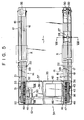
- the massage apparatus is provided with a rectangular base plate 1.
- the base plate 1 is integrally formed from nylon, polypropylene, polyvinyl chloride, urethane or some other synthetic resin, having the configuration mentioned below and a measure of flexibility.
- a number of cavities 2 having a rectangular cross-section are arranged parallel to the direction along the width of the base plate 1.
- the cavitives 2 penetrate the base plate 1 across the same. Namely, the cavities 2 extend from one side face of the base plate 1 to the other. Also, the cavities 2 are arranged at regular intervals in the longitudinal direction of the base plate 1. As seen from Fig.
- the slits 3 extend across the base plate 1.
- the base plate 1 is not limited to the configuration shown in Fig. 3, and may be replaced with a base plate 1' constructed as shown in Fig. 4.
- the base plate'1' is formed by combining the base plate 1 shown in Fig. 3 with two flexible or'rigid reinforcement plates 4 formed of synthetic resin or laminated plywood and a flexible plate 5.
- the reinforcement plates 4, are bonded, or coupled by means of screws not shown, to the whole upper surface of the base plate 1 except for section III of Fig. 2.
- the flexible plate 5 has the same configuration as the section III of the base plate 1, and is coupled to the upper surface of the section III by means of coupling screws 6.
- the coupling screws 6 are arranged only in the central portion of the flexible plate 5.
- the base plate 1' with such an arrangement can be folded at its predetermined folding portion.
- the base plate 1 is mounted with a massage device 10 which will be mentioned later.
- the base plate 1 and the massage device 10 are covered with a covering 11.
- the covering 11 is formed of a cushion portion 12 surrounding the massage device 10 and a wrapping cloth 13.
- the cushion portion 12 is a flexible portion made of an elastic material, such as urethane foam.
- the wrapping cloth 13 is in the form of an enclosure made of canvas, nylon cloth or other cloth with a relatively high wear resistance.
- the massage device 10 is provided with a pair of guide rails 14.
- the guide rails 14 are arranged at a predetermined space on the base plate 1, extending parallel to each other along the longitudinal direction of the base plate 1.
- the guide rails 14 are integrally formed from a synthetic resin and are somewhat flexible. As shown in detail in Fig.
- each guide rail 14 includes an intermediate strip portion 15, upper and lower L-shaped retaining portions 16 which face each other and which protrude upward and downward from one side edge of the intermediate strip portion 15 and extend along the longitudinal direction of the base plate 1, an I-shaped protrusion 17 vertically extending from the other side edge of the intermediate strip potion 15, and two pair of angled projections 18 protruding from the upper and lower surfaces of the central portion of the intermediate strip portion 15 so as to cover part of the same.
- an upper passage 19 surrounded by the intermediate strip portion 15 and the upper parts of the projections 18, and a lower passage 20 surrounded by the intermediate strip portion 15 and the lower parts of the projections 18 are defined at the central portion of the width of each guide rails 14.
- the upper and lower passages 19 and 20 serve as guide passages for traveling belts which will be mentioned later.
- the region between one upper projection 18 and the upper retaining portion 16 above the intermediate strip portion 15 forms a rail groove for the wheels of a carrier which will be mentioned later.
- each guide rail 14 is fixed to the base plate and a unit case which will be mentioned later 1 by means of a plurality of fixing screws 21.
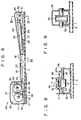
- the other end side of each guide rail 14 is slidably supported by a plurality of support members 22 as shown in Figs. 1, 5 and 7.
- Figs. 1 and 5 only one support member 22 is illustrated for each guide rail 14.
- each support member 22 includes an intermediate strip portion 23 located between the lower surface of the guide rail 14 and the upper surface of the base plate 1 and fixed to the base plate 1 by means of setscrews (not shown), a first holding portion 24 on one side edge of the intermediate strip portion 23 for slidably holding the lower retaining portion 16 of the guide rail 14, and a second holding portion 25 on the other side edge of the intermediate strip potion 23 for slidably holding the protrusion 17 of the guide rail 14.
- each guide rail 14 is bent upward or away from the upper surface of the base plate 1.
- This bent portion 14a of the guide rail 14 is held on a slope frame 26.
- a pitching roll 27 is rotatably supported inside the slope frame 26 at one end portion thereof by means of a support shaft 28.
- the pitching roll 27 projects slightly from the upper surface of the slope frame 26 through an opening 29 in the top wall of the slope frame 26.
- those lower parts of the projections 18 of the guide rail 14 which correspond to the opening 29 of the slope frame 26 are partially cut away.
- a pulley 30 is rotatably supported inside the other end side portion of the slope frame 26 projected from the guide rail 14 by means of a support shaft 31.
- the other end portion of the slope frame 26 is closed by a cap 32.
- a number of slits 33 are formed in that region of each guide rail 14 which corresponds to the predetermined folding portion of the base plate 1 indicated by symbol III in Fig. 2, that is, portion X of Fig. 5.
- These slits 33 are arranged across the width of the guide rails 14 except for the intermediate strip portion 15 thereof. Therefore, the region indicated by symbol X in Fig. 5, like the predetermined folding portion of the base plate 1, is expressly flexible, and the guide rails 14 can be folded in two at the predetermined fold portion or at region X.
- a drive mechanism 34 is mounted on the base plate 1.
- the drive mechanism 34 comprises a drive unit 35 set on the one end portion of the base plate 1 so as to . adjoin the one end of each guide rail 14, and a pair of traveling belts 36 driven by the drive unit 35.
- the drive unit 35 is provided with a unit case 37.
- the unit case 37 stretches between the two guide rails 14.
- a rigid reinforcement plate 38 is attached as required to the lower surface of that portion of the base plate 1 on which the drive unit 35 is mounted.
- a mounting board 39 is housed in the unit case 37.
- the mounting board 39 consists of a level plate portion 40 on the top of the base plate 1, and standing plate portions 41 on both end edges of the level plate portion 40 near the guide rails 14.
- a unit motor 42 Disposed between the two standing plate portions 41 of the mounting board 39 is a unit motor 42 which is a combination of an electric motor and a reducer.
- the unit motor 42 is a reversible motor whose output shaft 43 extends to the outside through one of the standing plate portions 41 of the mounting board 39.
- a first driving gear 44 formed of a spur gear and a first driving pulley 45 are successively mounted on the output shaft 43 of the unit motor 42, located outside the mounting board 39.
- a first driven shaft 46 extends parallel to the output shaft 43 of the unit motor 42. Both end portions of the first drive shaft 46 extend through the standing plate portions 41 of the mounting board 39 to the outside thereof.
- the first driven shaft 46 is rotatably supported between the two standing plate portions 41.
- One end portion of the first driven shaft 46 near the unit moror 42 is successively fitted with a first driven gear 47 in mesh with the first driving gear 44 and a first driven pulley 48 paired with the first driving pulley 45.
- a second driving gear 49 formed of a spur gear and a second driving pulley 50 are successively mounted on the other end portion of the first driven shaft 46, located outside the other standing plate portion 41.
- a second driven shaft 51 parallel to the first driven shaft 46 is rotatably supported on that standing plate portion 41 of the mounting board 39 which rotatably supports the other end portion of the first driven shaft 46.
- the second driven shaft 51 extends to the outside of the standing plate portion 41.
- the second driven shaft 51 is fitted with a second driven gear 52 to mesh with the second driving gear 49, and a second driven pulley 53 which is paired with the second driving pulley 50.
- the gears 44, 47, 49 and 52 are all rotated at the same speed.
- One of the paired traveling belts 36 formed of, e.g., steel, stainless steel on cloth belts for transmitting power is wound around the first driving pulley 45.
- One end of this traveling belt 36 is fixed to the first driving pulley 45.
- one traveling belt 36 is guided from the first driving pulley 45 into the upper passage 19 of the one guide rail 14, travels along the upper passage 19, and is passed around the pulley 30 to change its course about 180°. Then, the traveling belt 36 is passed through the interior of the slope frame 26 and the opening 29 thereof, turns to a somewhat different direction on the pitching roll 27, and is led to the first driven pulley 48 through the lower passage 20 of the guide rail 14.
- the traveling belt 38 is wound around the first driven pulley 48 with its other end fixed thereto.
- the guide rail 14 is illustrated as a mere hollow passage for simplicity.
- Fig. 7 shows how the traveling belt 36 is actually guided through the upper and lower passages 19 and 20 of the guide rail 14.
- the other traveling belt 36 is guided through the other guide rail 14, and passed around the second driving pulley 50 and the second driven pulley 53.
- the drive mechanism 34 when the output shaft 43 of the unit motor 42 is rotated, for example, in the direction of arrow Al in Fig. 6, the first driving pulley 45 rotates to be wound with the traveling belt 36. Since the first driven pulley 48 is rotated in the opposite direction to the first driving pulley 45, the traveling belt 36 is let out from the first driven pulley 48 in proportion to the length of the portion of the belt 36 wound'on the first driving pulley 45. In this case, therefore, the portion of the traveling belt 36 guided through the upper passage 19 of the one guide rail 14 is run in the direction of arrow Bl in Fig. 6.
- the traveling belt 36 guided through the upper passage 19 of the other guide rail 14 is run also in the direction of arrow Bl in synchronism with the traveling belt 36 runnding through the one guide rail 14.
- the carrier 60 is provided with a hollow shaft 61 which extends at right angles to the guide rails 14. Each end portion of the hollow shaft 61 is removably fitted in a fitting hole 63 formed in a support leg 62 on each side. Fig. 7 shows only one side of the structure.
- a support shaft 64 is coaxially passed through the hollow shaft 61. Both end portions of the support shaft 64 are formed into screw portions 65.
- the support shaft 64 is fixed to the support leg 62 by screwing a nut 66 on each screw portion 65.
- a pair of wheels 67 are rotatably attached to the support leg 62 by means of support shafts 68.
- the wheels 67 are fitted in the rail groove 69 of each guide rail 14 so as to be able to travel along the groove 69.
- a substantially T-shaped coupler 70 is attached to the lower portion of the support leg 62.
- both ends of that portion of the coupler 70 which extend along the guide rail 14 are attached individually to the support shafts 68 of the wheels 67.
- the carrier 60 is caused to travel along the rail grooves 69 of the guide rails 14 as the traveling belts 36 run.
- a pair of first sleeves 73 and a pair of second sleeves 74 are alternately mounted on the outer peripheral surface of the hollow shaft 61 of the carrier 60.
- the first and second sleeves 73 and 74 can rotate around the hollow shaft 61, and are restrained from axial movement by spacers 75, as shown in Fig. 7.
- Each first sleeve 73 is fitted with a cylindrical first massage roller 76.
- the massage roller 76 is integrally formed from a relatively hard elastic material, such as rubber or synthetic resin.
- a number of substantially hemispherical massage bumps 77 are circumferentially arranged at regular intervals on the outer peripheral surface of the first massage roller 76.
- the first massage roller 76 is restrained from axial dislocation by stoppers 78 on the first sleeve 73.
- a plurality of axially extending hollow portions 79 is formed in the first massage roller 76 corresponding to the massage bumps 77.
- the massage bumps 77 of the first massage roller 76 can easily be elastically displaced in the radial direction.
- Each second sleeve 74 is also fitted with a second massage roller 80 similar to the first massage roller 76.
- the second massage roller 80 differs from the first massage roller 76 in that its axial length is shorter than that of the first massage roller 76, and that it is penetrated by its hollow portions 79. It is to be understood that the second sleeve 74 is also provided with stoppers 78 similar to those for the first sleeve 73.
- the first and second massage rollers 76 and 80 of each carrier 60 are moved along the pair of guide rails 14.
- the first and second massage rollers 76 and 80 In order to effectively massage the entire body of a user, however, the first and second massage rollers 76 and 80 must be automatically reciprocated along the guide rails 14 within a predetermined range.
- the apparatus according to the first embodiment of the invention is provided with a control unit 90 for automatically reciprocating the traveling belts 36.
- the control unit 90 is housed in the unit case 37 of the dirve mechanism 34, as shown in F ig. 5, and is illustrated in detail in Figs. 13 and 14.
- the control unit 90 is provided with a rotating disk 91.
- the rotating disk 91 is fixed to the first driven shaft 46 of the drive mechanism 34 by means of a setscrew 92.
- First and second spiral guide grooves 93 and 94 of the same configuration are formed on one and the other side faces of the rotating disk 91, respectively.
- a first . step portion 95 and a second step portion 96 shallower than the remaining groove portions are formed in the first and second guide grooves 93 and 94, respectively.
- the first step portion 95 is located at a radial distance Rl from the center of the rotating disk 91, while the second step portion 96 is at a radial distance R2 from the center.
- the radius R1 is greater than the radius R2. This indicates that the first step portion 95 is located father away than the second step portion 96 for several turns of the first guide groove 93.
- a rocking arm 97 is disposed beside the rotating disk 91.
- the rocking arm 97 has a U-shaped cross-sectional shape so as to cover part of the rotating disk 91.
- the lower end portion of the rocking arm 97 is rockably supported on a pair of brackets 98 by means of support shafts 99.
- the brackets 98 are fixedly set on the level plate portion 40 of the mounting board 39.
- a belt-shaped first left spring 100 is attached to one outer side face of the rocking arm 97.
- the first leaf spring 100 extends from the proximal end side of the rocking arm 97 toward its distal end side.
- the lower end portion of the first leaf spring 100 is fixed to the rocking arm 97 by means of a retaining shaft 101.
- a first pin 102 is attached to the upper end portion of the first leaf spring 100.
- the first pin 102 extends to the inside of the rocking arm 97.through one of openings 103 (see Fig. 16) in both the outer side faces of the rocking arm 97, and projects into the first guide groove 93 of the rotating disk 91.
- a second leaf spring 104 is attached to the other outer side face of the rocking arm 97.
- a second pin 105 of the second leaf spring 104 projects into the second guide groove 94 of the rotating disk 97.
- fixtures 106 formed of plate members are fixed to one outer sides face of the rocking arm 97, respectively.
- a first limit switch 107 formed.of a microswitch is attached to one fixture 106.
- a push button 108 of the first limit switch 107 faces the first leaf spring 100 at a given gap.
- a second limit switch 109 is attached to another fixture 106, and a push button 110 of the second limit switch 109 faces the second leaf spring 104 at a given gap.
- the first and second limit switches 107 and 109, and the electric motor section of the unit motor 42 are electrically connected to an electric circuit (not shown).
- This electric circuit is designed so as to reverse the rotating direction of the electric motor section of the unit motor 42 when one of the limit switches 107 and 109 is activated.
- the electric circuit includes a remote switch (not shown) for remotely controlling the drive of the electric motor section of the unit motor 42.
- the control unit 90 When the output shaft 43 of the unit motor 42 is rotated in the direction of arrow Al by operating the remote switch, the pair of traveling belts 36 travels through the interior of their corresponding guide rails 14 in the manner described before. In this case, the traveling direction of the traveling belts 36 passing through the upper passages 19 of the guide rails 14 is the direction indicated by arrow Bl in Fig. 6. As the traveling belts 36 travel in this manner, the rotating disk 91 of the control unit 90 rotates with the first driven shaft 46. In this case, the rotating disk 91 rotates in the direction indicated by arrow Cl in Fig.
- both the first and second pins 102 and 105 of the first and second leaf springs 100 and 104 are located between the first and second step portions 95 and 96 of the first and second guide grooves 93 and 94 with respect to the radial direction of the rotating disk 91, the first pin 102 of the first leaf spring 100 will first run onto the first step portion 95 of the first guide groove 93, as indicated by the imaginary line in Fig. 15, as the rocking arm 97 rocks in the direction of arrow D1 in Fig. 13.
- the first leaf spring 100 of the rocking arm 97 bends backward, as indicated by the imaginary line in Fig. 16, to press the push button 108 of the first limit switch 107, thereby shifting the switch 107.
- the rotation of the output shaft 43 of the unit motor 42 is reversed from the direction of arrow Al to the direction of arrow A2 by the aforementioned electric circuit, so that the traveling belts 36, having so far been running in the direction of arrow Bl through the upper passages 19 of the guide rails 14, start to run in the direction of arrow B2 opposite to the direction of arrow B1.
- the rotating direction of the output shaft 43 of the unit motor 42 is switched from the direction of arrow Al to the direction of arrow A2
- the rotating direction of the rotating disk 91 is changed from the direction of arrow C1 to the direction of arrow C2.
- the rocking direction of the rocking arm 97 is changed from the direction of arrow D1 to the direction of arrow D2.
- the traveling belts 36 running through the upper passages 19 of the guide rails 14 automatically change their courses from the direction of arrow Bl to the direction of arrow B2 or from B2 to Bl. Accordingly, the carriers 60 coupled to the traveling belts 36 and hence the first and second massage rollers 76 and 80 are reciprocated along the guide rails 14.
- the reciprocation stroke of the carriers 60 or the massage rollers 76 and 80 depends on the radial distance of the rotating disk 91 between the first step portion 95 of the first guide groove 94 and the second step portion 96 of the second guide groove 94.
- control unit 90 serves to determine the maximum reciprocation stroke of the carriers 60, part within the maximum reciprocation stroke of the carriers 60 may be restricted by the electric circuit.
- Figs. 17 to 19 there will be described the way the user uses the massage apparatus according to the above-mentioned embodiment.
- the user lies on the massage apparatus.
- the remote switch (not shown) to actuate the unit motor 42
- the massage rollers 76 and 80 will reciprocate along the guide rails 14 while rotating in contact with the inside of the warpping cloth 13.
- the back of the user is massaged by the massage bumps 77 of the massage rollers 76 and 80.
- the massage apparatus with this construction can be folded in two as shown in Fig. 18, since the central portions of the base plate 1 and the guide rials 14.are expressly flexible.
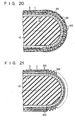
- Fig. 19 shows a cross-sectional view of a fold portion of the massage apparatus.
- each guide rail 14 is fixed to the base plate 1 by means of the fixing screws 21, while the other end side of each guide rail 14 is slidably held over the base plate 1 by means of the support members 22. Accordingly, the guide rails 14 or the whole massage apparatus can be easily be folded without producing any substantial bending stress in the guide rails 14.
- the traveling belts 36 are used as elongated members for power transmission.
- the blets 36 may be replaced with chains or wires.
- the predetermined folding portion of the base plate 1 is formed by coupling a plurality of belt-shaped plate members 120 by means of hinges 121.
- the predetermined folding portion of the base plate 1 consists of a corrugated coupling member 122 made of an elastic material such as synthetic resin. Each end of the coupling member 122 is fixed to the end portion of each corresponding division of the base plate 1 by means of a fitting piece 123.
- the slits 33 are arranged at regular intervals throughout the length of the guide rail 14.
- the guide rail 14 is formed of a flexible material such as polypropylene or rubber, and can be folded without the slits 33.
- the slits 3 are arranged at regular intervals throughout the length of the base plate 1.
- Fig. 25 shows a combination of the guide rail 14 of Fig. 22 and the base plate 1 of Fig. 24, while Fig. 26 shows a combination of the base plate 1 of Fig. 24 and the guide rail 14 of Fig. 23.
- Figs. 27 to 29 show modifications in which the base plate 1 is formed of a flexible material such as polypropylene or rubber, and can be folded without the slits 3.
- Fig. 27 shows a combination of the base plate 1 with this arrangement and the guide rail 14 of Fig. 19
- Fig. 28 shows a combination of the base plate 1 and the guide rail 14 of Fig. 22
- Fig. 29 shows a combination of the base plate 1 and the guide rail 14 of Fig. 23.
- the above description is premised on an assumption that the massage apparatus is folded in two.
- the whole massage apparatus may be folded in the manner shown in Fig. 30 or 31 by providing each of the base plate 1 and the guide rail 14 with two or more predetermined fold portions or by making the base plate 1 and the guide rail 14 foldable at any position in the aforementioned manner.
- a base to be used in place of the base plate 1 includes two flexible or rigid plates 130 arranged so as to support the whole length of each guide rail 14 except the central portion thereof, and a plurality of auxiliary crosspieces 131 arranged at regular intervals along the guide rails 14 between the plates 130.
- the massage apparatus may be folded in the manner shown in Fig. 34 or 35, for example.
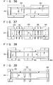
- Fig. 36 shows a modification in which the base is formed of the two plates 130 only
- Fig. 37 shows an example in which the base includes three plates 130 and the auxiliary cross-piece 131 arranged between the plates 130.
- Fig. 39 shows a base which is formed of two plates 132 at both ends of each guide rail 14 and two auxiliary crosspieces 131 arranged between the plates 132. With the use of the bases shown in Figs. 37 to 39, the base can be folded at a plurality of positions.
- Figs. 40 and 41 show a base which comprises two rigid plates 130 and a flexible plate 200 disposed between the plates 130, the flexible plate 20 made of polypropylen, for example.
- the base may be provided as required, and is not an essential member.
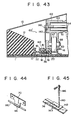
- a first modification of the carriers 60 With a carrier 60' according to the first modification, the support leg 62 and the traveling belt 36 are not coupled directly by the coupler 70, and a wire 140 is used in aid of the coupler 70.
- the wire 140 is slidably passed through a pipe portion 141 which is formed by bending the lower end portion of the coupler 70.
- Each end side of the wire 140 passed through the pipe portion 141 of the coupler 70 extends through the upper passage 19 of the guide rail 14, passes through a pair of pipes 143 fixed to the traveling belt 36 by means of a mounting plate 142, as shown in Fig. 45, and is then bent upward.
- Both ends of the wire 140 are attached to a mounting plate 145 on the support leg 62 with the aid of metal fittings 146 and a screw.
- the wire 140 forms a triangle with its base extending along the guide rail 14, as shown in Fig. 42.
- the wheels 67 are attached to the support leg 62 so as to project outward from the support leg 62, as shown in Fig. 42.
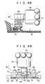
- the massage apparatus can easily be folded even at the position where the carrier 60' is located. If the massage apparatus is folded at the location of the carrier 60', the base of the substantially triangular wire 140 is bent as shown in Fig. 46. As the wire 140 is bent in this manner, the carrier 60' is moved in the direction of arrow F in Fig. 46, so that the massage apparatus can easily be folded without being substantially hindered by the carrier 60'. If the distance between the pair of pipes 143 before the holding of the massage apparatus is w2, as shown in Fig.
- the distance wl between the pipes 143 after the folding is shorter than the distance w2 by a length for the flexure of the base of the wire 140.
- a second modification of the carrier 60 In a carrier 60" according to the second modification, the support leg 62 is provided with a pair of first links 150 which are rockably mounted at the upper end portion thereof on each hollow shaft 61. The lower end portions of the first links 150 spread away from each other, and are rotatably fitted with the wheels 67 by means of the support shafts 68.
- One end of each of a pair of second links 151 is rockably coupled to the support shaft 68 of each corresponding wheel 67.
- the other ends of the second links 151 are rockably coupled to a first coupler 152 by means of a pin 153.
- the first coupler 152 is fixed to the traveling belt 36 guided through the upper passage 19 of the guide rail 14.
- Second couplers 154 are attached to the support shafts 68 of their corresponding wheels 67.
- the support shafts 68 of the wheels 67 are passed through guide holes 155 in their corresponding second couplers 154, and the second couplers 154 are fixed to the traveling belt 36 in the guide rail 14 in the same manner as the first coupler 152.
- the carrier 60" of the second modification can provide the same function and effect as those of the carrier 60' of the first modification.
- numeral 156 designates stoppers attached to the second links 151.
- the stoppers 156 are adapted to abut against the side faces of the first coupler 152, thereby preventing the second links 151 from rocking further donward.
Landscapes
- Health & Medical Sciences (AREA)
- Epidemiology (AREA)
- Pain & Pain Management (AREA)
- Physical Education & Sports Medicine (AREA)
- Rehabilitation Therapy (AREA)
- Life Sciences & Earth Sciences (AREA)
- Animal Behavior & Ethology (AREA)
- General Health & Medical Sciences (AREA)
- Public Health (AREA)
- Veterinary Medicine (AREA)
- Massaging Devices (AREA)
Priority Applications (1)
| Application Number | Priority Date | Filing Date | Title |
|---|---|---|---|
| AT84104081T ATE37785T1 (de) | 1983-04-11 | 1984-04-11 | Massagegeraet. |
Applications Claiming Priority (4)
| Application Number | Priority Date | Filing Date | Title |
|---|---|---|---|
| JP58063339A JPS59189849A (ja) | 1983-04-11 | 1983-04-11 | マツサ−ジ装置 |
| JP63339/83 | 1983-04-11 | ||
| JP194867/83 | 1983-12-20 | ||
| JP19486783U JPS60102018U (ja) | 1983-12-20 | 1983-12-20 | マツサ−ジ装置 |
Publications (3)
| Publication Number | Publication Date |
|---|---|
| EP0121945A2 true EP0121945A2 (de) | 1984-10-17 |
| EP0121945A3 EP0121945A3 (en) | 1985-12-04 |
| EP0121945B1 EP0121945B1 (de) | 1988-10-12 |
Family
ID=26404441
Family Applications (1)
| Application Number | Title | Priority Date | Filing Date |
|---|---|---|---|
| EP84104081A Expired EP0121945B1 (de) | 1983-04-11 | 1984-04-11 | Massagegerät |
Country Status (6)
| Country | Link |
|---|---|
| EP (1) | EP0121945B1 (de) |
| AT (1) | ATE37785T1 (de) |
| AU (1) | AU550145B2 (de) |
| DE (1) | DE3474508D1 (de) |
| HK (1) | HK98591A (de) |
| SG (1) | SG82591G (de) |
Family Cites Families (2)
| Publication number | Priority date | Publication date | Assignee | Title |
|---|---|---|---|---|
| US4373516A (en) * | 1979-12-27 | 1983-02-15 | France Bed Co., Ltd. | Apparatus for chiropractic therapy and massage |
| DE3263589D1 (en) * | 1981-02-17 | 1985-06-27 | France Bed Co | Apparatus for chiropractic therapy and massage |
-
1984
- 1984-04-03 AU AU26380/84A patent/AU550145B2/en not_active Expired
- 1984-04-11 AT AT84104081T patent/ATE37785T1/de active
- 1984-04-11 DE DE8484104081T patent/DE3474508D1/de not_active Expired
- 1984-04-11 EP EP84104081A patent/EP0121945B1/de not_active Expired
-
1991
- 1991-10-08 SG SG825/91A patent/SG82591G/en unknown
- 1991-12-05 HK HK985/91A patent/HK98591A/en not_active IP Right Cessation
Also Published As
| Publication number | Publication date |
|---|---|
| SG82591G (en) | 1991-11-22 |
| HK98591A (en) | 1991-12-13 |
| ATE37785T1 (de) | 1988-10-15 |
| AU2638084A (en) | 1984-10-18 |
| AU550145B2 (en) | 1986-03-06 |
| EP0121945B1 (de) | 1988-10-12 |
| DE3474508D1 (en) | 1988-11-17 |
| EP0121945A3 (en) | 1985-12-04 |
Similar Documents
| Publication | Publication Date | Title |
|---|---|---|
| US4656998A (en) | Foldable massage bed with reciprocating rollers | |
| US4947833A (en) | Bed-type roller massaging machine | |
| US4662362A (en) | Massage apparatus | |
| CA2171095C (en) | Massaging apparatus | |
| US4373516A (en) | Apparatus for chiropractic therapy and massage | |
| JP2001037836A (ja) | 電動ローラーマッサージ用ユニット式ローラー駆動装置、及びこれを設置した電動ローラーマッサージ具 | |
| EP0121945B1 (de) | Massagegerät | |
| JP2003180780A (ja) | マット型全身マッサージ機 | |
| US4960110A (en) | Bed-type massaging apparatus | |
| KR860001800B1 (ko) | 맛사아지 장치 | |
| US4170989A (en) | Massaging apparatus | |
| JP3694610B2 (ja) | マッサージ装置 | |
| JP3582095B2 (ja) | マッサージ装置 | |
| KR840001977B1 (ko) | 지압장치 | |
| JPH0420434Y2 (de) | ||
| JPH0340284Y2 (de) | ||
| JPH08154991A (ja) | マッサージ装置 | |
| JPH0420435Y2 (de) | ||
| JPH0420433Y2 (de) | ||
| JPS6311902B2 (de) | ||
| JP3065861B2 (ja) | マッサージ装置 | |
| JPH0130179Y2 (de) | ||
| JPS6311900B2 (de) | ||
| JP4511329B2 (ja) | マッサージ装置 | |
| JPH0122663Y2 (de) |
Legal Events
| Date | Code | Title | Description |
|---|---|---|---|
| PUAI | Public reference made under article 153(3) epc to a published international application that has entered the european phase |
Free format text: ORIGINAL CODE: 0009012 |
|
| 17P | Request for examination filed |
Effective date: 19840615 |
|
| AK | Designated contracting states |
Designated state(s): AT BE CH DE FR GB IT LI LU NL SE |
|
| PUAL | Search report despatched |
Free format text: ORIGINAL CODE: 0009013 |
|
| AK | Designated contracting states |
Designated state(s): AT BE CH DE FR GB IT LI LU NL SE |
|
| 17Q | First examination report despatched |
Effective date: 19870421 |
|
| GRAA | (expected) grant |
Free format text: ORIGINAL CODE: 0009210 |
|
| AK | Designated contracting states |
Kind code of ref document: B1 Designated state(s): AT BE CH DE FR GB IT LI LU NL SE |
|
| PG25 | Lapsed in a contracting state [announced via postgrant information from national office to epo] |
Ref country code: AT Effective date: 19881012 |
|
| REF | Corresponds to: |
Ref document number: 37785 Country of ref document: AT Date of ref document: 19881015 Kind code of ref document: T |
|
| ITF | It: translation for a ep patent filed | ||
| REF | Corresponds to: |
Ref document number: 3474508 Country of ref document: DE Date of ref document: 19881117 |
|
| ET | Fr: translation filed | ||
| PG25 | Lapsed in a contracting state [announced via postgrant information from national office to epo] |
Ref country code: LU Free format text: LAPSE BECAUSE OF NON-PAYMENT OF DUE FEES Effective date: 19890430 |
|
| PLBE | No opposition filed within time limit |
Free format text: ORIGINAL CODE: 0009261 |
|
| STAA | Information on the status of an ep patent application or granted ep patent |
Free format text: STATUS: NO OPPOSITION FILED WITHIN TIME LIMIT |
|
| 26N | No opposition filed | ||
| ITTA | It: last paid annual fee | ||
| EAL | Se: european patent in force in sweden |
Ref document number: 84104081.9 |
|
| REG | Reference to a national code |
Ref country code: GB Ref legal event code: IF02 |
|
| PGFP | Annual fee paid to national office [announced via postgrant information from national office to epo] |
Ref country code: CH Payment date: 20030311 Year of fee payment: 20 |
|
| PGFP | Annual fee paid to national office [announced via postgrant information from national office to epo] |
Ref country code: FR Payment date: 20030314 Year of fee payment: 20 |
|
| PGFP | Annual fee paid to national office [announced via postgrant information from national office to epo] |
Ref country code: BE Payment date: 20030325 Year of fee payment: 20 |
|
| PGFP | Annual fee paid to national office [announced via postgrant information from national office to epo] |
Ref country code: GB Payment date: 20030409 Year of fee payment: 20 |
|
| PGFP | Annual fee paid to national office [announced via postgrant information from national office to epo] |
Ref country code: SE Payment date: 20030416 Year of fee payment: 20 |
|
| PGFP | Annual fee paid to national office [announced via postgrant information from national office to epo] |
Ref country code: DE Payment date: 20030422 Year of fee payment: 20 |
|
| PGFP | Annual fee paid to national office [announced via postgrant information from national office to epo] |
Ref country code: NL Payment date: 20030428 Year of fee payment: 20 |
|
| PG25 | Lapsed in a contracting state [announced via postgrant information from national office to epo] |
Ref country code: LI Free format text: LAPSE BECAUSE OF EXPIRATION OF PROTECTION Effective date: 20040410 Ref country code: GB Free format text: LAPSE BECAUSE OF EXPIRATION OF PROTECTION Effective date: 20040410 Ref country code: CH Free format text: LAPSE BECAUSE OF EXPIRATION OF PROTECTION Effective date: 20040410 |
|
| PG25 | Lapsed in a contracting state [announced via postgrant information from national office to epo] |
Ref country code: NL Free format text: LAPSE BECAUSE OF EXPIRATION OF PROTECTION Effective date: 20040411 |
|
| BE20 | Be: patent expired |
Owner name: *FRANCE BED CY LTD Effective date: 20040411 |
|
| REG | Reference to a national code |
Ref country code: CH Ref legal event code: PL |
|
| REG | Reference to a national code |
Ref country code: GB Ref legal event code: PE20 |
|
| EUG | Se: european patent has lapsed | ||
| NLV7 | Nl: ceased due to reaching the maximum lifetime of a patent |
Effective date: 20040411 |