EP0121955B1 - Vorrichtung zum Erkennen von Dokumenten mittels modulierten reflektierten Lichtes - Google Patents
Vorrichtung zum Erkennen von Dokumenten mittels modulierten reflektierten Lichtes Download PDFInfo
- Publication number
- EP0121955B1 EP0121955B1 EP84200263A EP84200263A EP0121955B1 EP 0121955 B1 EP0121955 B1 EP 0121955B1 EP 84200263 A EP84200263 A EP 84200263A EP 84200263 A EP84200263 A EP 84200263A EP 0121955 B1 EP0121955 B1 EP 0121955B1
- Authority
- EP
- European Patent Office
- Prior art keywords
- light
- signal
- flat
- output signals
- path
- Prior art date
- Legal status (The legal status is an assumption and is not a legal conclusion. Google has not performed a legal analysis and makes no representation as to the accuracy of the status listed.)
- Expired
Links
- 230000003287 optical effect Effects 0.000 claims abstract description 6
- 241000826860 Trapezium Species 0.000 claims abstract description 4
- 238000000034 method Methods 0.000 claims description 3
- 230000015654 memory Effects 0.000 description 6
- 239000000872 buffer Substances 0.000 description 4
- 238000002310 reflectometry Methods 0.000 description 3
- 101001106432 Homo sapiens Rod outer segment membrane protein 1 Proteins 0.000 description 2
- 101150065817 ROM2 gene Proteins 0.000 description 2
- 102100021424 Rod outer segment membrane protein 1 Human genes 0.000 description 2
- 101100322582 Streptomyces coelicolor (strain ATCC BAA-471 / A3(2) / M145) add1 gene Proteins 0.000 description 2
- 239000000758 substrate Substances 0.000 description 2
- 102100034033 Alpha-adducin Human genes 0.000 description 1
- 102100024348 Beta-adducin Human genes 0.000 description 1
- 101150007692 DOA4 gene Proteins 0.000 description 1
- 101000799076 Homo sapiens Alpha-adducin Proteins 0.000 description 1
- 101000689619 Homo sapiens Beta-adducin Proteins 0.000 description 1
- 101000629598 Rattus norvegicus Sterol regulatory element-binding protein 1 Proteins 0.000 description 1
- 101100434411 Saccharomyces cerevisiae (strain ATCC 204508 / S288c) ADH1 gene Proteins 0.000 description 1
- 101100387924 Saccharomyces cerevisiae (strain ATCC 204508 / S288c) DOS2 gene Proteins 0.000 description 1
- 101100523544 Schizosaccharomyces pombe (strain 972 / ATCC 24843) raf1 gene Proteins 0.000 description 1
- 101100467517 Schizosaccharomyces pombe (strain 972 / ATCC 24843) raf2 gene Proteins 0.000 description 1
- 230000001154 acute effect Effects 0.000 description 1
- 101150102866 adc1 gene Proteins 0.000 description 1
- 101150042711 adc2 gene Proteins 0.000 description 1
- 230000005540 biological transmission Effects 0.000 description 1
- 230000002596 correlated effect Effects 0.000 description 1
- 238000010586 diagram Methods 0.000 description 1
- 230000000694 effects Effects 0.000 description 1
- 230000031700 light absorption Effects 0.000 description 1
- 230000000630 rising effect Effects 0.000 description 1
- 230000003746 surface roughness Effects 0.000 description 1
- 238000012876 topography Methods 0.000 description 1
Images

Classifications
-
- G—PHYSICS
- G07—CHECKING-DEVICES
- G07D—HANDLING OF COINS OR VALUABLE PAPERS, e.g. TESTING, SORTING BY DENOMINATIONS, COUNTING, DISPENSING, CHANGING OR DEPOSITING
- G07D7/00—Testing specially adapted to determine the identity or genuineness of valuable papers or for segregating those which are unacceptable, e.g. banknotes that are alien to a currency
- G07D7/06—Testing specially adapted to determine the identity or genuineness of valuable papers or for segregating those which are unacceptable, e.g. banknotes that are alien to a currency using wave or particle radiation
- G07D7/12—Visible light, infrared or ultraviolet radiation
- G07D7/121—Apparatus characterised by sensor details
-
- G—PHYSICS
- G01—MEASURING; TESTING
- G01B—MEASURING LENGTH, THICKNESS OR SIMILAR LINEAR DIMENSIONS; MEASURING ANGLES; MEASURING AREAS; MEASURING IRREGULARITIES OF SURFACES OR CONTOURS
- G01B11/00—Measuring arrangements characterised by the use of optical techniques
- G01B11/30—Measuring arrangements characterised by the use of optical techniques for measuring roughness or irregularity of surfaces
- G01B11/303—Measuring arrangements characterised by the use of optical techniques for measuring roughness or irregularity of surfaces using photoelectric detection means
-
- G—PHYSICS
- G07—CHECKING-DEVICES
- G07D—HANDLING OF COINS OR VALUABLE PAPERS, e.g. TESTING, SORTING BY DENOMINATIONS, COUNTING, DISPENSING, CHANGING OR DEPOSITING
- G07D7/00—Testing specially adapted to determine the identity or genuineness of valuable papers or for segregating those which are unacceptable, e.g. banknotes that are alien to a currency
- G07D7/06—Testing specially adapted to determine the identity or genuineness of valuable papers or for segregating those which are unacceptable, e.g. banknotes that are alien to a currency using wave or particle radiation
- G07D7/12—Visible light, infrared or ultraviolet radiation
-
- G—PHYSICS
- G07—CHECKING-DEVICES
- G07D—HANDLING OF COINS OR VALUABLE PAPERS, e.g. TESTING, SORTING BY DENOMINATIONS, COUNTING, DISPENSING, CHANGING OR DEPOSITING
- G07D7/00—Testing specially adapted to determine the identity or genuineness of valuable papers or for segregating those which are unacceptable, e.g. banknotes that are alien to a currency
- G07D7/20—Testing patterns thereon
Definitions
- the invention relates to an apparatus for document recognition comprising a conveyor means for continuous conveyance of documents being oriented in a predetermined direction along a predetermined path, a light source, an optical system for focussing a light beam from the light source onto a predetermined location in a flat portion of said path, two light detectors each of which being directed to said predetermined location, and a signal processing means for the light detector output signals.
- Such an apparatus is known from patent specification US-A-3 753 617.
- the known apparatus is designed for document recognition from a certain surface roughness.
- one light detector is arranged for sensing diffused light being directed along the normal and the other light detector is arranged for sensing at the angle of incidence reflected light obliquely incident from the light source.
- the signal processing means of the known apparatus the output signals of the two detectors are correlated. The result of this correlation is the basis for a decision as to recognition of a document.
- a surface analyser capable of extracting information relating to the topography of a travelling surface, in particular the geometry and reflectivity, e.g. roughness and dirt of a paper web.
- a light beam is incident substantially perpendicularly onto the travelling surface and two light detectors are directed to said surface at an angle of 20-70° to the normal, whereby the principal axis of each of the light detectors are arranged in a plane perpendicular to said surface and parallel to the direction of conveyance.
- a signal processing means processes the output signals of the light detectors to make up a difference signal and a sum signal, the sum signal indicating only changes in reflectivity and the difference signal indicating only geometrical changes.
- an apparatus according to the first part of claim 1 is characterized in that said light beam is incident at least substantially perpendicularly onto the predetermined location in said flat path portion and that the light detectors are directed to said flat path portion at an angle of at least 50° to the normal, the principal axis of each of the light detectors being arranged in a plane perpendicular to said flat path portion and parallel to the direction of conveyance, and in that the said processing means processes the output signals of the light detectors to make up a quotient signal and a sum signal, and then compares the two signals to each other.
- the apparatus according to the invention eliminates changes in reflectivity caused by dirt on documents and also eliminates changes in light intensity of the source by making up a quotient signal.
- the apparatus according to the invention is used for recognizing documents from a line pattern in intaglio printing thereon when transferring the documents such that the direction of transfer is intersecting the pattern lines at a considerable angle.
- the apparatus according to the invention is further characterized in that underneath the said flat portion in said path a light diffuing member is arranged in the form of a transparent and plano-parallel plate, its cross-section according to the direction of conveyance and perpendicular to said flat path portion being an isosceles trapezium having its legs intersecting the principal axes of the respective light detectors, wherein the short face of said light diffusing member is frosted, the light beam being incident perpendicularly onto the long face of said light diffusing member.
- a further measure contributing to the automatic operation of the apparatus is the presence of an edge detector in the said flat path portion, said signal processing means being arranged for control by an output signal of the edge detector in order to discriminate, when prompted by the edge detector output signal, detector output signals as effected by said light diffusing member, and to utilize said detector output signals for automatic signal level adjustment.
- the apparatus according to the invention enables the recognition of very fine intaglio line patterns when the light source comprises a laser.
- the apparatus according to the invention is uniquely suitable for digital processing the light detector output signals to produce a real time decision as to recognition of a document, whereby the signal processing means is implemented as an interface with the external data bus of a digital computer while maintaining a transfer velocity of the documents in the flat path portion amounting to 4 meters per second, for example.
- a light source 1 illuminates a narrow strip in the flat path portion 13 of the conveyor means through a cylinder lens 2.
- the narrow strip is oriented perpendicularly to the direction of conveyance of the conveyor (and perpendicularly to the plane of the drawing).
- light detectors 4, 14 are arranged symmetrically at an angle of 60° to the normal along which light beam 11 is incident onto flat path portion 13.
- An optical system with an objective 3 collects diffused light from the flat path portion 13 wherein a document to be tested is present or not. When no light diffusing document is present in said flat path portion at the spot where the light beam is incident, diffused light is collected from a light diffusing member 8.
- the light diffusing member is a transparent and plano-parallel plate, its cross-section in the direction of conveyance of the documents in the flat path portion 13, being shaped like an isosceles trapezium.
- the dimensions of the plate and the distance between plate and conveyor path have been selected such that light being reflected internally at the bevelled edges, is incident into light detector 4 through optical system 3.
- Light beam 11 incident from the light source into light diffusing member 8, is diffused at frosted short face 15 of plate 8. Both acute angles in the trapezium- shaped cross-section are angles of 75°, for example.
- a gray filter 7 may be arranged in the path of light beam 11 for an overall adjustment of its intensity.
- a light filter 5 with limited transmission band may be arranged to bar undesired light from entering the respective light detector.
- the apparatus comprises an edge detector including a light switch 9 and a reflector 10.
- the instant at which light switch 9 detects an interruption, is determinant for automatic signal processing in the signal processing means. This instant discriminates between a calibration by means of detected diffused light from light diffusing member 8 and a registration for document recognition, for example.
- the fineness of the line pattern and the width of the narrow illuminated strip are attuned to each other to create good working conditions for the apparatus.
- the width of the narrow illuminated strip is advantageously smaller than the effective width of an ink line and that is the reason why a laser is used as light source in the apparatus.
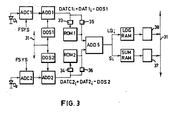
- the signal processing means is diagrammatically shown in Fig. 3.
- the output signals produced in the light sensitive diodes D1 and D2 respectively, are respectively fed to an A/D converter ADC1, ADC2 controlled by a clock signal FSYS.
- each of the read-only memories ROM1, ROM2 feeds a sample DATC1,, DATC2,, respectively, into adder ADD5 and memory LOGRAM.
- Read-only memories ROM1 and ROM2 calculate the values LOG DATC1, and -LOG DATC2,, respectively. Consequently for each set of samples a value LQ, representing the quotient signal, gets into memory LOGRAM.
- the samples are directly fed through buffers 35, 36 respectively, into adder ADD5 for calculating sum S j representing the sum signal, and then into a memory SUMRAM.
- the memories LOGRAM and SUMRAM are being read through buffers 37, 38, respectively, into data bus 31 for further processing in the computer.
- FIG. 3 actually shows the light detectors and their interface with a processor.
- a FSYS-clock pulse repetition time of 2 us a transfer velocity of the documents of 4 meters per second or 20 documents per second, and a line pattern on each document which can be fitted in a time window in the order of 2 ms, to recognize this line pattern by its relief.
Landscapes
- Physics & Mathematics (AREA)
- General Physics & Mathematics (AREA)
- Health & Medical Sciences (AREA)
- General Health & Medical Sciences (AREA)
- Toxicology (AREA)
- Length Measuring Devices By Optical Means (AREA)
- Inspection Of Paper Currency And Valuable Securities (AREA)
- Controlling Sheets Or Webs (AREA)
- Character Input (AREA)
Claims (4)
Priority Applications (1)
| Application Number | Priority Date | Filing Date | Title |
|---|---|---|---|
| AT84200263T ATE26893T1 (de) | 1983-03-11 | 1984-02-24 | Vorrichtung zum erkennen von dokumenten mittels modulierten reflektierten lichtes. |
Applications Claiming Priority (2)
| Application Number | Priority Date | Filing Date | Title |
|---|---|---|---|
| NL8300892 | 1983-03-11 | ||
| NL8300892A NL8300892A (nl) | 1983-03-11 | 1983-03-11 | Inrichting voor het herkennen van documenten aan gemoduleerd geremitteerd licht. |
Publications (2)
| Publication Number | Publication Date |
|---|---|
| EP0121955A1 EP0121955A1 (de) | 1984-10-17 |
| EP0121955B1 true EP0121955B1 (de) | 1987-04-29 |
Family
ID=19841538
Family Applications (1)
| Application Number | Title | Priority Date | Filing Date |
|---|---|---|---|
| EP84200263A Expired EP0121955B1 (de) | 1983-03-11 | 1984-02-24 | Vorrichtung zum Erkennen von Dokumenten mittels modulierten reflektierten Lichtes |
Country Status (4)
| Country | Link |
|---|---|
| EP (1) | EP0121955B1 (de) |
| AT (1) | ATE26893T1 (de) |
| DE (1) | DE3463420D1 (de) |
| NL (1) | NL8300892A (de) |
Families Citing this family (4)
| Publication number | Priority date | Publication date | Assignee | Title |
|---|---|---|---|---|
| US4881268A (en) * | 1986-06-17 | 1989-11-14 | Laurel Bank Machines Co., Ltd. | Paper money discriminator |
| US5199543A (en) * | 1990-08-22 | 1993-04-06 | Oki Electric Industry Co., Ltd. | Apparatus for and method of discriminating bill |
| EP0622762B1 (de) * | 1993-04-27 | 1998-07-01 | The Furukawa Electric Co., Ltd. | Vorrichtung zum Nachweis von Fluoreszenz |
| NL9401796A (nl) * | 1994-10-28 | 1996-06-03 | Tno | Documentherkenningsinrichting. |
Family Cites Families (6)
| Publication number | Priority date | Publication date | Assignee | Title |
|---|---|---|---|---|
| CH537064A (de) * | 1971-02-26 | 1973-05-15 | Gretag Ag | Verfahren und Vorrichtung zur automatischen Echtheitsprüfung von graphischen Vorlagen |
| NL7410463A (en) * | 1974-08-05 | 1976-02-09 | Tno | Document recognition system with relief of characteristic patter - has pick ups for modulated monochromatic light beam one along normal other at angle |
| AT342901B (de) * | 1976-04-28 | 1978-04-25 | Aral Austria Gmbh | Vorrichtung zur prufung von dokumenten |
| US4092068A (en) * | 1976-05-05 | 1978-05-30 | Domtar Inc. | Surface sensor |
| US4146330A (en) * | 1977-12-01 | 1979-03-27 | General Electric Company | Optical method and apparatus for surface roughness evaluation |
| CA1089551A (en) * | 1978-06-27 | 1980-11-11 | John M. Lucas | Graininess sensor |
-
1983
- 1983-03-11 NL NL8300892A patent/NL8300892A/nl not_active Application Discontinuation
-
1984
- 1984-02-24 EP EP84200263A patent/EP0121955B1/de not_active Expired
- 1984-02-24 DE DE8484200263T patent/DE3463420D1/de not_active Expired
- 1984-02-24 AT AT84200263T patent/ATE26893T1/de not_active IP Right Cessation
Also Published As
| Publication number | Publication date |
|---|---|
| ATE26893T1 (de) | 1987-05-15 |
| EP0121955A1 (de) | 1984-10-17 |
| DE3463420D1 (en) | 1987-06-04 |
| NL8300892A (nl) | 1984-10-01 |
Similar Documents
| Publication | Publication Date | Title |
|---|---|---|
| US4468120A (en) | Foreign substance inspecting apparatus | |
| US6323954B1 (en) | Process and device for the detection or determination of the position of edges | |
| US5576831A (en) | Wafer alignment sensor | |
| EP0257749A1 (de) | Verfahren und Vorrichtung zur Messung der Streureflexion einer Oberfläche | |
| AU607280B2 (en) | Optical hole seeking apparatus | |
| EP0798669B1 (de) | Apparat zum Unterscheiden von Münzen | |
| EP0315697A4 (en) | Discriminative flaw detector for light-transmissive sheet material | |
| EP1111551A2 (de) | Münzprüfvorrichtung | |
| JP2833908B2 (ja) | 露光装置における位置決め装置 | |
| US4579453A (en) | Method and apparatus for detecting a mark position | |
| EP0121955A1 (de) | Vorrichtung zum Erkennen von Dokumenten mittels modulierten reflektierten Lichtes | |
| EP0098607A2 (de) | Bild eines Fingerabdruckes | |
| EP0018505A2 (de) | Apparat zur Überwachung des Zustandes von Banknoten | |
| US6326606B2 (en) | Method and apparatus for checking shape | |
| JPH1063913A (ja) | 良否判別装置 | |
| JPH1063914A (ja) | 紙葉類検査装置 | |
| JPH0961113A (ja) | ラベル位置検出装置 | |
| JPS60147602A (ja) | マ−クセンサ | |
| JP3012128B2 (ja) | 硬貨判別装置 | |
| EP1164369A2 (de) | Optisches Lesegerät und optisches Leseverfahren | |
| JP3218726B2 (ja) | 異物検査装置 | |
| JPH0643969B2 (ja) | シ−ト状物の欠陥検出方法 | |
| JPH1047928A (ja) | 光学式外形計測装置 | |
| JPH10227617A (ja) | 微小線幅測定方法及び微小線幅測定装置 | |
| JPS6315143A (ja) | 面状体の欠陥検出方法 |
Legal Events
| Date | Code | Title | Description |
|---|---|---|---|
| PUAI | Public reference made under article 153(3) epc to a published international application that has entered the european phase |
Free format text: ORIGINAL CODE: 0009012 |
|
| AK | Designated contracting states |
Designated state(s): AT BE CH DE FR GB IT LI LU NL SE |
|
| 17P | Request for examination filed |
Effective date: 19840808 |
|
| ITF | It: translation for a ep patent filed | ||
| GRAA | (expected) grant |
Free format text: ORIGINAL CODE: 0009210 |
|
| AK | Designated contracting states |
Kind code of ref document: B1 Designated state(s): AT BE CH DE FR GB IT LI LU NL SE |
|
| REF | Corresponds to: |
Ref document number: 26893 Country of ref document: AT Date of ref document: 19870515 Kind code of ref document: T |
|
| REF | Corresponds to: |
Ref document number: 3463420 Country of ref document: DE Date of ref document: 19870604 |
|
| ET | Fr: translation filed | ||
| PLBE | No opposition filed within time limit |
Free format text: ORIGINAL CODE: 0009261 |
|
| STAA | Information on the status of an ep patent application or granted ep patent |
Free format text: STATUS: NO OPPOSITION FILED WITHIN TIME LIMIT |
|
| 26N | No opposition filed | ||
| ITTA | It: last paid annual fee | ||
| EPTA | Lu: last paid annual fee | ||
| PGFP | Annual fee paid to national office [announced via postgrant information from national office to epo] |
Ref country code: SE Payment date: 19950126 Year of fee payment: 12 |
|
| PGFP | Annual fee paid to national office [announced via postgrant information from national office to epo] |
Ref country code: FR Payment date: 19950127 Year of fee payment: 12 |
|
| EAL | Se: european patent in force in sweden |
Ref document number: 84200263.6 |
|
| PGFP | Annual fee paid to national office [announced via postgrant information from national office to epo] |
Ref country code: LU Payment date: 19950201 Year of fee payment: 12 |
|
| PGFP | Annual fee paid to national office [announced via postgrant information from national office to epo] |
Ref country code: GB Payment date: 19950214 Year of fee payment: 12 |
|
| PGFP | Annual fee paid to national office [announced via postgrant information from national office to epo] |
Ref country code: AT Payment date: 19950222 Year of fee payment: 12 |
|
| PGFP | Annual fee paid to national office [announced via postgrant information from national office to epo] |
Ref country code: DE Payment date: 19950227 Year of fee payment: 12 |
|
| PGFP | Annual fee paid to national office [announced via postgrant information from national office to epo] |
Ref country code: NL Payment date: 19950228 Year of fee payment: 12 |
|
| PGFP | Annual fee paid to national office [announced via postgrant information from national office to epo] |
Ref country code: BE Payment date: 19950301 Year of fee payment: 12 |
|
| PGFP | Annual fee paid to national office [announced via postgrant information from national office to epo] |
Ref country code: CH Payment date: 19950308 Year of fee payment: 12 |
|
| PG25 | Lapsed in a contracting state [announced via postgrant information from national office to epo] |
Ref country code: LU Free format text: LAPSE BECAUSE OF NON-PAYMENT OF DUE FEES Effective date: 19960224 Ref country code: GB Effective date: 19960224 Ref country code: AT Effective date: 19960224 |
|
| PG25 | Lapsed in a contracting state [announced via postgrant information from national office to epo] |
Ref country code: SE Effective date: 19960225 |
|
| PG25 | Lapsed in a contracting state [announced via postgrant information from national office to epo] |
Ref country code: BE Effective date: 19960228 |
|
| PG25 | Lapsed in a contracting state [announced via postgrant information from national office to epo] |
Ref country code: LI Effective date: 19960229 Ref country code: CH Effective date: 19960229 |
|
| BERE | Be: lapsed |
Owner name: DE NEDERLANDSCHE BANK N.V. Effective date: 19960228 |
|
| PG25 | Lapsed in a contracting state [announced via postgrant information from national office to epo] |
Ref country code: NL Effective date: 19960901 |
|
| REG | Reference to a national code |
Ref country code: CH Ref legal event code: PL |
|
| GBPC | Gb: european patent ceased through non-payment of renewal fee |
Effective date: 19960224 |
|
| PG25 | Lapsed in a contracting state [announced via postgrant information from national office to epo] |
Ref country code: FR Effective date: 19961031 |
|
| NLV4 | Nl: lapsed or anulled due to non-payment of the annual fee |
Effective date: 19960901 |
|
| PG25 | Lapsed in a contracting state [announced via postgrant information from national office to epo] |
Ref country code: DE Effective date: 19961101 |
|
| REG | Reference to a national code |
Ref country code: FR Ref legal event code: ST |