EP0121967B1 - Transmissions de télévision - Google Patents
Transmissions de télévision Download PDFInfo
- Publication number
- EP0121967B1 EP0121967B1 EP84200336A EP84200336A EP0121967B1 EP 0121967 B1 EP0121967 B1 EP 0121967B1 EP 84200336 A EP84200336 A EP 84200336A EP 84200336 A EP84200336 A EP 84200336A EP 0121967 B1 EP0121967 B1 EP 0121967B1
- Authority
- EP
- European Patent Office
- Prior art keywords
- bit rate
- sound
- signal
- carrier
- television signal
- Prior art date
- Legal status (The legal status is an assumption and is not a legal conclusion. Google has not performed a legal analysis and makes no representation as to the accuracy of the status listed.)
- Expired
Links
- 230000005540 biological transmission Effects 0.000 title claims description 26
- 238000006243 chemical reaction Methods 0.000 claims description 22
- 238000012545 processing Methods 0.000 claims description 22
- 238000000034 method Methods 0.000 claims description 15
- 230000006835 compression Effects 0.000 claims description 5
- 238000007906 compression Methods 0.000 claims description 5
- 230000001419 dependent effect Effects 0.000 claims description 4
- 230000009977 dual effect Effects 0.000 claims description 3
- 239000000969 carrier Substances 0.000 claims description 2
- 101000959126 Xenopus laevis Peptidyl-alpha-hydroxyglycine alpha-amidating lyase B Proteins 0.000 description 6
- 238000010586 diagram Methods 0.000 description 6
- 238000001228 spectrum Methods 0.000 description 6
- 238000003780 insertion Methods 0.000 description 5
- 230000037431 insertion Effects 0.000 description 5
- 238000010276 construction Methods 0.000 description 3
- 230000005236 sound signal Effects 0.000 description 3
- 230000008901 benefit Effects 0.000 description 2
- 239000013078 crystal Substances 0.000 description 2
- 238000011161 development Methods 0.000 description 2
- 230000010363 phase shift Effects 0.000 description 2
- 230000009467 reduction Effects 0.000 description 2
- 230000007704 transition Effects 0.000 description 2
- 230000007547 defect Effects 0.000 description 1
- 238000001514 detection method Methods 0.000 description 1
- 238000009434 installation Methods 0.000 description 1
- 230000003993 interaction Effects 0.000 description 1
- 238000004519 manufacturing process Methods 0.000 description 1
- 230000004048 modification Effects 0.000 description 1
- 238000012986 modification Methods 0.000 description 1
- 230000005405 multipole Effects 0.000 description 1
- 239000013307 optical fiber Substances 0.000 description 1
- 230000010355 oscillation Effects 0.000 description 1
- 230000008569 process Effects 0.000 description 1
- 230000004044 response Effects 0.000 description 1
- 230000000717 retained effect Effects 0.000 description 1
Images


Classifications
-
- H—ELECTRICITY
- H04—ELECTRIC COMMUNICATION TECHNIQUE
- H04N—PICTORIAL COMMUNICATION, e.g. TELEVISION
- H04N11/00—Colour television systems
- H04N11/06—Transmission systems characterised by the manner in which the individual colour picture signal components are combined
- H04N11/08—Transmission systems characterised by the manner in which the individual colour picture signal components are combined using sequential signals only
-
- H—ELECTRICITY
- H04—ELECTRIC COMMUNICATION TECHNIQUE
- H04N—PICTORIAL COMMUNICATION, e.g. TELEVISION
- H04N7/00—Television systems
- H04N7/06—Systems for the simultaneous transmission of one television signal, i.e. both picture and sound, by more than one carrier
-
- H—ELECTRICITY
- H04—ELECTRIC COMMUNICATION TECHNIQUE
- H04N—PICTORIAL COMMUNICATION, e.g. TELEVISION
- H04N7/00—Television systems
- H04N7/08—Systems for the simultaneous or sequential transmission of more than one television signal, e.g. additional information signals, the signals occupying wholly or partially the same frequency band, e.g. by time division
- H04N7/083—Systems for the simultaneous or sequential transmission of more than one television signal, e.g. additional information signals, the signals occupying wholly or partially the same frequency band, e.g. by time division with signal insertion during the vertical and the horizontal blanking interval, e.g. MAC data signals
Definitions
- the invention relates to a method of processing the digital sound/data components of a time multiplexed television signal discrete lines of which sequentially contain a digital sound/data component at a first bit rate and a vision component.
- the invention also relates to apparatus using the above method and a television transmission system and an associated conversion unit and a receiver which use the above method.
- the C-MAC system has been described in the Independent Broadcast Authority's Experimental and Development Report 118/82 «MAC - A Television System for High-Quality Satellite Broadcasting» dated August 1982, this report also describing the A-MAC system (the prefix relating to the type of sound and data transmission). Proposed specifications were included in this report for the two systems, that for the-C-MAC system having been revised since the adoption of that system for DBS.
- the changes in the structure of the video waveform have been a reduction in transition periods following the sound/data, chrominance and luminance (vision) components with a consequent lengthening of the sound/data component.
- FIG. 1 of the accompanying drawings diagrammatically shows one line period of a C-MAC television signal derived from a draft specification for the system which occupies 64 its and each line is divided notionally into a number of bit or sample periods at a clock rate of 20.25 MHz, there being 1296 such samples per line.
- Each line contains the following in the sequence given:
- the chrominance component is time compressed at a rate of 3:1 so that 52.59 its of chrominance information is compressed to occupy 17.53 its (355 samples) with the R-Y colour difference signal being transmitted on alternate lines and the B-Y colour difference signal being transmitted on the intervening lines.
- the luminance component is time compressed at a rate of 3:2 so that 52.59 ⁇ s of luminance information is compressed to occupy 35.06 ⁇ s (710 samples).
- the compressed chrominance and luminance components are frequency modulated with a bandwith of 27 MHz whilst the radio frequency carrier is modulated using 2-4 phase shift keying (2-4 PSK) by the digital sound/data component.
- Such a conversion would lose the advantage of time multiplexed chrominance and luminance and re-introduce the defects of cross- luminance and cross-colour present with colour subcarrier systems but more important where the received DBS signal is scrambled to prevent unauthorised reception e.g. subscription television services, it would be necessary to descramble the signal prior to conversion and then rescramble the converted signal.
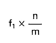
- the invention provides a method of processing the digital sound/data components of a time multiplexed television signal discrete lines of which sequentially contain a digital sound/data component at a first bit rate and a vision component and said digital sound/data components ar separated from said television signal and expanded to have a second bit rate, characterised in that each expanded digital sound/data component occupying the major part of a discrete period which period corresponds to the period of a line, said second bit rate being an integral sub-multiple of said first bit rate, the second bit rate being greater than where f, is the first bit rate, n is the number of bits in the compressed sound/data component in said television signal and m is the number of bits in a line period at said first bit rate.
- bit rate of the sound/data component By reducing the bit rate of the sound/data component from a first bit rate (which may be 20.25 M bits/s) to a much lower second bit rate simplifies the handling and circuitry requirements for or- ganising and demodulating the sound/data components.
- the invention additionally provides a television transmission system in which a first time multiplexed television signal having a given bandwidth is converted into a second television signal for transmission via a media with a bandwidth which is restricted with respect to that of the first television signal, in which discrete lines of said first television signal sequentially contain a digital sound/data component, a time compressed chrominance component and a time compressed luminance component, said digital sound/data component modulating a carrier at a first bit rate whilst said carrier is frequency modulated by said chrominance and luminance components, characterised in that said second television signal comprises a first carrier amplitude modulated by a video signal discrete lines of which sequentially contain the time compressed chrominance component and the time compressed luminance component at corresponding compression rates and located in corresponding positions as with said first television signal, said second television signal further comprising a second carrier located outside the modulated of said first carrier which second carrier is modulated by the digital sound/ data component at a second bit rate discrete periods of which, corresponding to the period of a line, contain the
- bit rate By expanding the sound/data component the bit rate is reduced which overcomes the problem of short delay reflections in co-axial cable systems and choosing this bit rate as an integral sub-multiple of the first bit rate makes in relatively simple to produce this second bit rate on conversion and to produce the first bit rate at the receiver. This first bit rate will be required at the receiver for synchronising purposes.
- the choice for the second bit rate means that additional bits should to be added to the expanded sound/data.
- the modulation of the first carrier by the video signal may be vestigial sideband amplitude modulation and the second carrier may be located on the vestigial side of the modulated first carrier.
- a pulse signal may be additionally present in each line of the vision signal of the second television signal, which pulse signal would be located within the position corresponding to that of the data/sound component in the first television signal.
- the integral sub-multiple for the second bit rate may be one fifth or less than one fifth and in aparticular embodiment is one sixth of the first bit rate.
- Additional digital components may be added to the expanded sound/data component during the minor part of each discrete period which additional digital components may convey additional sound/data information.
- the invention further provides apparatus for use with the above method comprising means for receiving a television signal discrete lines of which sequentially contain a digital sound/data component at a first bit rate and a vision component, and means for recovering the digital sound/ data component from said television signal, characterised in that said apparatus additionally comprises means for expanding the recovered sound/data component at a second bit rate such that the recovered component from each line of said first television signal occupies a major part of a discrete period which corresponds to the period of a television line, the second bit rate being an integral sub-multiple of the first bit rate which second bit rate is greater than where f, is the first bit rate, n is the number of bits in the sound/data component in said first television signal and m is the number of bits in a line period at the first bit rate.
- the invention also provides a conversion unit for use with the above television transmission system and which comprises means for receiving said first television signal discrete lines of which sequentially contain a digital sound/data component, a time compressed chrominance component and a time compressed luminance component with said digital sound/data component modulating a carrier at a first bit rate whilst the carrier is frequency modulated by said compressed chrominance and luminance components, means for frequency demodulating said modulated carrier to produce said compressed chrominance and luminance components and means for recovering the digital sound/data component from said modulated carrier, characterised in that said conversion unit additionally comprises means for amplitude modulating the demodulated compressed chrominance and luminance components onto a first carrier in such manner that the compression rates and positions of said components correspond to those in said first television signal, means for expanding the recovered sound/data component at a second bit rate such that the recovered component from each line of said first television signal occupies a major part of a discrete period which corresponds to the period of a television line, the second bit rate being an integral sub-multiple
- Such a unit may additionally comprise a vestigial sideband filter so that the first carrier is vestigial sideband amplitude modulated by said compressed chrominance and luminance components and means may also be provided for positioning the second carrier on the vestigial side of said first carrier.
- the conversion unit may further comprise means for generating a pulse signal at line rate, and means for adding this pulse signal to the vision signal of the second television signal in such manner that the pulse signal is located within the position corresponding to that of the sound/ data component in the first television signal.
- the above apparatus or conversion unit may additionally comprise means for adding digital components to the expanded digital sound/data component during the minor part of each discrete period and may also further comprise means for modulating the added digital components with sound/data information.
- the invention yet further provides a television receiver for use with the above television system which comprises selection means connected to a restricted bandwidth transmission media for selecting on from a number of transmision channels, a first signal processing arrangement connected to said selection means for processing the video signal conveyed by said first carrier, characterised in that said receiver additionally comprises a second processing arrangement for processing the sound/data information conveyed by said second carrier, said second processing arrangement for recovering a clocking signal corresponding to that of the first having means bit rate present in sound first television signal from the second bit rate present in said second television signal.
- a receiver means may be provided for producing timing signals for the processing of the chrominance and luminance components which timing signals are produced from information contained in the sound/data component, the pulse signal in the video signal then being recovered which is applied to the processing means to ensure a given time relationship between the pulse signal and the timing signals.
- This pulse signal may also be used to provide automatic gain control in the receiver.
- the receiver may also be a dual standard receiver to receive either the second television signal or a frequency multiplexed television signal. A number of processing stages in the receiver may then be common to both signals.
- the diagram of fig. 2 includes a conversion unit for use with the present invention for converting a received C-MAC DBS television signal into one suitable for applying a MAC television signal to a cable distribution system.
- This figure shows a dish aerial 1 of appropriate dimensions for receiving DBS television signals which are located in the 12 GHz broadcasting band. Attached to the aerial 1 is a down converter unit 2 in which the frequencies of the incoming signals are shifted such that they are positioned just above the UHF broadcasting bands and lie between 950 and 1750 MHz, so that they can be readily applied via a co-axial cable 3 to an input terminal 4 of the conversion unit.
- the signals at terminal 4 are applied to a tuner unit 5 where the required television signal is selected in the usual manner by mixing it with a tuned local oscillator signal to produce an intermediate frequency (i.f.) signal which in this case has a frequency of 134 MHz.
- the bandwidth of the tuner and the resulting i.f. signal is 27 MHz to match the bandwith of the DBS signal.
- Tuning in the tuner unit 5 is by means of a selection voltage applied over a connection 6 from a selector unit (not shown) applied by way of a first input of an adder circuit 7 whose output is connected to the appropriate input of the tuner unit 5.
- the adder circuit 7 has a second input to which an automatic frequency control (a.f.c.) voltage is applied over a connection 8, this a.f.c. voltage being added to the selection voltage to ensure correct tuning of the tuner unit 5.
- the i.f. signal from the tuner unit 5 is amplified in an amplifier stage 9 and applied to surface accoustic wave (S.A.W.) filter 10 having a pass band of 27 MHz centred on the i.f. of 134 MHz.
- S.A.W. surface accoustic wave
- the output of the SAW filter 10 is applied to a limiter and discriminator stage 11 in which the frequency modulated chrominance and luminance vision components of the i.f.
- the limiter and discriminator stage 11 also produces the a.f.c. voltage which is applied over connection 8 to adder circuit 7.
- the i.f. signal is also applied to a limiter and 2-4 PSK demodulator stage 13 in which the sound/ data component (194 bits at 20.25 Mbit/s) is recovered.
- This sound/data component in the form of bursts at 20.25 Mbit/s is applied to a sound/data processor 14 which has a number of functions one of which is to expand the sound/data component such that it has a much lower bit rate. Certain features of the processor 14 are shown in greater detail in fig. 3. In fig.
- the bursts of the 20.25 Mbit/s sound/data component are applied to the input A of the processor 14 from where they are applied as a first input to a phase comparator 15 a second input of which receives oscillations at the clocking frequency of 20.25 MHz from voltage controlled crystal oscillator 16.
- the comparator 15 produces a voltage at its output depending on the phase relationship between its two inputs which voltage is applied through a low pass filter 17 as the control input of the oscillator thus providing the voltage control for this oscillator.
- the output of the oscillator 16 is applied to a frequency divider 18 which divides the output of the oscillator by six to produce a second clocking frequency of 3.375 MHz.
- the burst at input 15 is also applied to a digital store 19 which may be in the form of a shift register, the burst of the sound/data component appearing during each line of the C-MAC signal being written in the store 19 at the clocking frequency of 20.25 MHz under the control of the oscillator 16.
- this component has to be expanded such that its bit rate is much lower than that present in the C-MAC signal.
- this component could be expanded to occupy a period of 64 ⁇ s which corresponds to the line period in a 625 line per frame, 25 frames per second television system and this would mean that the bit rate for the 194 bits of the sound/data component would need to be 3.0625 Mbit/s.
- Such a bit rate would be difficult to realise from the incoming bit rate and in addition it would be difficult to regenerate this original clocking frequency of 20.25 MHz from data at 3.0625 Mbit/s.
- the sound/data component is read out during a period which is less than 64 " at a bit rate which is higher than 3.0625 Mbit/s and which at the same time is an integral sub-multiple of the original bit rate of 20.25 Mbit/s (in this case one-sixth of the original bit rate).
- the sound/data component is therefore read out under the control of the second clocking frequency of 3.375 MHz during each 64 I ls period to occupy 194 bits of the 216 bits at that rate during such a period and is applied to a gated bit insertion stage 20.
- a second input of stage 20 is connected to the output of a bit generator 21 whose input receives the second clocking frequency of 3.375 MHz, which generator produces bits in a predetermined pattern (and could be used to carry additional information) which are added during the remaining 22 bits of each 64 I ls period in the gated bit insertion stage 20 to produce an extended sound/data component during each 64 l is (line) period which is present at output B of processor 14 whilst an output C carries the second clocking frequency of 3.375 MHz.
- the burst at input 15 is also applied to a sync. separator circuit 22 which recognises the synchronising information contained in the sound/data component and produces an output in response to this information which is applied to a sync. pulse generator 23 to produce a pseudo sync. pulse which is present at an output D of the converter unit 14, the purpose of which will be described later.
- the vision signal from the de-emphasis stage 12 is applied to a first input of a gated sync, insertion stage 26 whose second input receives the pseudo sync. pulse from the output D of the processor 14, this sync. pulse being gated into the vision signal during the period previously occupied by the 194 sound/data bits (approx. 9.58 ⁇ s).
- the combined sync. and vision signal from the gated sync. insertion stage 26 is applied to the modulation input of a modulator 27 in which this signal is amplitude modulated onto a vision carrier received at a second input from a first carrier oscillator 28, the frequency of the carrier being in the frequency bands used for cable distribution systems.
- the pulse is represented by 100% modulation of the carrier whilst the front and back porches are represented by 70% of carrier modulation.
- the zero-level of chrominance is represented by 50% of carrier modulations whilst the extremes of the chrominance component are represented by 89% and 11 % of carrier modulation.
- the black and white levels are respectively represented by 80% and 20% of carrier modulation.
- the ranges of the modulation for the chrominance and luminance components retains the 1.3 to 1 relationship between the maximum peak-to-peak amplitudes for these two components.
- the output from the modulator 27 is applied to a vestigial side band filter 29 to remove substantially all of the lower sideband of the amplitude modulated carrier from the modulator 27.
- the output from the filter 29 is applied to the first input of an adder circuit 30 whose output is connected to the output 31 of the conversion unit for application to a cable distribution system.
- the outputs B and C respectively conveying the extended sound/data component and the second clocking frequency (3.375 MHz) are applied to a digital modulator 32 which at a further input receives the sound carrier from a second carrier oscillator 33, whose frequency is above that of the first carrier oscillator 28, in which the sound carrier is digitally modulated by the extended sound/ data component for example using quadrature phase shift keying.
- the modulated sound carrier output is applied through a bandpass filter 34 to a second input of the adding circuit 30 for application to the output terminal 31.
- the frequency spectrum for the signal appearing at terminal 31 is shown in fig. 5A where the vision carrier is indicated at VC and the spectrum, of the vestigial sideband vision signal extends from approximately 1.25 MHz below the vision carrier to approximately 8.5 MHz above the vision carrier.
- the sound carrier indicated by SC is located 11 MHz above the vision carrier VC and the extended sound/data component modulation extends approximately 3 MHz about the sound carrier. It will be seen from fig. 5 that the modulated sound bandwidth lies outside the modulated vision bandwidth whilst the bandwidth occupied by the modulated vision and sound components together is approximately 14 MHz which is substantially half the 27 MHz bandwidth of the DBS C-MAC signal.
- the frequency of the second carrier oscillator 33 may lie below that of the first carrier oscillator, i.e. on the vestigial sideband side of the modulated first carrier.
- the frequency spectrum for the signal appearing at terminal 31 suitable for use with two adjacent cable television channels for the U.K. (8 MHz per channel) in such a case is shown in fig. 5B where the vision carrier is indicated at VC and the spectrum of the vestigial sideband vision signal extends from approximately 1.25 MHz below the vision carrier to approximately 8.5 MHz above the vision carrier.
- the sound carrier indicated by SC is located 3.5 MHz below the vision carrier VC and the extended sound/data component modulation extends approximately 3 MHz about the sound carrier.
- Fig. 5C shows the corresponding frequency spectrum suitable for use with two adjacent cable television channels for Europe (7 MHz per channel) and is similar to fig. 5B except that the vestigial sideband vision signal extends from approximately 1 MHz below the vision carrier whilst the sound carrier SC is located 2.85 MHz below the vision carrier VC. In both the U.K. and European cases the maximum amplitude of the sound/data signal may be of the order of-20 dB relative to the vision carrier. It will be seen from fig. 5B and 5C that the modulated sound bandwidth also lies outside the modulated vision bandwidth whilst the bandwidth occupied by the modulated vision and sound components together is approximately 14 MHz which is substantially half the 27 MHz bandwidth of the DBS C-MAC signal.
- the processor 14 described with reference to fig. 3 may also be used, with some modification, in a television receiver intended to receive the C-MAC DBS television signal directly from a satellite.
- the sync. pulse generator 23 would not be required and the sync. separator circuit 22 would supply the sync. information for the receiver.
- the receiver itself would be similar to the conversion unit of fig. 2 up to the de-emphasis stage 12 and the processor 14.
- the output of the de-emphasis stage 12 would then be connected to the necessary circuitry for demodulating the vision components whilst the outputs B and C of processor 14 would be connected to the necessary circuitry for demodulating the sound/data components.
- vision and sound/data circuitry is included in fig. 6.
- the reduction of the bit rate for the sound/data components in such a receiver would simplify the operation of the associated demodulation circuitry.
- Fig. 6 is a block diagram of a television receiver capable of receiving television signals from a cable distribution system whether the signals be in one of the forms described above or according to the U.K. or European PAL-I standards i.e. PAL-I or PAL-B/G.
- the receiver comprises an input terminal 35 for connection to the cable system which is connected to a tuner unit 36 capable of covering the VHF and UHF frequency bands (40 to 860 MHz), the tuner unit having a received signal bandwidth of approximately 15 MHz.
- the tuner unit 36 has a local oscillator tuned by means of a control voltage applied over a connection 37 and an adder circuit 38 in a similar manner to the tuner unit 5 in fig. 2, an a.f.c.
- the i.f. signal from the tuner unit 36 will depend upon the signal being processed though for either type of signal the vision carrier i.f. will be located at the same frequency e.g. 39.5 MHz where the receiver also receives PAL-I or 38.9 MHz where it also receives PAL-B/G.
- the i.f. of the sound carrier will then be located at 33.5 MHz whilst that for the MAC signal will be located at 28.5 MHz if the sound carrier SC is located above the vision carrier VC (fig. 5A) and 43 MHz if the sound carrier SC is located below the vision carrier VC (fig. 5B).
- the i.f. of the sound carrier will be located at 33.4 MHz whilst that for the MAC signal will be located at 37.9 MHz if the sound carrier SC is located above the vision carrier VC (fig. 5A) and 41.75 MHz if the sound carrier SC is located below the vision carrier VC (fig. 5C).
- This output of the tuner unit 36 is amplified by an amplifier stage 40 whose amplified output is applied to a first systems switch 41 in which the incoming signal may be applied either to an upper (PAL) output or a lower (MAC) output.
- the PAL output is connected to a first (PAL) bandpass filter 42 having a bandpass characteristic of the form substantially as shown in fig.
- the MAC output of switch 41 is connected to a second (MAC vision) bandpass filter 43 and to a third (MAC sound/data) bandpass filter 44.
- the bandpass characteristic of filter 43 for receivers which also receive the PAL-I signal is shown in fig. 7Ab or 7Bb whilst that for receivers which also receive the PAL-BIG signal is shown in fig. 7Cb.
- the bandpass characteristic of filter 44 for receivers which also receive the PAL-I signal is shown in fig. 7Ac for the case where the sound carrier SC is located above the vision carrier VC (fig. 5A) and in fig.
- the bandpass characteristic for filter 44 will be as shown in fig. 7Cc.
- the bandpass filters 42, 43 and 44 may conveniently be surface accoustic wave filters.
- the outputs of the first and second filters 42 and 43 are connected to the input of i.f. amplifier and detector stage 45 which may conveniently incorporate the Philips integrated circuit TDA 3540 or TDA 3541 (the type chosen being dependent on the tuner circuit 36) and for which Development Sample Data has been issued. Besides the amplifying and detection functions of this integrated circuit it also produces the a.f.c.
- connection 39 an automatic gain control (a.g.c.) voltage for the tuner unit 36 which it applied thereto over a connection 46, the production of this a.g.c. voltage being one reason why the pseudo sync. pulse is introduced into the vision signal (MAC) at the gated sync. insertion stage 26 of the conversion unit of fig. 2 (the PAL-I signal already contains a corresponding sync. signal).
- a.g.c. automatic gain control
- the detected output from the stage 45 is applied to a second systems switch 47 being similar to and operated simultaneously with switch 41.
- the upper (PAL) output of switch 47 is applied to a PAL signal decoder circuit generally depicted by the block 48 where the luminance and chrominance subcarrier components are used (when set for PAL operation) to produce the luminance Y' and the red (R-Y') and blue (B-Y') colour difference signals. It is considered that the construction and operation of a PAL signal decoder is so well known as to not warrant a detailed description of it construction and operation.
- the PAL output of the switch 47 is also connected to a further bandpass filter 49 having a passband at 6 MHz (PAL-I) or 5.5 MHz (PAL-B/G) to select the intercarrier frequency modulated sound signal when a PAL signal is present, this signal being further processed and demodulated in an intercarrier sound stage 50 to produce the demodulated sound signal at its output for application to a loudspeaker (not shown).
- a sync. separator stage 51 is also connected to the PAL output of switch 47 which in the presence of a PAL signal produces line f H ' and field f v ' sync. pulses from this signal.
- the output of the third bandpass filter 44 is connected to stages 52 which with a MAC signal present recovers from the sound carrier i.f. the second clock frequency of 3.375 MHz at an output 53 and the continuous sound/data bit stream at 3.375 Mbit/s at an output 54. These outputs are applied to respective inputs E and F of a unit 55 which produces clocking signals, sync. signals and control signals for the further processing of the MAC signal.
- the unit 55 is shown in greater detail in fig. 8 where it will be seen that the 3.375 MHz clocking frequency input E is connected to a first input a phase comparator 56 a second input of which receives a signal at this clocking frequency of 3.375 MHz from a divider circuit 57 which divides a signal applied thereto by 2.
- the output of the comparator 56 is a voltage dependent on the phase relationship between its two inputs, this voltage being applied through a low pass filter 58 to the control input of a voltage controlled crystal oscillator 59 of frequency 20.25 MHz.
- the output of oscillator 59 is successively connected through a 3 divider stage 60 which divides by - and a further 2 divider stage 61 which divides by 2 to the input of divider stage 57.
- the divider stages 60, 61 and 57 respectively produces outputs at 13.5 MHz, 6.75 MHz and 3.375 MHz which together with the output of oscillator 59 are applied to a control stage 62 to which the input at terminal F is also applied.
- a further input of the control stage 62 also receives the pseudo sync.
- This pseudo sync. pulse present in the MAC vision signal is separated from the signal present at the MAC output of switch 47 by a pseudo sync. detector 63 whose output is connected to the input G (fig. 6).
- the control stage 62 produces timing signals necessary for the processing of the MAC vision signal and which appear at outputs H and I of unit 55 for application to multi-lead connections 64 and 64' and include the appropriate clocking frequencies. Outputs of the control stage 62 are also applied to a sync. generator 65 which from these inputs produce line (f H ) and field (f v ) sync. signals which are applied to output terminals J and K of the unit 55.
- the MAC output of the switch 47 is connected to an analogue-to-digital converter 66 which also receives control and 20.25 MHz clock signals from unit 55 over the connection 64.
- the time sequential vision signal is converted to digital form in the converter 66 the parallel bits of which are conveyed over multi-lead connection 6 to a MAC vision processor 68 where the chrominance and luminance components are separately stored and expanded in known manner under the control of the control signals and clock signals present in connection 64'.
- the processor 68 has three outputs which are connected as shown to respective digital-to-analogue converters 69, 70 and 71 and low pass filters 72, 73 and 74 to produce respective luminance (Y) and red (R-Y) and blue (B-Y) colour difference signals.
- the Y, R-Y and B-Y signals from a processed MAC signal and the Y', (R-Y') and (B-Y') signals from a processed PAL signal are applied to respective inputs of a further multi-pole systems switch 75 to which the sync. signals f H , f v and F H ', F v ' are also applied, the switch 75 being operated simultaneously with switches 40 and 47. Switch 75 applies the appropriate signals, depending on the type of signal received, to a display unit 76 where these signals are further processed in known manner to produce a television display.
- the clocking frequency 53 and sound/data 54 outputs of stage 52 are also applied to a sound/ data decoder 77 which separates and de-multiplexes the sound and data signals.
- the decoder 65 is not shown in greater detail as its construction depends on the composition of the sound/data component.
- the sound signals from the decoder will be applied to the loudspeaker through a further systems switch (also not shown) which operates simultaneously with switches 41, 47 and 75.
- the dual standard receiver utilises a number of common stages no matter which of the signals is being received. Whilst reference has been made to one of the signals being of the PAL standard it could be any form of frequency multiplexed colour television signal.
Landscapes
- Engineering & Computer Science (AREA)
- Multimedia (AREA)
- Signal Processing (AREA)
- Power Engineering (AREA)
- Television Systems (AREA)
- Color Television Systems (AREA)
- Two-Way Televisions, Distribution Of Moving Picture Or The Like (AREA)
Claims (22)


Applications Claiming Priority (4)
| Application Number | Priority Date | Filing Date | Title |
|---|---|---|---|
| GB08306921A GB2137843A (en) | 1983-03-14 | 1983-03-14 | Television Transmission Systems |
| GB8306921 | 1983-03-14 | ||
| GB838314434A GB8314434D0 (en) | 1983-05-25 | 1983-05-25 | Television transmission system |
| GB8314434 | 1983-05-25 |
Publications (2)
| Publication Number | Publication Date |
|---|---|
| EP0121967A1 EP0121967A1 (fr) | 1984-10-17 |
| EP0121967B1 true EP0121967B1 (fr) | 1986-10-29 |
Family
ID=26285503
Family Applications (1)
| Application Number | Title | Priority Date | Filing Date |
|---|---|---|---|
| EP84200336A Expired EP0121967B1 (fr) | 1983-03-14 | 1984-03-09 | Transmissions de télévision |
Country Status (6)
| Country | Link |
|---|---|
| US (1) | US4665427A (fr) |
| EP (1) | EP0121967B1 (fr) |
| AU (1) | AU568262B2 (fr) |
| DE (1) | DE3461136D1 (fr) |
| ES (2) | ES530511A0 (fr) |
| FI (1) | FI74178C (fr) |
Families Citing this family (20)
| Publication number | Priority date | Publication date | Assignee | Title |
|---|---|---|---|---|
| GB8414665D0 (en) * | 1984-06-08 | 1984-07-11 | Philips Electronic Associated | Television transmission system |
| GB2172478A (en) * | 1985-03-12 | 1986-09-17 | Philips Electronic Associated | Handing data in television signals |
| FR2609228B1 (fr) * | 1986-12-24 | 1989-12-01 | France Etat | Procede de diffusion numerique dans des canaux de television |
| US5053859A (en) * | 1987-09-02 | 1991-10-01 | Scientific-Atlanta, Inc. | High definition B-MAC television signal transmission system |
| US4965661A (en) * | 1988-08-04 | 1990-10-23 | Scientific-Atlanta, Inc. | Method and apparatus for increasing the definiton of an NTSC video signal using an augmentation channel |
| DE3731166A1 (de) * | 1987-09-17 | 1989-03-30 | Thomson Brandt Gmbh | Videorecorder mit verbesserter farbaufzeichnung |
| FR2630281B1 (fr) * | 1988-04-19 | 1990-08-17 | France Etat | Procede de diffusion de programmes de television derive du type mac/paquets, et installation de mise en oeuvre du procede |
| US5101272A (en) * | 1988-05-25 | 1992-03-31 | Picker International, Inc. | Dual bandwidth/gain video preamplifier |
| FR2632149B1 (fr) * | 1988-05-26 | 1990-09-21 | Matra Communication | Procede de diffusion de programmes de television du type mac/paquet et recepteur pour un tel programme |
| EP0352963A3 (fr) * | 1988-07-28 | 1990-12-12 | British Broadcasting Corporation | Méthode et appareil de réception de signaux de télévision à haute définition |
| US4984067A (en) * | 1988-08-31 | 1991-01-08 | North American Philips Corporation | HDNTSC signal transmission and reception with time and frequency multiplexing |
| US4989091A (en) * | 1988-11-16 | 1991-01-29 | Scientific-Atlanta, Inc. | Scan converter for a high definition television system |
| JP2781906B2 (ja) * | 1991-03-29 | 1998-07-30 | パイオニア株式会社 | ケーブルネットにおけるcatvセンター装置及び番組供給方法 |
| US5138659A (en) * | 1991-05-02 | 1992-08-11 | General Instrument Corporation | Conversion of television signal formats with retention of common control data stream |
| FR2686473B1 (fr) * | 1992-01-16 | 1994-04-15 | Matra Communication | Codeur multicomposantes x-paquets et decodeur correspondant. |
| US5588022A (en) * | 1994-03-07 | 1996-12-24 | Xetron Corp. | Method and apparatus for AM compatible digital broadcasting |
| US6545728B1 (en) * | 1994-05-04 | 2003-04-08 | Samsung Electronics Co., Ltd. | Digital television receivers that digitize final I-F signals resulting from triple-conversion |
| US5870439A (en) * | 1997-06-18 | 1999-02-09 | Lsi Logic Corporation | Satellite receiver tuner chip having reduced digital noise interference |
| US6169584B1 (en) * | 1997-12-05 | 2001-01-02 | Motorola, Inc. | Automatic modulation control of sync suppressed television signals |
| US6778108B2 (en) * | 2002-07-09 | 2004-08-17 | Ipmobilenet, Inc. | Method and apparatus for compression of binary data |
Family Cites Families (11)
| Publication number | Priority date | Publication date | Assignee | Title |
|---|---|---|---|---|
| NL7017427A (fr) * | 1970-11-28 | 1972-05-30 | Philips Nv | |
| US3789137A (en) * | 1972-04-07 | 1974-01-29 | Westinghouse Electric Corp | Time compression of audio signals |
| DE2629706C3 (de) * | 1976-07-02 | 1986-07-10 | Robert Bosch Gmbh, 7000 Stuttgart | Verfahren zur Übertragung und/oder Aufzeichnung von Farbfernsehsignalen |
| US4281348A (en) * | 1979-08-02 | 1981-07-28 | Matsushita Electric Industrial Co., Ltd. | Television signal receiving apparatus |
| US4335393A (en) * | 1980-04-15 | 1982-06-15 | Harris Video Systems, Inc. | Method and system using sequentially encoded color and luminance processing of video type signals to improve picture quality |
| FR2513465A1 (fr) * | 1981-09-21 | 1983-03-25 | Eeco Inc | Procede et appareil pour reproduire plusieurs types d'informations de television |
| US4476484A (en) * | 1982-06-24 | 1984-10-09 | At&T Bell Laboratories | Technique for providing compatibility between high-definition and conventional color television |
| ATE22767T1 (de) * | 1982-07-23 | 1986-10-15 | British Telecomm | Uebertragung von daten. |
| ATE34265T1 (de) * | 1982-11-30 | 1988-05-15 | British Telecomm | Uebertragung eines fernsehsignals. |
| NL8304007A (nl) * | 1983-11-22 | 1985-06-17 | Philips Nv | Kleurentelevisie-transmissie- respektievelijk informatie-opslagsysteem met tijdmultiplexkodering en daartoe geschikte informatiegever en -ontvanger. |
| US4544950A (en) * | 1984-01-03 | 1985-10-01 | At&T Bell Laboratories | Technique for the transmission of video and audio signals over a digital transmission system |
-
1984
- 1984-03-02 US US06/585,705 patent/US4665427A/en not_active Expired - Fee Related
- 1984-03-09 EP EP84200336A patent/EP0121967B1/fr not_active Expired
- 1984-03-09 FI FI840969A patent/FI74178C/fi not_active IP Right Cessation
- 1984-03-09 DE DE8484200336T patent/DE3461136D1/de not_active Expired
- 1984-03-12 ES ES530511A patent/ES530511A0/es active Granted
- 1984-03-14 AU AU25608/84A patent/AU568262B2/en not_active Ceased
- 1984-11-30 ES ES538130A patent/ES8606771A1/es not_active Expired
Also Published As
| Publication number | Publication date |
|---|---|
| ES8606771A1 (es) | 1986-04-01 |
| FI74178B (fi) | 1987-08-31 |
| DE3461136D1 (en) | 1986-12-04 |
| AU568262B2 (en) | 1987-12-17 |
| FI840969A7 (fi) | 1984-09-15 |
| AU2560884A (en) | 1984-09-20 |
| ES538130A0 (es) | 1986-04-01 |
| EP0121967A1 (fr) | 1984-10-17 |
| US4665427A (en) | 1987-05-12 |
| FI840969A0 (fi) | 1984-03-09 |
| FI74178C (fi) | 1987-12-10 |
| ES8506960A1 (es) | 1985-08-01 |
| ES530511A0 (es) | 1985-08-01 |
Similar Documents
| Publication | Publication Date | Title |
|---|---|---|
| US4665427A (en) | Method and apparatus for converting C-MAC television signals for transmission over a limited bandwidth medium | |
| US5946047A (en) | Network system for handling digital data over a TV channel | |
| US5946048A (en) | Network device for handling digital data over a TV channel | |
| US4944032A (en) | Multiplex signal processing apparatus | |
| Sabatier et al. | The D2-MAC Packet System for All Transmission Channels | |
| EP0485478B1 (fr) | Transmission d'informations auxiliaires dans un signal de television | |
| CA2209744C (fr) | Methode et dispositif de commutation des modes de fonctionnement d'un recepteur de tvhd | |
| US4502078A (en) | Digital television receivers | |
| US4706109A (en) | Television transmission system | |
| US4975775A (en) | Tuner for receiving television signal in frequency division multiplex system and television signal in time division multiplex system | |
| US3504115A (en) | Fm television signal transmission system | |
| WO1986003919A1 (fr) | Amelioration du rapport signal/bruit en utilisant des signaux de bande des plus basses frequences dans un systeme de television fm | |
| GB2145610A (en) | Television transmission systems | |
| GB2137843A (en) | Television Transmission Systems | |
| CA1326287C (fr) | Generateur de frequence pour le codage et le decodage de signaux de television en couleurs mac a largeur de bande etendue | |
| US4943847A (en) | Extended definition television | |
| EP0319109A1 (fr) | Système de télédiffusion pour la transmission d'un signal de télévision à multiplexage temporel | |
| EP0276214B1 (fr) | Procede et appareil de transmission de signaux de television | |
| Phillips et al. | Satellite broadcasting: System concepts and the television transmission standards for europe | |
| EP0099341A2 (fr) | Procédé d'émission et de réception de signaux de télevision compatibles en couleur sur deux canaux pour la transmission par satellite et dispositif pour la mise en oeuvre de ce procédé | |
| KR0140600B1 (ko) | 텔레비젼의사운드모드판별방법및장치 | |
| JP2832961B2 (ja) | Catv伝送方式 | |
| EP0374128A2 (fr) | Méthode d'èmission et de reception de signaux de télévsion couleur sur deux canaux pour la transmission par satellite et dispositif associé | |
| Lothian et al. | Transmission using MAC signal formats | |
| Mothersole | Developments in broadcasting technology and their effect on TV receiver design |
Legal Events
| Date | Code | Title | Description |
|---|---|---|---|
| PUAI | Public reference made under article 153(3) epc to a published international application that has entered the european phase |
Free format text: ORIGINAL CODE: 0009012 |
|
| AK | Designated contracting states |
Designated state(s): DE FR GB IT NL SE |
|
| 17P | Request for examination filed |
Effective date: 19841224 |
|
| GRAA | (expected) grant |
Free format text: ORIGINAL CODE: 0009210 |
|
| AK | Designated contracting states |
Kind code of ref document: B1 Designated state(s): DE FR GB IT NL SE |
|
| REF | Corresponds to: |
Ref document number: 3461136 Country of ref document: DE Date of ref document: 19861204 |
|
| ITF | It: translation for a ep patent filed | ||
| ET | Fr: translation filed | ||
| PLBE | No opposition filed within time limit |
Free format text: ORIGINAL CODE: 0009261 |
|
| STAA | Information on the status of an ep patent application or granted ep patent |
Free format text: STATUS: NO OPPOSITION FILED WITHIN TIME LIMIT |
|
| 26N | No opposition filed | ||
| ITTA | It: last paid annual fee | ||
| EAL | Se: european patent in force in sweden |
Ref document number: 84200336.0 |
|
| ITPR | It: changes in ownership of a european patent |
Owner name: CAMBIO RAGIONE SOCIALE;PHILIPS ELECTRONICS N.V. |
|
| PGFP | Annual fee paid to national office [announced via postgrant information from national office to epo] |
Ref country code: DE Payment date: 19950529 Year of fee payment: 12 |
|
| REG | Reference to a national code |
Ref country code: FR Ref legal event code: CD |
|
| NLT1 | Nl: modifications of names registered in virtue of documents presented to the patent office pursuant to art. 16 a, paragraph 1 |
Owner name: PHILIPS ELECTRONICS N.V. |
|
| PGFP | Annual fee paid to national office [announced via postgrant information from national office to epo] |
Ref country code: GB Payment date: 19960229 Year of fee payment: 13 |
|
| PGFP | Annual fee paid to national office [announced via postgrant information from national office to epo] |
Ref country code: SE Payment date: 19960326 Year of fee payment: 13 |
|
| PGFP | Annual fee paid to national office [announced via postgrant information from national office to epo] |
Ref country code: FR Payment date: 19960327 Year of fee payment: 13 |
|
| PGFP | Annual fee paid to national office [announced via postgrant information from national office to epo] |
Ref country code: NL Payment date: 19960328 Year of fee payment: 13 |
|
| PG25 | Lapsed in a contracting state [announced via postgrant information from national office to epo] |
Ref country code: DE Effective date: 19961203 |
|
| PG25 | Lapsed in a contracting state [announced via postgrant information from national office to epo] |
Ref country code: GB Effective date: 19970309 |
|
| PG25 | Lapsed in a contracting state [announced via postgrant information from national office to epo] |
Ref country code: SE Effective date: 19970310 |
|
| PG25 | Lapsed in a contracting state [announced via postgrant information from national office to epo] |
Ref country code: NL Effective date: 19971001 |
|
| GBPC | Gb: european patent ceased through non-payment of renewal fee |
Effective date: 19970309 |
|
| PG25 | Lapsed in a contracting state [announced via postgrant information from national office to epo] |
Ref country code: FR Free format text: LAPSE BECAUSE OF NON-PAYMENT OF DUE FEES Effective date: 19971128 |
|
| NLV4 | Nl: lapsed or anulled due to non-payment of the annual fee |
Effective date: 19971001 |
|
| EUG | Se: european patent has lapsed |
Ref document number: 84200336.0 |
|
| REG | Reference to a national code |
Ref country code: FR Ref legal event code: ST |