EP0122029A2 - Sandgiessen und Regenerieren von Giessereisand - Google Patents
Sandgiessen und Regenerieren von Giessereisand Download PDFInfo
- Publication number
- EP0122029A2 EP0122029A2 EP84301529A EP84301529A EP0122029A2 EP 0122029 A2 EP0122029 A2 EP 0122029A2 EP 84301529 A EP84301529 A EP 84301529A EP 84301529 A EP84301529 A EP 84301529A EP 0122029 A2 EP0122029 A2 EP 0122029A2
- Authority
- EP
- European Patent Office
- Prior art keywords
- sand
- fluid bed
- temperature range
- casting
- treatment temperature
- Prior art date
- Legal status (The legal status is an assumption and is not a legal conclusion. Google has not performed a legal analysis and makes no representation as to the accuracy of the status listed.)
- Granted
Links
Images


Classifications
-
- B—PERFORMING OPERATIONS; TRANSPORTING
- B22—CASTING; POWDER METALLURGY
- B22C—FOUNDRY MOULDING
- B22C5/00—Machines or devices specially designed for dressing or handling the mould material so far as specially adapted for that purpose
- B22C5/08—Machines or devices specially designed for dressing or handling the mould material so far as specially adapted for that purpose by sprinkling, cooling, or drying
Definitions
- This invention relates generally to casting metal using shape-defining parts such as moulds and/or cores made of organically bonded foundry sand and more particularly relates to a method of reclaiming the organically bonded foundry sand after it has been used for casting.
- organically bonded foundry sand has been reclaimed by burning off the organic binder components using a fuel fired (gas or oil) heated system operating in the temperature range 800°C to 1000°C and in which the used sand is agitated during burning off of the organic binder components, for example in a rotary kiln.
- a fuel fired (gas or oil) heated system operating in the temperature range 800°C to 1000°C and in which the used sand is agitated during burning off of the organic binder components, for example in a rotary kiln.
- the present invention provides a method of reclaiming used foundry sand containing an organic binder comprising the steps of separating said sand from a casting, supplying said sand to a fluid bed, fluidising said sand in said fluid bed with combustion supporting gas introduced into said sand at a plurality of locations so that the sand remains in said fluid bed in a fluidised state at an elevated treatment temperature range to reclaim said sand and removing reclaimed sand from said fluid bed.
- said sand is supplied to said fluid bed without fluidising said sand prior to entry into said fluid bed.
- said sand is not heated in the presence of combustion supporting gas prior to supplying said sand to said treatment station, and in particular said sand is not heated whilst being fluidised by combustion supporting gas. This is to avoid evolution of fumes prior to heating of the sand at the treatment station since the sand is brought to the treatment temperature range relatively quickly, e.g. in the order of ten secs. If the used sand is brought relatively slowly to the treatment temperature range in the presence of fluidising gas, then excessive fumes will be evolved.
- Said s ⁇ nd may be supplied into said fluid bed in said treatment temperature range by virtue of being heated in a metal casting process in which said sand has been previously used, the metal casting temperature and the metal-to-sand ratio being such that the sand is heated so as to be in the treatment temperature range.
- the sand may be initially at or substantially at ambient temperature and said sand may be supplied into said fluid bed at or substantially at ambient temperature and heat is applied to said sand in said fluid bed to bring said sand to said treatment temperature range.
- said sand may be supplied into said fluid bed at a temperature between ambient temperature or substantially ambient temperature and said treatment temperature range by virtue of being heated in a metal casting process in which said sand has been previously used and further heat is applied to said sand in said fluid bed to bring said sand to said treatment temperature range.
- said sand may be introduced into a first fluid bed section wherein said sand is fluidised by said combustion supporting gas and heat is applied to said sand to heat said sand to said treatment temperature range and wherein said sand is partially reclaimed and the partially reclaimed sand passes into a further fluid bed section wherein said sand is fluidised by said combustion supporting gas at a temperature in said treatment temperature range to continue reclamation of the sand.
- the sand may remain in the further fluid bed section without the application of heat or with the application of heat but a lesser amount of heat than is applied in the first fluid bed section.
- Said fluid bed or fluid bed section may be heated by means which avoid combustion of fuel within said sand so that said combustion supporting gas is available for combustion of the binder.
- Said sand may be heated by a plurality of heating elements immersed in the sand, the heating elements may be electrical heating elements immersed in the sand, or a combustion chamber and/or smoke tubes of a furnace in which fuel is burned.
- the sand After treatment of the sand in the first fluid bed section or the first and second fluid bed sections where two fluid bed sections are provided, the sand may be passed to a cooling fluid bed section wherein said sand is fluidised and cooled to a desired temperature;
- said sand After separating said sand from said casting, said sand may be reduced to grain size or substantially to grain size.
- Said sand may be selected from the group consisting of silica, zircon, olivine or chromite sand.
- the binder may be selected from the group consisting of a chemically hardened resin binder or a thermo-setting resin or a "hot box” resin and may be selected from the group consisting of phenolic, furane, isocyanate or acrylic resin binder.
- the treatment temperature may lie in the range 250°C to 600°C, and preferably lies in the range 300°C to below 400°C and more preferably lies in the range 400°C to 500°C, and still more preferably lies in the range 450°C to 500°C.
- a method of making a metal casting comprising the steps of making a mould using reclaimed used foundry sand and an organic binder, hardening the mould, casting molten metal into the mould to make a casting, separating said sand from the casting, reclaiming said sand by a method according to the first aspect of the invention and then using the thus reclaimed sand in a repetition of the method.
- the metal may be a non-ferrous metal selected from the group consisting of aluminium, magnesium, copper and alloys based on said metals and said reclaimed sand of which the mould is made may be predominently reclaimed used zircon sand.
- the mould may comprise in addition to a. catalyst or hardening agent for the resin binder;
- Said sand of which the mould is made may comprise wholly or substantially wholly zircon sand.
- the metal may be melted in a melting vessel, transferred from the melting vessel to a casting vessel and transferred upwardly from the casting vessel into the mould.
- the metal may be transferred from the melting vessel into the casting vessel by flow of metal under gravity and the level of the top surface of the metal as the metal leaves the melting vessel may be above the top surface of the metal in the casting vessel by not more than a maximum distance above which excessive turbulence occurs; this maximum distance may lie within the range 50mm to 200mm.
- zircon sand as a foundry moulding material is welt known in the production of iron and steel castings.
- Zircon sand is used mainly because of its high refractoriness, i.e. it does not fracture nor melt under conditions of thermal shock when casting ferrous materials.
- Usually such moulds are produced by the Croning (Shell) process, which uses phenolic based thermo- setting resins. Although the process has a reasonable reputation for the accuracy of the resulting castings, the accuracy is necessarily limited by the use of hot metal patterns, which are subject to thermal distortion and the distortion of the thin shell moulds.
- the expensive zircon sand is re-claimed by a number of existing thermal reclamation systems, most of which heat the sand to a temperature in the range 800°C to 1,000 C to burn off the remaining resin prior to re-coating with fresh resin.
- the high cost of such reclamation is usually recoverable in the relatively high price of such ferrous shell-moulded castings.
- zircon sand and its reclamation in accordance with the present invention provides a metal casting process having a number of extremely important and unexpected benefits as follows
- the accuracy of cored holes and wall thicknesses defined by cores are improved by a factor of up to twenty times. External features of castings are typically five times more accurate than their silica sand cast counterparts. This improvement in accuracy follows from the low expansion combined with the high thermal capacity of zircon sand compared to silica. It enables the accuracy to exceed the accuracy of all other casting methods known to date including investment and pressure die casting. The high thermal capacity increases freezing rate and also improves mechanical properties.
- the levels of addition of the resin binder are significantly lower than those used for the Croning Shell Process. Because the patterns are used at or near to room temperature, they retain their accuracy and so produce accurate moulds and cores. Also, the moulds can be made of any convenient thickness as a thick shell, or in the form of block moulds, or can be made in steel boxes or frames. In this way, also, accuracy can be conserved (compared and contrasted with a thin Croning Shell mould which is easily distorted).
- an apparatus for reclaiming used foundry sand containing an organic binder comprising means for separating a mass of said sand from a casting, sand supply means to supply the separated sand to a fluidised bed, fluidising means to introduce combustion supporting gas into said sand at a plurality of locations in said fluid bed to fluidise the bed, means to maintain said sand in said fluid bed in an elevated treatment temperature range to reclaim said sand and means for removing the reclaimed sand from the fluid bed.
- said sand supply means supplies said sand to said fluid bed without fluidising said sand prior to entry of said sand into said fluidised bed.
- Said sand supply means may supply said sand to said fluid bed without heating said sand.
- said sand supply means may restrict contact between the sand and combustion supporting gas prior to introduction of the sand into the fluid bed.
- Said fluid bed may have heating means to heat said sand to said treatment temperature range.
- Said fluid bed may comprise a first fluid bed section into which said sand supply means supplies said sand, in use, and having fluidising means to introduce combustion supporting gas into said sand at a plurality of locations to fluidise the bed and a heating means to heat the bed to said treatment temperature range to partially reclaim said sand and sand passage means to pass partially reclaimed heated sand from the first fluid bed section to a further fluid bed section having fluidising means to introduce combustion supporting gas into the sand in the further fluid bed section at a plurality of locations to fluidise the bed and means to maintain the bed in the further fluid bed section in said treatment temperature range whereby reclamation of the sand is continued.
- Means may be provided whereby said sand remains in said further fluid bed section in said treatment temperature range without application of heat so as to continue reclamation utilising heat in said sand from the first fluid bed section.
- said further fluid bed section may be provided with heating means whereby said sand is maintained in said further fluid bed section in said treatment temperature range so as to continue reclamation partly by utilising heat in said sand from said first fluid bed section and with application of a lesser amount of heat than is applied in said first fluid bed section.
- the heating means may comprise a plurality of heating elements immersible in the sand.
- the heating elements may comprise electrical heating elements which may be electrical conductors in direct contact with the sand and through which electrical heating current at low voltage is passed, in use.
- the heating elements may comprise a combustion chamber and/or smoke tubes of a furnace in which fuel is burned, in use.
- the fluidising means may comprise a plurality of discrete openings through which said combustion supporting gas is directed to the sand, said openings being provided with shield means to shield the openings from ingress of sand.
- Means may be provided to reduce the sand to grain size or substantially to grain size after separating said sand from said casting.
- a foundry plant suitable for casting aluminium, magnesium, copper and alloys based on said metals or the like comprises a moulding station 10 where moulds are made of organically bonded foundry sand, in the present example zircon sand, but which may be made of other sands such as silica sand, olivine sand, chromate sand or a mixture of such sands.
- the sand is bonded with an organic binder such as a chemically hardened resin, such as a gas hardened resin, for example furane resin with methyl ethyl ketone peroxide (MEKP) hardened with S0 2 or isocyanate resin, hardened with amine gas or acrylic resin with MEKP hardened with S0 21 or a liquid catalyst hardened resin, for example furane resin hardened with sulphonic acid, or a thermosetting resin for example a thermosetting phenolic resin or "hot box" resin, or with any binder which can be reclaimed by heating in the presence of a combustion supporting gas to produce gaseous products of combustion/oxidation.
- a chemically hardened resin such as a gas hardened resin, for example furane resin with methyl ethyl ketone peroxide (MEKP) hardened with S0 2 or isocyanate resin, hardened with amine gas or acrylic resin with MEKP hardened with S0 21 or a liquid catalyst hardened resin, for
- the mould may be made by ramming but, in the present example, are blown using an automatic mould blowing machine.
- the mould may be used in conventional mould boxes or a boxless process, as in the present example may be used.
- the mould comprises 98% zirconium silicate sand; 0.55% furane resin, by weight of sand; 0.20% methyl ethyl ketone peroxide, by weight of sand; 2% usual impurities such as oxides of transition elements and bound with furane resin.
- the resin was hardened using S02 gas amounting to about 0.25% SQ2 equivalent by weight of sand.
- the sand has an average grain size of 145mm.
- the mould may comprise 50% to 100% zircon sand, by total weight of sand; 0.4% to 1% resin binder, by total weight of sand; 0% to 50% sand or sands other than zircon sand, by total weight of sand.
- the sand comprises wholly or substantially wholly zircon sand.
- the zircon sand may have an average particle grain size lying in the range 50 to 500mm.
- a core or cores similarly made of organic resin bonded sand either the same sand and binder system as the remainder of the mould or otherwise, is positioned, as necessary, within the mould cavity at a mould assembly station I where the cope and drag halves of the mould are closed.
- moulds are transferred by a conveyor 12 to a casting station 13 where molten metal, in the present example magnesium alloy, is cast through ingates into the mould cavity and around the core or cores when present. Details of the melting of the metal and casting are described below with reference to Figure 2.
- molten metal in the present example magnesium alloy
- the filled mould is transferred by a conveyor 12 to a shakeout station 14 where the sand of the mould and core or cores, when present, is shaken out of the casting and the used sand is fed by a conveyor 15 to a sand reclaiming plant 16 to be described hereinafter in more detail with reference to Figures 3 to 8, where the sand is reclaimed and the thus reclaimed sand is then supplied by a conveyor 17 to the moulding station 10 where binder is mixed with the reclaimed sand and new cope and drag parts of the mould made and transferred to the mould assembly station 11.
- the metal which is a magnesium alloy
- a melting vessel 20 comprising a conventional lip action tilting type furnace mounted for tilting movement about a horizontal axis 21 coincident with a pouring lip 22.
- the furnace is electrically heated by means of an induction coil 23 and has a refractory lining 24 within an outer steel case 25 and an insulated lid 26.
- a ceramic launder 27, provided with an insulated lid 28 having electric radiant heating elements 29, extends from the lip 22 to a casting vessel 30.
- the casting vessel 30 comprises a holding furnace having a lid 31 with further electric radiant heating elements 32 therein and has a relatively large capacity, in the present example one ton.
- the casting vessel is of generally rectangular configuration in plan view but has a sloping half 33 (to maximise- its area/volume) extending towards the launder 27.
- a filter box 34 Interposed between the launder 27 and the filling spout 33 is a filter box 34 provided with a lid 35 having electric radiant heat elements 36.
- a weir 37 extends between side walls of the filter box 34 and has a bottom end 38 spaced above the bottom 39 of the filter box.
- a replaceable filter element 40 is positioned between the weir 37 and the downstream end wall 41 of the filter box and is made of a suitable porous refractory material.
- a pump 42 is positioned in relation to the casting vessel 30 so that an inlet 43 of the pump will be immersed in molten metal within the casting vessel and has a riser tube 44 which extends to a casting station so as to permit uphill filling of a mould 45 thereat.
- the pump 42 has a stopper rod 46 to close the inlet 43 and an inert gas supply conduit 47.
- the stopper rod is moved downwardly to close the inlet 43 and inert gas under pressure is supplied through the conduit 47 to force metal within the pump body upwardly through the riser tube 44 into the mould 45.
- the gas pressure is maintained at an appropriate level to ensure satisfactory filling of the mould sufficiently long to ensure that the casting formed in the mould cavity is solidified but not so long as to cause solidification to extend down ingates.
- the gas pressure is then released by venting the gas to atmospheric pressure and lifting the stopper rod 46 to open the inlet 43 thereby allowing the metal within the pump 42 to attain the same level as the metal in the casting vessel 30.
- the axis 21 about which the melting furnace is tilted is positioned so that, in the present example, the top surface of the metal as it leaves the melting vessel is 100mm above the minimum height to which it is intended that the level of metal in the casting vessel 30 and hence in the launder 27 should fall, so that the distance through which the metal falls freely is limited to 100mm. Whilst a height of 100mm is the distance in the present example, if desired the distance may be such that during the pouring the level of the top surface of the metal leaving the furnace is at a maximum distance of 200mm above the above mentioned minimum level.
- the above described melting, transferring casting procedure provides a method which is capable of high and continuous production capacity in which turbulence and its effects are substantially eliminated and from which high quality castings are consistently produced, this is because free fall of metal through the atmosphere is minimised and pumping is performed in a quiescent manner.
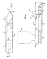
- FIG. 3 there is illustrated the reclaiming apparatus 16 in which sand is reclaimed by being maintained in a treatment temperature range in the presence of a combustion supporting gas.
- the apparatus 10 comprises a series of connected fluid bed sections 51, 52 and 53 and a hopper 54 to which sand to be reclaimed is fed.
- the sand in the present example is fed from a shake or knock-out station 14 of the magnesium alloy foundry casting plant at such a rate that the sand is only slightly above ambient temperature.
- the sand may be fed in such a way, or stored in the hopper 54 for such a period, that it is at ambient temperature on leaving the hopper 54.
- the sand may be delivered, for example, from a ferrous casting plant knock-out at such a rate and temperature and the reclaiming apparatus 16 operated at such a rate that the sand leaving the hopper 54 is at a temperature in the treatment temperature range.
- operating conditions may be such that the sand is at a temperature lying between ambient or substantially ambient temperature and the treatment temperature range.
- the sand is reduced to grain size or substantially to grain size by the shake-out or if necessary by an attrition unit, crushing unit or other means.
- Sand to be reclaimed is fed from the hopper 54 to the first fluid bed section 51 by means of a screw conveyor, air slide or other convenient controlling device.
- the sand advantageously may be fed into the fluid bed section 51 below the surface of the bed by for example a screw conveyor.
- the fluid bed section 51 contains a high density of electrical heaters 55 which heat the sand to a temperature lying in the treatment temperature range.
- the heaters 55 are preferably low voltage heaters operating at about 40-50 volts and comprising stainless steel strips through which low voltage electric heating current is passed in direct contact with the sand.
- the heaters 55 heat the sand as rapidly as possible so as to reduce smoke or other fume emission and to gain as much energy from the burning resin as possible.
- Sand is raised from slightly above ambient temperature to the treatment temperature range very rapidly in a matter of a few seconds at most in the present example.
- the first fluid bed section 51 is separated from the further fluid bed section 52 by means of a weir 56 and sand passes from the first to the second section over the top of the weir.
- sand is allowed to dwell in the treatment temperature range without further input of heat, thus allowing combustion of the organic binder to proceed in the fluidising air by utilising the heat in the sand from the first fluid bed section.
- the cooling of the sand from the fluidising air is measurable but not important in this section of the apparatus. If in any particular application supplementary heating is required in this section, the requisite number of heating elements may be provided to make up losses as necessary.
- a further fluid bed section or sections may be provided at which the sand is maintained in said treatment temperature range.
- the first and the or each further fluid bed section are thermally insulated to prevent heat loss therefrom except that heat can transfer between the first and further fluid bed sections via the weir 56.
- the third fluidised bed section 53 is thermally insulated from the previous sections by means of an insulating weir 57 and a baffle 58 and contains cooling tubes 59 which are conveniently cooled by water but may be cooled by other liquid or gas.
- the sand is cooled in this section to the desired temperature. For example, with an S0 2/ furane resin binder system the sand is cooled to a temperature in the range 30-35 0 C which is an optimum temperature for reuse with this sort of binder system.
- reclamation of the sand by combustion of the binder is completed to the required standard in the further fluid bed section.
- the method may be operated so that the reclamation is not so completed in the further fluid bed section and reclamation is completed to the required standard in the cooling fluid bed section before the temperature of the sand is reduced to below the treatment temperature range in which reclamation occurs. In all cases however, reclamation is completed to the required standard whilst the sand is fluidised.
- the sand is reclaimed to the extent that the residual binder content as measured by "Loss on Ignition" lies in the range 0.05 to 0.10% but the process may be operated with more or less reclamation so long as adequate reclamation for re-use of the sand is achieved and the term "reclaimed” is used herein to refer to such an extent of reclamation.
- the minimum extent of reclamation for re-use is a residual binder content of 0.2% but we do not want to be limited to this since, for example, some people using furane resin binder accept a higher residual binder content whilst other people using phenolic resin binder insist on a lower residual binder content than 0.05%.
- sand For the recoating of phenolic resins on shell sands the temperatures may lie in the range I20-150°C at the discharge from the cooling or third section 53. In this latter case air cooling in at least some of the cooling tubes may be desirable or the water cooling section reduced in size for the number or water cooling tubes reduced.
- the sand exits from the third fluidised bed section 53 via a discharge tube 60.
- the three fluid bed sections are separated by weirs, if desired they may be separated by other means such as separating plates having one or more openings therein or may be completely independent bed sections connected by ducts. Alternatively, the sections may not be separated by any physical barrier; each section being functionally defined.
- the first section may comprise a part of a single fluid bed having a high density of heater elements, the second section by a part of the fluid bed having no or a lower density of heating elements than in the first section and a cooling section, when provided, by a part of the bed which may have cooling elements.
- Hot dusty gas is exhausted via ducts 61, 62 and is passed through a dust extraction system, not shown, prior to exhausting to atmosphere.
- Fluidising gas in the present example air, is provided to all three sections through a plurality of discrete openings which are provided with shield means to shield the openings from ingress of sand.
- the openings may be provided for example in a plurality of tubes immersed in the sand and to which fluidising gas is fed.
- the fluidising gas may be provided by means of spurge tubes or by means of a porous bottom to the sections for example a gas permeable material, a foraminous plate or mesh.
- the above described apparatus is used to carry out a method of reclaiming used foundry sand which comprises, in the present example, feeding sand to be reclaimed into the hopper 54 and then from the hopper 54 into the first fluidised bed section 5I.
- the sand to be reclaimed is heated in the first fluidised bed section 51 to a treatment temperature range in which reclamation occurs.
- This range may be 450°C to 600°C.
- the temperature may be anywhere in the range 250°C to 500°C, preferably in the range 300°C to below 400°C and more preferably in the range 400°C to 500 C.
- the sand in the second fluid bed section 52 may be at the same temperature as in the first fluid bed section or at a lower temperature but still within the above mentioned treatment temperature range.
- the apparatus described with reference to Figures I and 2 may be made, for example, of mild steel as it does not have to withstand high temperatures.
- the electrical heaters are required to be made of a suitable high temperature material since these run at temperatures of up to 800°C.
- the electrical heaters may comprise instead of the above described low voltage heaters, conventional electric heaters operating at high voltage alternating current, i.e. a heating element within a tube so as to be electrically insulated from the sand. Electrical heating of the bed is useful to achieve simple control and to ensure that all the available oxygen in the air is available for burning the organic binder (and not the added fuel as is the case for a fuel fired bed):
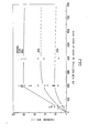
- FIG 6 shows the rates of reclamation at a below optimum flow rate of air of only 400 1/min/m 2 .
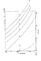
- the time temperature transformation (TTT) curve for a residual organic binder content of 0.2% indicates a useful working level at which reclamation is adequate for many processes, i.e. the sand is satisfactory for reuse.
- TTT time temperature transformation
- a time of 60 minutes is necessary to adequately reclaim sand at 400°C.
- the time required is thirteen minutes. This time lengthens to eighteen minutes as cooling becomes noticeable at 4000 l/min/m2 as shown in Figure 8.
- the sand may be reclaimed at a treatment station 16 comprising a single fluid bed at which the sand is fluidised at a temperature in the treatment temperature range and heating elements may be provided at only the entry end of the bed or throughout the length of the bed at a uniform distribution or a non-uniform distribution so as to cause the temperature in the bed to decrease towards the exit end thereof.
- the sand may be fed from the treatment station at elevated temperature without passing through a cooling fluidised bed section.
- Compositions herein are expressed in % by weight.
Landscapes
- Engineering & Computer Science (AREA)
- Mechanical Engineering (AREA)
- Molds, Cores, And Manufacturing Methods Thereof (AREA)
Applications Claiming Priority (4)
| Application Number | Priority Date | Filing Date | Title |
|---|---|---|---|
| GB838306492A GB8306492D0 (en) | 1983-03-09 | 1983-03-09 | Casting metal and reclaiming foundry sand |
| GB8306492 | 1983-03-09 | ||
| GB838307451A GB8307451D0 (en) | 1983-03-09 | 1983-03-17 | Casting metal |
| GB8307451 | 1983-03-17 |
Publications (3)
| Publication Number | Publication Date |
|---|---|
| EP0122029A2 true EP0122029A2 (de) | 1984-10-17 |
| EP0122029A3 EP0122029A3 (en) | 1986-08-13 |
| EP0122029B1 EP0122029B1 (de) | 1988-07-27 |
Family
ID=26285455
Family Applications (1)
| Application Number | Title | Priority Date | Filing Date |
|---|---|---|---|
| EP19840301529 Expired EP0122029B1 (de) | 1983-03-09 | 1984-03-08 | Sandgiessen und Regenerieren von Giessereisand |
Country Status (3)
| Country | Link |
|---|---|
| EP (1) | EP0122029B1 (de) |
| DE (1) | DE3472906D1 (de) |
| GB (1) | GB2137114B (de) |
Cited By (7)
| Publication number | Priority date | Publication date | Assignee | Title |
|---|---|---|---|---|
| AT392928B (de) * | 1989-05-02 | 1991-07-10 | Oberleitner Rupert Dipl Ing | Verfahren und einrichtung zur thermischen regenerierung kunstharzgebundener giessereisande |
| US5189813A (en) * | 1991-02-22 | 1993-03-02 | Samuel Strapping Systems Ltd. | Fluidized bed and method of processing material |
| US5294095A (en) * | 1990-06-08 | 1994-03-15 | Bgk Finishing Systems, Inc. | Fluidized bed with submerged infrared lamps |
| US5332139A (en) * | 1990-06-08 | 1994-07-26 | Bgk Finishing Systems, Inc. | Fluidized bed apparatus and method using same |
| EP0917921A1 (de) * | 1997-11-19 | 1999-05-26 | Carmen Scherer | Verfahren und Vorrichtung zur Rückgewinnung von Kern- oder Formsand |
| US6399032B1 (en) * | 1998-08-11 | 2002-06-04 | Fata Aluminium Division Of Fata Group Spa | Plant for continuously regenerating foundry sand and associated method |
| GB2394684A (en) * | 2001-04-05 | 2004-05-05 | Clayton Thermal Processes Ltd | Reclamation treatment of bonded particulates |
Families Citing this family (9)
| Publication number | Priority date | Publication date | Assignee | Title |
|---|---|---|---|---|
| KR100263975B1 (ko) † | 1992-08-13 | 2000-09-01 | 스콧 피. 크래프턴 | 금속 주물의 열처리 및 노 내부 주물사 재생 방법 및 장치 |
| AU2190497A (en) * | 1996-02-23 | 1997-09-10 | Consolidated Engineering Company, Inc. | System and process for reclaiming sand |
| US6217317B1 (en) | 1998-12-15 | 2001-04-17 | Consolidated Engineering Company, Inc. | Combination conduction/convection furnace |
| US6336809B1 (en) | 1998-12-15 | 2002-01-08 | Consolidated Engineering Company, Inc. | Combination conduction/convection furnace |
| US6622775B2 (en) | 2000-05-10 | 2003-09-23 | Consolidated Engineering Company, Inc. | Method and apparatus for assisting removal of sand moldings from castings |
| JP2005532911A (ja) | 2002-07-11 | 2005-11-04 | コンソリデイテッド エンジニアリング カンパニー, インコーポレイテッド | 鋳造物からの砂鋳型の除去を補助するための方法および装置 |
| WO2004009855A1 (en) | 2002-07-18 | 2004-01-29 | Consolidated Engineering Company, Inc. | Method and system for processing castings |
| WO2005089981A1 (en) * | 2004-03-19 | 2005-09-29 | Consolidated Engineering Company, Inc. | System for heat treating castings and reclaiming sand |
| US20060103059A1 (en) | 2004-10-29 | 2006-05-18 | Crafton Scott P | High pressure heat treatment system |
Family Cites Families (11)
| Publication number | Priority date | Publication date | Assignee | Title |
|---|---|---|---|---|
| GB727286A (en) * | 1952-01-23 | 1955-03-30 | Aluminium Lab Ltd | Zoning device for horizontal fluo-solid beds |
| US3212144A (en) * | 1962-06-22 | 1965-10-19 | Frank R Capps | Sand molds for metal casting and methods therefor |
| GB1012575A (en) * | 1963-05-25 | 1965-12-08 | British Cast Iron Res Ass | Improvements in the conditioning of granular or pulverulent materials |
| US3480265A (en) * | 1968-01-04 | 1969-11-25 | Vagn Deve | Shell sand treating apparatus and method |
| GB1293187A (en) * | 1969-11-24 | 1972-10-18 | Upper Canada Mfg Ltd | Improvements relating to the treatment of granular material |
| US3685165A (en) * | 1970-10-12 | 1972-08-22 | Combustion Eng | Thermal sand reclamation unit |
| PL87921B1 (de) * | 1974-03-04 | 1976-07-31 | Przedsiebiorstwo Projektowaniapo | |
| GB1532244A (en) * | 1976-09-29 | 1978-11-15 | Marwin Ltd | Heat exchange units |
| US4508277A (en) * | 1980-09-08 | 1985-04-02 | Andrews Robert S L | Apparatus for reclaiming foundry sand |
| GB2091148A (en) * | 1980-12-16 | 1982-07-28 | Cosworth Research Dev Ltd | Method of and apparatus for treating granular material |
| IT1155658B (it) * | 1982-03-23 | 1987-01-28 | Fata Ind Spa | Sistema e metodo per il recupero delle sabbie contenute in forme ed anime di fonderia mediante calcinazione in un forno a letto fluidizzato |
-
1984
- 1984-03-08 GB GB08406118A patent/GB2137114B/en not_active Expired
- 1984-03-08 DE DE8484301529T patent/DE3472906D1/de not_active Expired
- 1984-03-08 EP EP19840301529 patent/EP0122029B1/de not_active Expired
Cited By (8)
| Publication number | Priority date | Publication date | Assignee | Title |
|---|---|---|---|---|
| AT392928B (de) * | 1989-05-02 | 1991-07-10 | Oberleitner Rupert Dipl Ing | Verfahren und einrichtung zur thermischen regenerierung kunstharzgebundener giessereisande |
| US5294095A (en) * | 1990-06-08 | 1994-03-15 | Bgk Finishing Systems, Inc. | Fluidized bed with submerged infrared lamps |
| US5332139A (en) * | 1990-06-08 | 1994-07-26 | Bgk Finishing Systems, Inc. | Fluidized bed apparatus and method using same |
| US5189813A (en) * | 1991-02-22 | 1993-03-02 | Samuel Strapping Systems Ltd. | Fluidized bed and method of processing material |
| EP0917921A1 (de) * | 1997-11-19 | 1999-05-26 | Carmen Scherer | Verfahren und Vorrichtung zur Rückgewinnung von Kern- oder Formsand |
| US6399032B1 (en) * | 1998-08-11 | 2002-06-04 | Fata Aluminium Division Of Fata Group Spa | Plant for continuously regenerating foundry sand and associated method |
| GB2394684A (en) * | 2001-04-05 | 2004-05-05 | Clayton Thermal Processes Ltd | Reclamation treatment of bonded particulates |
| GB2394684B (en) * | 2001-04-05 | 2004-11-03 | Clayton Thermal Processes Ltd | Reclamation treatment of bonded particulates |
Also Published As
| Publication number | Publication date |
|---|---|
| GB2137114A (en) | 1984-10-03 |
| GB8406118D0 (en) | 1984-04-11 |
| GB2137114B (en) | 1986-12-17 |
| EP0122029B1 (de) | 1988-07-27 |
| EP0122029A3 (en) | 1986-08-13 |
| DE3472906D1 (en) | 1988-09-01 |
Similar Documents
| Publication | Publication Date | Title |
|---|---|---|
| EP0122029B1 (de) | Sandgiessen und Regenerieren von Giessereisand | |
| EP0183761B1 (de) | Giessen von metallgegenständen | |
| EP0132493B1 (de) | Vorrichtung und Verfahren zur Regenerierung von gebrauchtem Giessereisand | |
| EP1551578B1 (de) | Verfahren zum erwärmen von giessformen | |
| US4222429A (en) | Foundry process including heat treating of produced castings in formation sand | |
| CA1233964A (en) | Method of reclaiming sand used in evaporative casting process | |
| RU2001120717A (ru) | Устройство для непрерывного подогрева, плавления, рафинирования и разливки стали и способ непрерывного подогрева, плавления, рафинирования и разливки стали | |
| US4804032A (en) | Method of making metal castings | |
| SK283412B6 (sk) | Spôsob výroby polotovaru na metalurgické spracovanie a lejárske zariadenie na jeho výrobu | |
| EP0025818A1 (de) | Verfahren zum Giessen von Schalenformen | |
| EP0234877B1 (de) | Verfahren und Vorrichtung zum Giessen | |
| JPS59193210A (ja) | 鋼の製造方法及び装置 | |
| GB2159445A (en) | Low-pressure, upward casting of metal articles | |
| CA1296863C (en) | Casting metal and reclaiming foundry sand | |
| EP0099470A1 (de) | Giessen von Nichteisen-Metallen | |
| EP0562170B1 (de) | Differentialdruck-Gegenschwerkraftgiessen | |
| CA1078132A (en) | Method of making ductile iron treating agents | |
| US3080628A (en) | Method of and a mold and ingate system for casting metals | |
| JPS63268559A (ja) | スライデイングゲ−ト | |
| Alting et al. | Liquid Materials: Casting Processes | |
| US627835A (en) | Apparatus for casting and heating ingots. | |
| SU971910A1 (ru) | Устройство дл модифицировани расплавленного металла в литейной форме | |
| CA1267266A (en) | Casting of metal articles | |
| JPS6347402Y2 (de) | ||
| SU768537A1 (ru) | Автоматизированна лини дл получени отливок |
Legal Events
| Date | Code | Title | Description |
|---|---|---|---|
| PUAI | Public reference made under article 153(3) epc to a published international application that has entered the european phase |
Free format text: ORIGINAL CODE: 0009012 |
|
| AK | Designated contracting states |
Designated state(s): BE CH DE FR IT LI NL SE |
|
| PUAL | Search report despatched |
Free format text: ORIGINAL CODE: 0009013 |
|
| AK | Designated contracting states |
Kind code of ref document: A3 Designated state(s): BE CH DE FR IT LI NL SE |
|
| 17P | Request for examination filed |
Effective date: 19861020 |
|
| 17Q | First examination report despatched |
Effective date: 19870520 |
|
| GRAA | (expected) grant |
Free format text: ORIGINAL CODE: 0009210 |
|
| AK | Designated contracting states |
Kind code of ref document: B1 Designated state(s): BE CH DE FR IT LI NL SE |
|
| PG25 | Lapsed in a contracting state [announced via postgrant information from national office to epo] |
Ref country code: NL Effective date: 19880727 Ref country code: LI Effective date: 19880727 Ref country code: CH Effective date: 19880727 Ref country code: BE Effective date: 19880727 |
|
| REF | Corresponds to: |
Ref document number: 3472906 Country of ref document: DE Date of ref document: 19880901 |
|
| ITF | It: translation for a ep patent filed | ||
| REG | Reference to a national code |
Ref country code: CH Ref legal event code: PL |
|
| ET | Fr: translation filed | ||
| NLV1 | Nl: lapsed or annulled due to failure to fulfill the requirements of art. 29p and 29m of the patents act | ||
| PLBE | No opposition filed within time limit |
Free format text: ORIGINAL CODE: 0009261 |
|
| STAA | Information on the status of an ep patent application or granted ep patent |
Free format text: STATUS: NO OPPOSITION FILED WITHIN TIME LIMIT |
|
| 26N | No opposition filed | ||
| ITTA | It: last paid annual fee | ||
| EAL | Se: european patent in force in sweden |
Ref document number: 84301529.8 |
|
| PGFP | Annual fee paid to national office [announced via postgrant information from national office to epo] |
Ref country code: SE Payment date: 20030306 Year of fee payment: 20 |
|
| PGFP | Annual fee paid to national office [announced via postgrant information from national office to epo] |
Ref country code: FR Payment date: 20030310 Year of fee payment: 20 |
|
| PGFP | Annual fee paid to national office [announced via postgrant information from national office to epo] |
Ref country code: DE Payment date: 20030320 Year of fee payment: 20 |
|
| EUG | Se: european patent has lapsed |