EP0122100B1 - Mesure de la densité et du débit massique d'un fluide - Google Patents
Mesure de la densité et du débit massique d'un fluide Download PDFInfo
- Publication number
- EP0122100B1 EP0122100B1 EP84302220A EP84302220A EP0122100B1 EP 0122100 B1 EP0122100 B1 EP 0122100B1 EP 84302220 A EP84302220 A EP 84302220A EP 84302220 A EP84302220 A EP 84302220A EP 0122100 B1 EP0122100 B1 EP 0122100B1
- Authority
- EP
- European Patent Office
- Prior art keywords
- fluid
- fuel
- density
- oscillator
- conduit
- Prior art date
- Legal status (The legal status is an assumption and is not a legal conclusion. Google has not performed a legal analysis and makes no representation as to the accuracy of the status listed.)
- Expired
Links
- 239000012530 fluid Substances 0.000 title claims description 44
- 238000005259 measurement Methods 0.000 title description 4
- 239000000446 fuel Substances 0.000 claims description 102
- 239000007788 liquid Substances 0.000 claims description 12
- 238000000034 method Methods 0.000 claims description 11
- 230000001105 regulatory effect Effects 0.000 claims description 5
- 230000001276 controlling effect Effects 0.000 claims description 3
- 238000012544 monitoring process Methods 0.000 claims description 2
- 238000009877 rendering Methods 0.000 claims description 2
- 230000004044 response Effects 0.000 claims description 2
- 230000001419 dependent effect Effects 0.000 claims 4
- 239000002131 composite material Substances 0.000 claims 1
- 230000003993 interaction Effects 0.000 description 8
- 238000011144 upstream manufacturing Methods 0.000 description 5
- 238000004519 manufacturing process Methods 0.000 description 3
- 238000010276 construction Methods 0.000 description 2
- 239000002184 metal Substances 0.000 description 2
- 230000010355 oscillation Effects 0.000 description 2
- 230000010349 pulsation Effects 0.000 description 2
- 230000001133 acceleration Effects 0.000 description 1
- 230000008901 benefit Effects 0.000 description 1
- 230000005540 biological transmission Effects 0.000 description 1
- 230000008859 change Effects 0.000 description 1
- 150000001875 compounds Chemical class 0.000 description 1
- 230000006835 compression Effects 0.000 description 1
- 238000007906 compression Methods 0.000 description 1
- 238000007796 conventional method Methods 0.000 description 1
- 238000010586 diagram Methods 0.000 description 1
- 238000006073 displacement reaction Methods 0.000 description 1
- 230000000694 effects Effects 0.000 description 1
- 229920006333 epoxy cement Polymers 0.000 description 1
- 230000000704 physical effect Effects 0.000 description 1
- 238000004382 potting Methods 0.000 description 1
- 230000008569 process Effects 0.000 description 1
- 238000007789 sealing Methods 0.000 description 1
- 238000012546 transfer Methods 0.000 description 1
Images

Classifications
-
- G—PHYSICS
- G05—CONTROLLING; REGULATING
- G05D—SYSTEMS FOR CONTROLLING OR REGULATING NON-ELECTRIC VARIABLES
- G05D7/00—Control of flow
- G05D7/06—Control of flow characterised by the use of electric means
- G05D7/0617—Control of flow characterised by the use of electric means specially adapted for fluid materials
- G05D7/0629—Control of flow characterised by the use of electric means specially adapted for fluid materials characterised by the type of regulator means
- G05D7/0688—Control of flow characterised by the use of electric means specially adapted for fluid materials characterised by the type of regulator means by combined action on throttling means and flow sources
-
- G—PHYSICS
- G01—MEASURING; TESTING
- G01N—INVESTIGATING OR ANALYSING MATERIALS BY DETERMINING THEIR CHEMICAL OR PHYSICAL PROPERTIES
- G01N9/00—Investigating density or specific gravity of materials; Analysing materials by determining density or specific gravity
- G01N9/002—Investigating density or specific gravity of materials; Analysing materials by determining density or specific gravity using variation of the resonant frequency of an element vibrating in contact with the material submitted to analysis
-
- Y—GENERAL TAGGING OF NEW TECHNOLOGICAL DEVELOPMENTS; GENERAL TAGGING OF CROSS-SECTIONAL TECHNOLOGIES SPANNING OVER SEVERAL SECTIONS OF THE IPC; TECHNICAL SUBJECTS COVERED BY FORMER USPC CROSS-REFERENCE ART COLLECTIONS [XRACs] AND DIGESTS
- Y10—TECHNICAL SUBJECTS COVERED BY FORMER USPC
- Y10S—TECHNICAL SUBJECTS COVERED BY FORMER USPC CROSS-REFERENCE ART COLLECTIONS [XRACs] AND DIGESTS
- Y10S73/00—Measuring and testing
- Y10S73/08—Fluid circuits
-
- Y—GENERAL TAGGING OF NEW TECHNOLOGICAL DEVELOPMENTS; GENERAL TAGGING OF CROSS-SECTIONAL TECHNOLOGIES SPANNING OVER SEVERAL SECTIONS OF THE IPC; TECHNICAL SUBJECTS COVERED BY FORMER USPC CROSS-REFERENCE ART COLLECTIONS [XRACs] AND DIGESTS
- Y10—TECHNICAL SUBJECTS COVERED BY FORMER USPC
- Y10T—TECHNICAL SUBJECTS COVERED BY FORMER US CLASSIFICATION
- Y10T137/00—Fluid handling
- Y10T137/0318—Processes
- Y10T137/0324—With control of flow by a condition or characteristic of a fluid
- Y10T137/0357—For producing uniform flow
-
- Y—GENERAL TAGGING OF NEW TECHNOLOGICAL DEVELOPMENTS; GENERAL TAGGING OF CROSS-SECTIONAL TECHNOLOGIES SPANNING OVER SEVERAL SECTIONS OF THE IPC; TECHNICAL SUBJECTS COVERED BY FORMER USPC CROSS-REFERENCE ART COLLECTIONS [XRACs] AND DIGESTS
- Y10—TECHNICAL SUBJECTS COVERED BY FORMER USPC
- Y10T—TECHNICAL SUBJECTS COVERED BY FORMER US CLASSIFICATION
- Y10T137/00—Fluid handling
- Y10T137/206—Flow affected by fluid contact, energy field or coanda effect [e.g., pure fluid device or system]
- Y10T137/2229—Device including passages having V over T configuration
- Y10T137/2234—And feedback passage[s] or path[s]
-
- Y—GENERAL TAGGING OF NEW TECHNOLOGICAL DEVELOPMENTS; GENERAL TAGGING OF CROSS-SECTIONAL TECHNOLOGIES SPANNING OVER SEVERAL SECTIONS OF THE IPC; TECHNICAL SUBJECTS COVERED BY FORMER USPC CROSS-REFERENCE ART COLLECTIONS [XRACs] AND DIGESTS
- Y10—TECHNICAL SUBJECTS COVERED BY FORMER USPC
- Y10T—TECHNICAL SUBJECTS COVERED BY FORMER US CLASSIFICATION
- Y10T137/00—Fluid handling
- Y10T137/7722—Line condition change responsive valves
- Y10T137/7758—Pilot or servo controlled
- Y10T137/7759—Responsive to change in rate of fluid flow
Definitions
- the present invention relates generally to the measurement of density and mass flow rate of a fluid, for example a fuel supplied to a jet propulsion engine.
- volumetric flow can be measured with acceptable accuracy by any of several conventional flow meters, including turbine, differential pressure, positive displacement, ultrasonic orfluidic devices.
- methods of measuring the fuel's density are inaccurate.
- a "true" mass flowmeter may use a motor driven or fuel-driven impeller which imparts angular momentum to the fuel at a rate proportional to the fuel's mass flow rate.
- the fuel is then caused to flow through an indentical turbine which is restrained by a spring against rotation.
- By electronically measuring the angular deflection of the turbine the mass flow rate of the fuel is directly obtained.
- a fluid density measuring apparatus comprises a fluid oscillator, means for maintaining the pressure drop across the power nozzle of the oscillator essentially constant, and means responsive to the frequency of the oscillator for giving a signal related to the fluid density.
- the frequency of the oscillator is closely related to the density of the working fluid in the oscillator, and that means that however the particular characteristics of a fluid can vary from batch to batch, or with temperature, or by substituting one fuel for another, the oscillator can be arranged always to give a signal accurately representing the density of the fuel.
- the invention is basically an apparatus and a method for determining the density of fluid, it can be extended to an apparatus and method for measuring and indeed contolling the mass flow rate of the fluid in a conduit.
- the fluid used as the working fluid in the fluidic oscillator can be bled off from the conduit, and after leaving the fluidic oscillator returned to the conduit upstream of a fluid pump.
- mass flow rate control can be used for controlling the mass flow rate of fluids in different applications, it will be clear from the preceding remarks that a particular application is the control of the mass fuel supply rate to jet aircraft engines, because there can then be automatic compensation for variations in the temperature and precise content of the particular fuel used.
- the fluidic oscillator is comparatively cheap to manufacture while still having high accuracy, and is also simple and rugged, and one advantage of the use of a fluidic oscillator for this purpose is that two different frequency signals can be derived from different feedback paths in two parts of the oscillator to produce a combined frequency or density signal which can be compensated for vibrations and acceleration loads by mounting two different transducers in such a way that vibration effects act on them equally and in opposite senses.
- Another aspect of the invention is a method of regulating the mass flow rate of fuel received by an engine through a supply conduit, in which a portion of the fuel is used as the fluid supplied to the power nozzle of a fluidic oscillator which generates a first output signal indicative of the density of such fuel a pressure regulator maintains a predetermined constant pressure drop across the power nozzle;
- a second output signal is generated indicative of the volumetric rate of fuel flow through the supply conduit; and the mass flow rate of fuel received by the engine through the supply conduit is regulated using the first and second output signals.
- apparatus for monitoring the mass flow rate of a liquid flowing through a supply conduit comprises a fluidic oscillator having a power nozzle for receiving at least a portion of the fluid flow through the supply conduit, and responsively generating a first output signal indicative of the density of the flowing fluid; a pressure regulator for maintaining the pressure drop across said power nozzle and rendering the magnitude of the said first output signal substantially insensitive to variations in the physical characteristics of the flowing fluid; means for generating a second output signal indicative of the volumetric liquid flow rate through the supply conduit; and means for receiving said first and second output signals and generating a signal indicative of the liquid mass flow rate through the supply conduit.
- the present invention provides an inferential fuel mass flow rate measuring and control system which separately measures the volumetric flow rate and the density of fuel being supplied to a gas turbine aircraft propulsion engine.
- the sensed volumetric flow rate and density values are automatically multiplied to generate a signal indicative of the fuel mass flow rate.
- This signal is transmitted to the engine's fuel control computer which responsively controls the actual mass flow rate of fuel to the engine in accordance with a desired supply flow rate.
- the density-sensing portion of the system comprises fluidic oscillator means which receive and are powered by a portion of the fuel supplied to the engine to create in the oscillator means pulsating pressure signals whose frequencies are indicative of the density of the received fuel.
- pressure control means which function to automatically maintain the fuel's pressure drop across the oscillator mean's internal power nozzle at an essentially constant level.
- the density sensing portion of the system employs fluidic apparatus, the high degree of measurement accuracy of the system is achieved with condiderably less manufacturing expense that in the case of conventional true mass flow meter systems. Moreover, the inherent simplicity and ruggedness of fluidic control apparatus considerably enhances the reliability of the system.
- the fluidic oscillator means are provided with a duality of pressure-to-electric transducer means which convert the oscillator means' pulsating pressure outputs to an oscillating electrical signal having a frequency indicative of the sensed fuel density.
- the tranducer means are connected to the oscillator means in a mutually opposite polarity relationship to thereby substantially eliminate output a signal error caused by any mechanical vibration to which the oscillator means may be subjected during operation of the system.
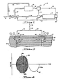
- FIG. 1 Schematically illustrated in Figure 1 is an inferential fuel mass flow rate measuring and control system 10 which embodies principles of the present invention and is utilized in conjunction with a gas turbine aircraft propulsion engine 12.
- fuel from a source thereof (not shown) is supplied to the engine by a pump 14, via a main supply conduit 16, through a throttling valve 18.
- the system 10 comprises a fuel density sensing portion 20, a volumetric flow sensing portion in the form of a conventional turbine flowmeter 22 positioned in conduit 16 between the engine 12 and valve 18, an electronic signal processor 24, and a fuel control computer 26 operatively associated with the engine 12.
- the density sensor 20 receives and is powered by a small flow of fuel supplied thereto by branch supply conduit 28 connected to the main conduit 16 between the pump 14 and the valve 18. Fuel supplied to density sensor 20 is returned to the main conduit 16 upstream of pump 14 by a small return conduit 30.
- the density sensor 20 During operation of the system 10, the density sensor 20 generates an electrical output signal 32 indicative of the density of the fuel received by engine 12, while the flowmeter 22 generates an electrical output signal 34 indicative of the volumetric flow of fuel to the engine 12.
- the signal processor 24 receives the density and volumetric flow output signals 32, 34, automatically multiplies the two signals, and responsively transmits to the fuel control computer 26 an input signal 36 which is precisely indicative of the actual mass flow rate of fuel received by engine 12 via the supply conduits 16.
- the fuel control computer 26 compares the value of mass flow rate signal 36 to a control input signal 38 representing a desired fuel mass inflow rate and responsively makes any necessary adjustments to the engine fuel inflow by automatically adjusting the throttling valve 18 by means of a value positioning signal 39 generated by the computer.
- the system 10 is essentially insensitive to variations in the physical characteristics of the fuel being supplied to engine 12. More specifically, despite variations in the temperature, pressure or viscosity of a particular fuel being used, or variations in the type of fuel used, a high degree of accuracy of the mass flow signal 36, and thus of the entire system 10, is maintained. This highly desirable feature of the system is achieved by virtue of the unique structure and operation of the fluid density sensor 20 which will now be described with reference to Fig. 2.
- the density sensor 20 comprises two operatively associated components-a fluidic oscillator 40 and a fluid pressure regulator 42.
- the fluidic oscillator 40 is of a generally conventional laminated construction, having a monolithic body consisting of a multiplicity of thin, rectangular metal laminae mutually bonded together in an edge-aligned relationship.
- such laminae comprise an upper end lamina 44, a central or main lamina 46, a series of upper auxiliary laminae 48 positioned between laminae 44 and 46, a lower end lamina 50, and a series of lower auxiliary laminae 52 positioned between laminae 46 and 50.
- Auxiliary laminae each have suitable openings formed therein (not all of which are illustrated in Fig. 2) which, in a conventional manner, collectively define various internal passages within the oscillator body leading to and from the main lamina 46.
- One such passage is a supply passage 54 which extends downwardly through upper end lamina 44 and each of the auxiliary laminae 48 adjacent the left corner of the oscillator body.
- supply passage 54 is positioned directly above a supply channel 56 formed in the main lamina 46 and extending lengthwise toward the right corner of the oscillator body. At its right end the supply channel is necked down to form a power nozzle 58 which opens at its discharge end into the left end of an elongated interaction channel 60 also formed through main lamina 46.
- the right or downstream end of the interaction channel is laterally divided by an elongated splitter portion 62 of main lamina 46 having a leading edge 64. Leading edge 64 faces and is laterally aligned with the outlet of the power nozzle 58.
- a small quantity of fuel is continuously supplied to the supply channel 56 through the supply opening 54 to which the branch supply conduit 28 is connected.
- the fuel received in supply channel 56 is forced outwardly through power nozzle 58 to thereby form a fuel jet 66 which longitudinally traverses the interaction channel 60 and impinges upon the leading splitter edge 64.
- Splitter edge 64 divides the jet 66 into two substreams 66a, 66b, which respectively flow along opposite sides of splitter 62 into a pair of main lamina receiving channels 68a, 68b extending laterally outwardly of splitter 62, on opposite sides thereof, downstream from the leading splitter edge 64.
- a pair of jet-control channels 70a, 70b which communicate at their inner ends with the interaction channel directly adjacent the outlet of power nozzle 58 and extend laterally outwardly from the interaction channel in opposite directions.
- the outer ends of channels 68a and 70a communicate through a feedback passage 72a
- the outer ends of channels 68b and 70b communicate through a feedback passage 72b. While schematically illustrated by the dashed lines directly above main lamina 46 for the sake of clarity, these feedback passages are actually positioned in the upper portion of the oscillator body, being collectively defined by various cooperating channels and passages formed through the upper auxiliary laminae 48 (similarly to the laminae openings which define inlet passage 54).
- one or the other of the substreams 66a, 66b is initially at least minutely larger in cross-section than the other substream.
- This initial unequal division of the fuel jet creates a relative pressure differential between the receiving channels 68a, 68b.
- the fluid pressure in receiving channel 68a is slightly larger than the corresponding pressure in receiving channel 68b.
- This pressure differential between the receiving channels 68a, 68b is imposed upon the jet-control channels 70a, 70b via the feedback channels 72a, 72b, respectively, with the fluid pressure in channel 70a being initially greater than that in channel 70b.
- channels 70a, 70b which communicate at their inner ends with interaction channel 60 on opposite sides of the fuel jet 66
- the fluid pressure imbalance between channels 70a, 70b causes the jet 66 to pivot slightly in a clockwise direction (as viewed in Fig. 2) relative to the splitter edge 64.
- Such pivoting of the fuel jet increases the cross-sectional area of substream 66b relative to that of substream 66a thereby reversing the pressure differential between receiving channels 68a, 68b.
- This reversal via feedback channels 72a, 72b, reverses the pressure differential between channels 70a, 70b, causing a counterclockwise pivoting of the fuel jet, again reversing the pressure differential between receiving channels 68a, 68b.
- the above-described pressure reversal cycle causes the fuel jet 66 to continuously and very rapidly oscillate from side to side as indicated by the double-ended arrow 72 in Fig. 2.
- such jet oscillation creates fluid pressure pulsations in each of the feedback channels 72a, 72b.
- the frequency of such oscillations can be very precisely indicative of the density of the fuel ultimately supplied to the engine 12, by use of the method described below.
- transducers 74, 76 are respectively recessed within slightly larger diameter circular openings 84, 86 formed through the upper density senor lamina 44.
- the bottom end of each transducer rests upon a thin metal diaphragm plate 88 sandwiched between the upper lamina 44 and the uppermost auxiliary lamina 48.
- a conventional potting compound 90 is used to secure and seal the transducers within the lamina openings 84, 86.
- circular recesses 92, 94 Directly beneath the diaphragn 88 are circular recesses 92, 94, which are formed in the uppermost auxiliary lamina 48, such recesses being respectively aligned with and generally of the same diameter as the transducer openings 84, 86.
- Recesses 92, 94 respectively communicate with the internal feedback passages 72a, 72b, via vertically extending pressure transmission passages 96, 98 (see also Figure 2) defined within the upper auxiliary laminae 48.
- Transducers 74, 76 are bonded to the diaphragm 88 (with a conventional conductive epoxy cement) in a mutually opposite polarity relationship, with the negative end of transducer 74 and the positive end of transducer 76 abutting the diaphragm.
- This opposite polarity transducer connection causes the density sensor output signal 32 to assume the sinusoidal configuration indicated in Figure 4-the positive half 32a of the sine wave being attributable to transducer 74 and the negative half 32b being attributable to transducer 76.
- Such opposite polarity connection of the transducers also renders the density sensor substantially totally insensitive to mechanical vibration in the following manner.
- the diaphragm portions beneath lamina openings 84, 86 will be subjected to oscillating vertical flexure (as viewed in Figure 3) such that at the same instant each transducer will be flexed either upwardly or downwardly.
- Upward vibrational flexure (for example) of transducer 74 adds a false signal or vibrational "noise" 96a to a portion 32a or output signal 32.
- transducer 76 produces in the common lead 82 an identically configured false signal 96b which is of opposite polarity relative to noise signal 96a, thereby cancelling it out completely and leaving the transducer output signal portion 32a, (or signal portion 32b as the case may be) undistorted by vibrational noise.
- the density sensing portion 20 ( Figure 1) of system 10 is uniquely unaffected by variations in the physical characteristics of the fuel being supplied to the engine 12 via conduit 16. More specifically, in the present invention the density-indicative output signal 32 retains its high degree of accuracy despite variations in the temperature, pressure and/or viscosity of the supplied fuel.
- the pressure regulator 42 has a hollow, open-ended, cylindrical body 98.
- an end cap 100 is secured (by means not illustrated in Fig. 2), a seal between the body and cap 98, 100 being provided by an O-ring 102 positioned therebetween.
- an end cap 104 is similarly secured and sealed with an O-ring 106.
- a hollow central portion 108 of cap 104 projects axially outwardly from the remainder of the cap and, in turn, has a hollow, outwardly projecting central stem portion 110.
- Valve member 132 having mutually spaced opposite end portion 134,136 is slidably received within the liner 112 for axial movement relative thereto.
- Valve member 132 defines with the regulator liner and end caps, from left to right within the regulator, a chamber 138 adjacent end cap 100, an annular chamber 140 between the value end portions 134,136, and a chamber 142 adjacent end cap 104.
- Valve member 132 is biased leftwardly toward engagement with end cap 100 by means of a frustoconically shaped compression spring 144 positioned within chamber 142 and extending axially into the open valve end portion 136.
- Spring 144 bears at its base end against the rightwardly facing inner end surface of value end portion 136, with the opposite end of the spring being seated on a grooved flange 146 carried on the inner end of an adjusting bolt 148.
- Bolt 148 extends outwardly through the cap stem 110, and slidably engages the interior surface thereof by means of annularly flanged central portion 150 of the bolt upon which is mounted an appropriate 0-ring seal 152.
- a threaded outer end portion 154 of the bolt is received in a threaded opening 156 formed through the outer end of stem 110 with the outer end of the bolt projecting rightwardly of the stem.
- This construction permits the biasing force of spring 144 to be adjusted simply by tightening or loosening the bolt 148. After adjustment of such biasing force in this manner, the bolt may be locked into position by means of a lock washer 158 and nut 160 on its outer end.
- the pressure regulator 42 functions to regulate the pressure drop across the oscillator power nozzle 58 by receiving and utilizing two fuel pressure signals-the first signal being indicative of the fuel pressure upstream from the nozzle, and the second signal being indicative of the fuel fet pressure downstream from the nozzle.
- the first signal is transmitted to the regulator via a branch conduit 162 (Fig. 2) interconnected between fuel supply conduit 28, just upstream of oscillator inlet 54, and an inlet passage 164 formed in the regulator body 98.
- Inlet 164 opens into the annular regulator chamber 120 which communicates with the valve chamber 138 via a recess 166 formed in the inner surface of the end cap 100. Fuel entering regulator inlet 164 is forced via chamber 120 and recess 166 into the valve chamber 138 where it exerts a rightward force on valve 132 which is resisted by the preset biasing force of spring 144.
- the second fuel pressure indicative signal is transmitted to the regulator through an outlet conduit 168 interconnected between the oscillator 40 and the regulator. All of the fuel supplied to the oscillator through its inlet 54 is ultimately forced into conduit 168 via vent passages 170, 172, 174, 176 formed in the main oscillator lamina 46 and extending laterally from the interaction channel 60 between the jet-control channels 70a, 70b and the receiving channels 68, 68b. At their outer ends these vent passages are extended downwardly into the lower auxiliary laminae 52 where they are interconnected into an oscillator outlet passage (not shown in Fig. 2), the outlet passage in turn being connected to the upstream end of conduit 168.
- the downstream end of conduit 168 is connected to an inlet 178 formed in the regulator body. Inlet 178 communicates with an inlet passage 180 which extends between the annular chamber 122 and the regulator chamber 142.
- the pressure of the fuel entering inlet 178 is indicative of the discharge pressure of the oscillator power nozzle 58.
- a portion of the fuel entering inlet 178 flows leftwardly through passage 180 into the annular chamber 122 and then into the annular chamber 140 through a series of small metering ports 182 extending through the liner 112. From chamber 140 the fuel flows outwardly through a series of transfer ports 184 formed through liner 112 and into the annular chamber 124. It then flows outwardly through a regulator outlet passage 186 to which is connected the fuel return conduit 30.
- a portion of the fuel entering regulator inlet 178 (Fig. 2) is also forced rightwardly through passage 180, across an orifice 188, and into the regulator chamber 142 wherein the fuel is trapped and exerts a leftward pressure force upon the value 132.
- This force is supplemented by the force of spring 144 and opposed by the pressure force of the fuel within chamber 138 (the pressure in chamber 138 being, of course, higher than the pressure in chamber 142).
- the spring force is pre-adjusted (with bolt 148) so that when the pressure drop across nozzle 58 is at its setpoint level the valve 132 is moved slightly rightwardly from its "at rest" position indicated in solid lines in Fig. 2.
- valve member is forced rightwardly to a normal operation position in which the back end surface 190 of value end 134 is moved across a portion of the metering orifices 182 (as indicated by the dashed line 190). In this position valve end 134 partially blocks such orifices, thereby restricting the flow of fuel therethrough.
- valve member 132 will be automatically moved to increase or decrease its restriction of the metering ports 182 thereby changing the pressure differential between conduits 162, 168 and bringing the nozzle pressure drop back to its predetermined setpoint level.
- the present invention provides an inferential fuel measuring and control system which eliminates or minimises the inaccuracies present in conventional inferential systems. Importantly, this very desirable result is achieved without the relatively high costs typically associated with "direct" measuring systems.
Landscapes
- Physics & Mathematics (AREA)
- General Physics & Mathematics (AREA)
- Engineering & Computer Science (AREA)
- Automation & Control Theory (AREA)
- Health & Medical Sciences (AREA)
- Life Sciences & Earth Sciences (AREA)
- Chemical & Material Sciences (AREA)
- Analytical Chemistry (AREA)
- Biochemistry (AREA)
- General Health & Medical Sciences (AREA)
- Immunology (AREA)
- Pathology (AREA)
- Measuring Volume Flow (AREA)
- Fuel-Injection Apparatus (AREA)
Claims (10)
Applications Claiming Priority (2)
| Application Number | Priority Date | Filing Date | Title |
|---|---|---|---|
| US480554 | 1983-03-30 | ||
| US06/480,554 US4508127A (en) | 1983-03-30 | 1983-03-30 | Fuel mass flow measurement and control system |
Publications (2)
| Publication Number | Publication Date |
|---|---|
| EP0122100A1 EP0122100A1 (fr) | 1984-10-17 |
| EP0122100B1 true EP0122100B1 (fr) | 1987-05-13 |
Family
ID=23908415
Family Applications (1)
| Application Number | Title | Priority Date | Filing Date |
|---|---|---|---|
| EP84302220A Expired EP0122100B1 (fr) | 1983-03-30 | 1984-03-30 | Mesure de la densité et du débit massique d'un fluide |
Country Status (5)
| Country | Link |
|---|---|
| US (1) | US4508127A (fr) |
| EP (1) | EP0122100B1 (fr) |
| JP (1) | JPS59195141A (fr) |
| CA (1) | CA1209481A (fr) |
| DE (1) | DE3463691D1 (fr) |
Families Citing this family (51)
| Publication number | Priority date | Publication date | Assignee | Title |
|---|---|---|---|---|
| US4687020A (en) * | 1985-05-17 | 1987-08-18 | Doyle James H | Fluid mass flow controller |
| US4930357A (en) * | 1986-11-21 | 1990-06-05 | Allied-Signal Inc. | Fluidic volumetric fluid flow meter |
| US4809499A (en) * | 1987-03-20 | 1989-03-07 | United Technologies Corporation | Densimeter |
| US4876880A (en) * | 1987-03-20 | 1989-10-31 | United Technologies Corporation | Densimeter |
| US4833880A (en) * | 1988-10-26 | 1989-05-30 | Allied-Signal Inc. | Fluidic set point amplifier apparatus and method, and uses thereof |
| US5127173A (en) * | 1990-10-12 | 1992-07-07 | Allied-Signal Inc. | Volumetric fluid flowmeter and method |
| US5237853A (en) * | 1990-10-15 | 1993-08-24 | Alliedsignal Inc. | Method and apparatus for measuring the density of a liquid |
| DE69123218T2 (de) * | 1990-10-15 | 1997-03-27 | Allied Signal Inc | Verfahren und Vorrichtung zum Messen der Dichte einer Flüssigkeit |
| US5259186A (en) * | 1991-03-08 | 1993-11-09 | General Electric Company | Gas turbine fuel control |
| US5274996A (en) * | 1991-10-11 | 1994-01-04 | Allied-Signal, Inc. | Closed loop fuel control system |
| US5203537A (en) * | 1992-03-09 | 1993-04-20 | Teledyne Industries, Inc. | Piezoceramic valve actuator sandwich assembly and valve incorporating such an assembly |
| US5195560A (en) * | 1992-04-27 | 1993-03-23 | Muchlis Achmad | Adjustable low frequency hydrofluidic oscillator |
| JP3291161B2 (ja) * | 1995-06-12 | 2002-06-10 | 株式会社フジキン | 圧力式流量制御装置 |
| US5671785A (en) * | 1995-08-15 | 1997-09-30 | Dresser Industries, Inc. | Gasoline dispensing and vapor recovery system and method |
| US5860457A (en) * | 1995-08-15 | 1999-01-19 | Dresser Industries | Gasoline vapor recovery system and method utilizing vapor detection |
| US5706871A (en) * | 1995-08-15 | 1998-01-13 | Dresser Industries, Inc. | Fluid control apparatus and method |
| US5768883A (en) * | 1996-01-25 | 1998-06-23 | Ametek Aerospace Products Inc. | Flowrate control sytem and method |
| JP3580645B2 (ja) * | 1996-08-12 | 2004-10-27 | 忠弘 大見 | 圧力式流量制御装置 |
| US6158289A (en) * | 1997-10-21 | 2000-12-12 | Dresser Industries, Inc. | Multiple orifice ultrasonic meter for measuring flow of specific grades of fuel |
| ATE359495T1 (de) * | 1998-01-20 | 2007-05-15 | Greenfield Ag | Anordnung zur bestimmung des massendurchflusses eines gasförmigen mediums |
| JP3430013B2 (ja) * | 1998-06-03 | 2003-07-28 | 住江織物株式会社 | 流量制御装置 |
| GB9912561D0 (en) * | 1999-05-28 | 1999-07-28 | Fusion Meters Ltd | Meter |
| AU5702999A (en) * | 1999-09-01 | 2001-03-26 | Dresser, Inc. | Multiple orifice ultrasonic meter in a multiproduct fuel dispenser using ultrasonic metering |
| US6460579B2 (en) | 1999-11-17 | 2002-10-08 | Gilbarco Inc. | Vapor flow and hydrocarbon concentration sensor for improved vapor recovery in fuel dispensers |
| US6712101B1 (en) | 1999-11-17 | 2004-03-30 | Gilbarco Inc. | Hydrocarbon sensor diagnostic method |
| US6418983B1 (en) | 1999-11-17 | 2002-07-16 | Gilbasco Inc. | Vapor flow and hydrocarbon concentration sensor for improved vapor recovery in fuel dispensers |
| US6386246B2 (en) | 1999-11-17 | 2002-05-14 | Marconi Commerce Systems Inc. | Vapor flow and hydrocarbon concentration sensor for improved vapor recovery in fuel dispensers |
| US6622757B2 (en) | 1999-11-30 | 2003-09-23 | Veeder-Root Company | Fueling system vapor recovery and containment performance monitor and method of operation thereof |
| US6901786B2 (en) * | 1999-11-30 | 2005-06-07 | Veeder-Root Company | Fueling system vapor recovery and containment leak detection system and method |
| US6347649B1 (en) | 2000-11-16 | 2002-02-19 | Marconi Commerce Systems Inc. | Pressure sensor for a vapor recovery system |
| US6672145B2 (en) * | 2001-09-21 | 2004-01-06 | Honeywell International, Inc. | Apparatus and method for testing jet engine fuel manifold flow distribution |
| FR2882098B1 (fr) * | 2005-02-17 | 2011-07-15 | Hispano Suiza Sa | Regulation du debit de carburant alimentant un moteur a turbine a gaz |
| US7600417B2 (en) * | 2005-12-15 | 2009-10-13 | Hamilton Sundstrand Corporation | Ultrasonic-densiometer mass flow sensor for use in flow metering units |
| US7909069B2 (en) * | 2006-05-04 | 2011-03-22 | Veeder-Root Company | System and method for automatically adjusting an ORVR compatible stage II vapor recovery system to maintain a desired air-to-liquid (A/L) ratio |
| JP4723422B2 (ja) * | 2006-06-09 | 2011-07-13 | 株式会社日立製作所 | 改質燃料焚きガスタービンシステム及び改質燃料焚きガスタービンシステムの運転方法 |
| US7966801B2 (en) * | 2006-12-07 | 2011-06-28 | General Electric Company | Apparatus and method for gas turbine active combustion control system |
| AT505937B1 (de) * | 2007-11-16 | 2009-05-15 | Messtechnik Dr Hans Stabinger | Verfahren zur bestimmung der tatsächlichen dichte von fluiden medien |
| CN102046512A (zh) | 2008-05-28 | 2011-05-04 | 富兰克林加油系统公司 | 用于监控第二阶段油汽回收系统中的限制的方法和装置 |
| US8402817B2 (en) * | 2008-05-28 | 2013-03-26 | Franklin Fueling Systems, Inc. | Method and apparatus for monitoring for leaks in a stage II fuel vapor recovery system |
| FR2945075B1 (fr) * | 2009-04-29 | 2015-06-05 | Snecma | Procede et dispositif pour alimenter une chambre de turbomachine avec un debit de carburant regule |
| EP2433109B1 (fr) | 2009-05-18 | 2019-12-18 | Franklin Fueling Systems, Inc. | Procédé et appareil pour détecter une fuite dans un système de distribution de fuel |
| US8984856B2 (en) * | 2010-04-12 | 2015-03-24 | Hamilton Sundstrand Corporation | Flexible fuel system |
| FR2966518B1 (fr) * | 2010-10-25 | 2012-11-30 | Snecma | Commande d'un dispositif de dosage de carburant pour turbomachine |
| US20120167594A1 (en) * | 2011-01-05 | 2012-07-05 | Hamilton Sundstrand Corporation | Bypass Monitor for Fuel Supply System |
| EP3179077B1 (fr) * | 2015-12-11 | 2018-09-12 | Airbus Operations, S.L. | Système de commande de carburant pour un moteur à turbine à gaz d'aéronef |
| EP3199925A1 (fr) * | 2016-02-01 | 2017-08-02 | Proces-Data A/S | Appareil et procédé de mesure de débit massique |
| RU2686451C1 (ru) * | 2018-04-27 | 2019-04-25 | Федеральное государственное бюджетное учреждение науки Институт проблем управления им. В.А. Трапезникова Российской академии наук | Способ калибровки расходомера газа |
| FR3098255B1 (fr) | 2019-07-03 | 2021-06-04 | Safran Aircraft Engines | Détermination de densité de carburant pour dosage de carburant dans un circuit d’alimentation en carburant d’un moteur d’aéronef |
| GB2587669A (en) * | 2019-10-02 | 2021-04-07 | Advanced Mobility Res And Development Ltd | Systems and methods for aircraft |
| US11635031B2 (en) | 2019-11-08 | 2023-04-25 | Hamilton Sundstrand Corporation | Simultaneously pumping and measuring density of aircraft fuel |
| US11629717B2 (en) | 2019-11-08 | 2023-04-18 | Hamilton Sundstrand Corporation | Simultaneously pumping and measuring density of aircraft fuel |
Family Cites Families (17)
| Publication number | Priority date | Publication date | Assignee | Title |
|---|---|---|---|---|
| FR1074038A (fr) * | 1952-01-31 | 1954-09-30 | Bendix Aviat Corp | Perfectionnements aux dispositifs de mesure des débits-volume, densités et débitsmasse des liquides et leurs applications, notamment à la mesure des consommations encarburant à bord des avions |
| US2923159A (en) * | 1956-11-30 | 1960-02-02 | Hobson Ltd H M | Apparatus for indicating the density of liquid flowing through a pipe |
| US3273377A (en) * | 1963-08-12 | 1966-09-20 | Phillips Petroleum Co | Fluid oscillator analyzer and method |
| GB1091899A (en) * | 1964-02-20 | 1967-11-22 | Bendix Corp | Method and apparatus for determining physical properties of gases |
| FR1432754A (fr) * | 1965-02-11 | 1966-03-25 | Controle Et Regulation | Procédé et dispositif de mesure de la densité d'un gaz |
| US3504691A (en) * | 1966-11-18 | 1970-04-07 | Us Army | Fluidic oscillatory system insensitive to pressure and tempera |
| US3474805A (en) * | 1967-05-17 | 1969-10-28 | Us Army | Pressure and temperature insensitive flueric oscillator |
| US3554004A (en) * | 1968-02-23 | 1971-01-12 | Gen Electric | Fluidic gas ratio meter |
| US3566900A (en) * | 1969-03-03 | 1971-03-02 | Avco Corp | Fuel control system and viscosity sensor used therewith |
| US3672388A (en) * | 1969-06-19 | 1972-06-27 | Gen Electric | Sensor and control system for controlling gas partial pressure |
| GB1482988A (en) * | 1974-08-08 | 1977-08-17 | Agar Instr | Method and apparatus for measuring the density of a dirty fluid |
| GB1554408A (en) * | 1975-10-04 | 1979-10-17 | Lucas Industries Ltd | Apparatus for measuring mass flow of fluids |
| US4262523A (en) * | 1977-12-09 | 1981-04-21 | The Solartron Electronic Group Limited | Measurement of fluid density |
| US4170894A (en) * | 1978-05-01 | 1979-10-16 | Sun Oil Company | Means, employing a fluidic oscillator, for determining the density of gas |
| US4175423A (en) * | 1978-05-01 | 1979-11-27 | Sun Oil Company (Delaware) | Apparatus for determining the pulse repetition rate of a fluidic oscillator through which a test gas is flowing |
| US4199003A (en) * | 1978-12-15 | 1980-04-22 | The United States Of America As Represented By The Secretary Of The Navy | Flow control system with density compensation |
| US4328699A (en) * | 1980-06-23 | 1982-05-11 | The United States Of America As Represented By The Secretary Of The Army | Flueric density and force sensor |
-
1983
- 1983-03-30 US US06/480,554 patent/US4508127A/en not_active Expired - Fee Related
-
1984
- 1984-02-28 CA CA000448400A patent/CA1209481A/fr not_active Expired
- 1984-03-30 JP JP59061270A patent/JPS59195141A/ja active Granted
- 1984-03-30 DE DE8484302220T patent/DE3463691D1/de not_active Expired
- 1984-03-30 EP EP84302220A patent/EP0122100B1/fr not_active Expired
Also Published As
| Publication number | Publication date |
|---|---|
| US4508127A (en) | 1985-04-02 |
| JPS59195141A (ja) | 1984-11-06 |
| JPH0379536B2 (fr) | 1991-12-19 |
| EP0122100A1 (fr) | 1984-10-17 |
| DE3463691D1 (en) | 1987-06-19 |
| CA1209481A (fr) | 1986-08-12 |
Similar Documents
| Publication | Publication Date | Title |
|---|---|---|
| EP0122100B1 (fr) | Mesure de la densité et du débit massique d'un fluide | |
| US4361050A (en) | Device for measuring the flow rate of a fluid and air flow sensor system in an internal combustion engine utilizing such a device | |
| US4096746A (en) | Flow controller-flow sensor assembly for gas chromatographs and the like | |
| US4384472A (en) | Apparatus for measuring viscosities and density of fluids | |
| CN1754136A (zh) | 调节器流量测量装置 | |
| US3949713A (en) | Electronic fuel injection system for internal combustion engines | |
| US5537860A (en) | Fluid sensor including substantially linear flow resistor | |
| KR101124447B1 (ko) | 유체제어장치 | |
| US4644781A (en) | Fluid property measuring device | |
| JPS58208622A (ja) | エンジンの吸入空気量検出装置 | |
| US4468581A (en) | Drive circuit for a piezoelectric resonator used in a fluidic gas angular rate sensor | |
| KR940007793Y1 (ko) | 유체 유량계 | |
| EP0052019A2 (fr) | Procédé et dispositif pour la mesure de la vitesse angulaire | |
| US4656864A (en) | Fuel control system for internal combustion engines | |
| US4809499A (en) | Densimeter | |
| US4286615A (en) | Apparatus for measuring the amount of fluid supplied by a fluid supply device | |
| US4109669A (en) | Electronic fuel injection system for internal combustion engines | |
| US4244231A (en) | Method for measuring mass flow of a substance | |
| US4445377A (en) | Pressure-to-electric output system for an angular rate sensor or the like | |
| US11802786B2 (en) | Variable mass balance bar | |
| US4817659A (en) | Apparatus for automatically metering gas into liquid | |
| SU1155789A1 (ru) | Струйный генератор | |
| SU1111068A1 (ru) | Пневматический газовый плотномер | |
| SU1226159A1 (ru) | Дифференциальный вибрационный плотномер | |
| JPH10320057A (ja) | 流量制御弁装置 |
Legal Events
| Date | Code | Title | Description |
|---|---|---|---|
| PUAI | Public reference made under article 153(3) epc to a published international application that has entered the european phase |
Free format text: ORIGINAL CODE: 0009012 |
|
| AK | Designated contracting states |
Designated state(s): DE FR GB IT SE |
|
| 17P | Request for examination filed |
Effective date: 19841107 |
|
| 17Q | First examination report despatched |
Effective date: 19860212 |
|
| ITF | It: translation for a ep patent filed | ||
| GRAA | (expected) grant |
Free format text: ORIGINAL CODE: 0009210 |
|
| AK | Designated contracting states |
Kind code of ref document: B1 Designated state(s): DE FR GB IT SE |
|
| REF | Corresponds to: |
Ref document number: 3463691 Country of ref document: DE Date of ref document: 19870619 |
|
| ET | Fr: translation filed | ||
| PLBE | No opposition filed within time limit |
Free format text: ORIGINAL CODE: 0009261 |
|
| STAA | Information on the status of an ep patent application or granted ep patent |
Free format text: STATUS: NO OPPOSITION FILED WITHIN TIME LIMIT |
|
| 26N | No opposition filed | ||
| ITTA | It: last paid annual fee | ||
| PGFP | Annual fee paid to national office [announced via postgrant information from national office to epo] |
Ref country code: FR Payment date: 19911223 Year of fee payment: 9 |
|
| PGFP | Annual fee paid to national office [announced via postgrant information from national office to epo] |
Ref country code: SE Payment date: 19920319 Year of fee payment: 9 |
|
| PGFP | Annual fee paid to national office [announced via postgrant information from national office to epo] |
Ref country code: DE Payment date: 19920430 Year of fee payment: 9 |
|
| PG25 | Lapsed in a contracting state [announced via postgrant information from national office to epo] |
Ref country code: SE Effective date: 19930331 |
|
| PG25 | Lapsed in a contracting state [announced via postgrant information from national office to epo] |
Ref country code: FR Effective date: 19931130 |
|
| PG25 | Lapsed in a contracting state [announced via postgrant information from national office to epo] |
Ref country code: DE Effective date: 19931201 |
|
| REG | Reference to a national code |
Ref country code: FR Ref legal event code: ST |
|
| PGFP | Annual fee paid to national office [announced via postgrant information from national office to epo] |
Ref country code: GB Payment date: 19940321 Year of fee payment: 11 |
|
| EUG | Se: european patent has lapsed |
Ref document number: 84302220.3 Effective date: 19931008 |
|
| PG25 | Lapsed in a contracting state [announced via postgrant information from national office to epo] |
Ref country code: GB Effective date: 19950330 |
|
| GBPC | Gb: european patent ceased through non-payment of renewal fee |
Effective date: 19950330 |