EP0122169A2 - Verfahren und Vorrichtung zum Verbinden optischer Fasern - Google Patents
Verfahren und Vorrichtung zum Verbinden optischer Fasern Download PDFInfo
- Publication number
- EP0122169A2 EP0122169A2 EP84400448A EP84400448A EP0122169A2 EP 0122169 A2 EP0122169 A2 EP 0122169A2 EP 84400448 A EP84400448 A EP 84400448A EP 84400448 A EP84400448 A EP 84400448A EP 0122169 A2 EP0122169 A2 EP 0122169A2
- Authority
- EP
- European Patent Office
- Prior art keywords
- fibers
- groove
- support
- rigid
- fiber
- Prior art date
- Legal status (The legal status is an assumption and is not a legal conclusion. Google has not performed a legal analysis and makes no representation as to the accuracy of the status listed.)
- Granted
Links
Images


Classifications
-
- G—PHYSICS
- G02—OPTICS
- G02B—OPTICAL ELEMENTS, SYSTEMS OR APPARATUS
- G02B6/00—Light guides; Structural details of arrangements comprising light guides and other optical elements, e.g. couplings
- G02B6/24—Coupling light guides
- G02B6/36—Mechanical coupling means
- G02B6/38—Mechanical coupling means having fibre to fibre mating means
- G02B6/3801—Permanent connections, i.e. wherein fibres are kept aligned by mechanical means
- G02B6/3803—Adjustment or alignment devices for alignment prior to splicing
- G02B6/3805—Adjustment or alignment devices for alignment prior to splicing with a fibre-supporting member inclined to the bottom surface of the alignment means
-
- G—PHYSICS
- G02—OPTICS
- G02B—OPTICAL ELEMENTS, SYSTEMS OR APPARATUS
- G02B6/00—Light guides; Structural details of arrangements comprising light guides and other optical elements, e.g. couplings
- G02B6/24—Coupling light guides
- G02B6/36—Mechanical coupling means
- G02B6/38—Mechanical coupling means having fibre to fibre mating means
- G02B6/3801—Permanent connections, i.e. wherein fibres are kept aligned by mechanical means
- G02B6/3806—Semi-permanent connections, i.e. wherein the mechanical means keeping the fibres aligned allow for removal of the fibres
-
- G—PHYSICS
- G02—OPTICS
- G02B—OPTICAL ELEMENTS, SYSTEMS OR APPARATUS
- G02B6/00—Light guides; Structural details of arrangements comprising light guides and other optical elements, e.g. couplings
- G02B6/44—Mechanical structures for providing tensile strength and external protection for fibres, e.g. optical transmission cables
- G02B6/4439—Auxiliary devices
- G02B6/444—Systems or boxes with surplus lengths
- G02B6/4441—Boxes
-
- G—PHYSICS
- G02—OPTICS
- G02B—OPTICAL ELEMENTS, SYSTEMS OR APPARATUS
- G02B6/00—Light guides; Structural details of arrangements comprising light guides and other optical elements, e.g. couplings
- G02B6/24—Coupling light guides
- G02B6/36—Mechanical coupling means
- G02B6/3616—Holders, macro size fixtures for mechanically holding or positioning fibres, e.g. on an optical bench
-
- G—PHYSICS
- G02—OPTICS
- G02B—OPTICAL ELEMENTS, SYSTEMS OR APPARATUS
- G02B6/00—Light guides; Structural details of arrangements comprising light guides and other optical elements, e.g. couplings
- G02B6/24—Coupling light guides
- G02B6/36—Mechanical coupling means
- G02B6/3628—Mechanical coupling means for mounting fibres to supporting carriers
- G02B6/3648—Supporting carriers of a microbench type, i.e. with micromachined additional mechanical structures
- G02B6/3652—Supporting carriers of a microbench type, i.e. with micromachined additional mechanical structures the additional structures being prepositioning mounting areas, allowing only movement in one dimension, e.g. grooves, trenches or vias in the microbench surface, i.e. self aligning supporting carriers
-
- G—PHYSICS
- G02—OPTICS
- G02B—OPTICAL ELEMENTS, SYSTEMS OR APPARATUS
- G02B6/00—Light guides; Structural details of arrangements comprising light guides and other optical elements, e.g. couplings
- G02B6/24—Coupling light guides
- G02B6/36—Mechanical coupling means
- G02B6/38—Mechanical coupling means having fibre to fibre mating means
- G02B6/3807—Dismountable connectors, i.e. comprising plugs
- G02B6/381—Dismountable connectors, i.e. comprising plugs of the ferrule type, e.g. fibre ends embedded in ferrules, connecting a pair of fibres
- G02B6/3818—Dismountable connectors, i.e. comprising plugs of the ferrule type, e.g. fibre ends embedded in ferrules, connecting a pair of fibres of a low-reflection-loss type
- G02B6/382—Dismountable connectors, i.e. comprising plugs of the ferrule type, e.g. fibre ends embedded in ferrules, connecting a pair of fibres of a low-reflection-loss type with index-matching medium between light guides
Definitions
- the invention relates to the connection of optical fibers.
- connectors for optical fibers are already known. These include two sheets into which the fibers to be connected are slid, and a third part or fitting interposed between the sheets and which allows the continuity of the light guide.
- the essential characteristic of fiber optic connectors is that they are designed to be assembled and disassembled at will by the user. This essential practical advantage is obtained at the price of a technical complexity which is not negligible, well known to those skilled in the art.
- the present invention relates to a device of a different kind, which aims, not to allow the removable connection at will of optical fibers between them but on the contrary to achieve a stable connection which can be modified from time to time depending on the needs.
- the present invention comes to offer a kind of connection strip for optical fibers, whereas the connectors would correspond on the contrary to the family of current sockets.
- a first object of the present invention is to provide connection means at reduced cost and with simplified implementation, which are particularly advantageous in the installation of a complete remote distribution network by optical fibers, for example.
- connection means at reduced cost and with simplified implementation, which are particularly advantageous in the installation of a complete remote distribution network by optical fibers, for example.
- a fiber optic connector also allows this function.
- the disadvantage of a connector is then its technical complexity already mentioned, naturally accompanied by a higher cost.
- connectors for optical fibers have two end pieces which are, in principle, irremovable from each of the fibers with which they are associated.
- the invention also aims to solve the delicate problems of connecting fibers end to end in a simple manner, these problems being essentially due to the brittleness and the very small size of the fibers.
- Another difficulty that the present invention aims to solve is the fact that the fibers to be connected may have slightly different diameters due to the tolerances of manufacture, provenance, or different batches.
- the connection must remain of substantially constant quality, despite these variations.
- the preparation of the fibers can be done according to techniques known for this purpose.
- obtaining flat front faces perpendicular to the axis of the fibers and of the mirror gloss type is preferably done in the manner described in the French Patent Application? 78 09703, in the name of the Applicant, and published under No. 2,422,604.
- This prior Application indeed describes an apparatus for cutting optical fibers which makes it possible to obtain, by fracture, front faces of fibers capable of good connection. Then, it is currently considered advantageous to remove the sheath of each fiber at its end.
- the present invention also relates to a device for connecting optical fibers which implements the aforementioned method.
- This device comprises parts common with certain previously known devices: it comprises a support of which at least one surface, made of soft material, elastically deformable, comprises a groove, suitable for receiving face to face the respective ends of two optical fibers to be connected, as well as a member held in abutment on the surface of the support and on the ends of the optical fibers.
- the member held in abutment on the surface of the support is systematically another body made of soft material, possibly provided with grooves, and therefore the elasticity of two parts, arranged in these prior documents, is used. on either side of the fibers, in order to wedge them in an axial position, and therefore their alignment.
- the device according to the present invention uses a different combination of means.
- This device includes the means defined above, to know a support of which at least one surface made of soft material, elastically deformable, comprises a groove, suitable for receiving face to face the respective ends of two optical fibers to be connected, ends each of which preferably has a planar front face, perpendicular to the axis of the fiber, and to the surface of the mirror-gloss type, as well as a member maintained in abutment on the surface of the support and on the ends of the optical fibers.
- this member comprises a rigid surfaced part, the maintenance of which bears on said surface of the support exerts a pressure action on said ends of the fibers, giving rise to a radial reaction of the wall of the groove on the ends of the fibers. , and thus ensuring the alignment thereof.
- the present invention goes against the teachings of the prior documents, in which the two parts coming from either side of the optical fiber are deformable.
- the present invention takes advantage of the excellent surface condition of said rigid surfaced part, and uses it in cooperation with a block of elastically deformable soft material, to make the connection of two optical fibers or, as will be seen below, two sets of optical fibers.
- said rigid surfaced part is a transparent plate, preferably a glass plate of sufficient thickness to ensure its rigidity.
- the device comprises, on either side of the support, two flanges allowing the fixing of the fibers to be connected relative to the support. These flanges are arranged so as to produce a stress on the two fibers towards each other.
- the device comprises several grooves, the axes of which are preferably substantially parallel, which allows the end-to-end connection, two by two, of optical fibers belonging to two different sets.
- two multi-fiber cables can be connected together, fiber by fiber, or a multi-fiber cable with a series of single-fiber cables.
- the surface portion of the plate or rigid part is not necessarily flat, and may on the contrary have a shape that is bent with respect to the axis of the groove or grooves.
- the surface portion of the rigid part has a closed cross section, which can be circular or substantially circular, or else polygonal or substantially polygonal.
- the surfaced part of the rigid plate and the groove-carrying surface are two homothetic surfaces, almost complementary, slightly overlapping at rest, their positioning one on the other exerting the effort support.
- the groove-carrying surface and the surface part of the rigid plate can be two homologous and / or tangent surfaces, capable of exerting said relative bearing force on one another by cooperation of their respective shapes.
- the elastic part can in particular be produced in several parts, of which it is then the external contour or envelope which defines the groove-carrying surface.
- the elastic part is inside, and the rigid part outside.
- the elastic part is on the outside, and the rigid part on the inside.
- the rigid part can be provided with a central channel, this arrangement being advantageous for certain applications.
- the reference numeral 1 denotes a first optical fiber
- the reference numeral 2 denotes a second optical fiber.
- Their ends prepared by removing their envelopes are designated by 11 and 21. Most of the time, the point of contact of the two ends is not shown.
- the ends of the two optical fibers are previously prepared by removing their sheath, and obtaining front faces to be connected planar, perpendicular to their axes, and with a surface of the mirror gloss type. Removal of the sheath of an optical fiber is considered to be known to those skilled in the art. Obtaining perpendicular plane front faces with a mirror-gloss surface can be advantageously obtained by applying the teachings of French Patent Application 78 09703 from the Applicant, already cited.
- the method of the invention then makes use of a support which is designated as a whole by the general reference 3.
- This support comprises a base 31, laterally completed by two rising faces 32 and 33, which internally house a part made of soft material with respect to the fibers and elastically deformable, generally designated by 4.
- This part 4 has an upper surface designated by 40, in which at least one groove marked 5 is made.
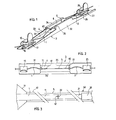
- the groove comprises (FIG. 2) a central part designated by 5, framed by two lateral parts of larger cross section denoted 61 and 62, these ending at their free ends by flared mouths 71 and 72.
- the central groove 5 and the lateral grooves 61 and 62 can each be considered as cylindrical or prismatic surfaces resting on a determined cross section, weaker for part 5 than for parts 61 and 62.
- the mouths 71 and 72 are frustoconical surfaces or pyramidal ones which rest, in general, on the same form of cross section.
- a rigid surfaced plate denoted 8 is held in abutment on the surface 40 of the support 4.
- the rigid surfaced plate 8 is preferably maintained by claws 34 and 35, integral with the lateral parts 32 and 33 of the base 31, the assembly thus forming a belt around the part made of soft material 4 and the upper plate 8.
- each of the steps of fixing the two fibers to be connected relative to the support is carried out so as to ensure a low buckling of the two fibers, buckling which produces the stress of the two fibers towards one another. other, and by the permanent axial thrust thus exerted, maintains over time the close contact between the two end faces of the fibers in the groove.
- This buckling can be achieved either by placing the fixing blocks 15 and 25 slightly offset axially relative to the axis of the groove 5, or by leaving these two blocks in the axis of the groove, but by bringing them closer to the support 4 taking into account the free length of the fibers so that ensure the buckling of these.
- the groove 5 is previously filled with an adapter liquid of index 59 (FIG. 10), which improves the light transmission from one fiber to the other, in a manner known per se.
- this index adapter liquid also performs a self-cleaning of the area between the two front faces of the fibers, namely 12 and 22, taking into account the piston effect produced by these in the groove 5 during their relative movement of introduction along the respective axes 19 and 29, the liquid being expelled in particular from the bottom side 53 of the groove 5 and the passages 54 and 55 (FIG. 11 ).
- the fibers are prepared by removing their sheath over a certain length, and obtaining front faces with properties capable of ensuring good interconnection.
- the stripped portions of fibers 1 and 2 have been noted 11 and 21, respectively. These parts 11 and 21 come into the groove 5 proper.
- a device for connecting optical fibers comprising a. support 4 of which at least one surface 40, made of soft material, elastically deformable, comprises a straight groove 5, suitable for receiving face to face the respective ends 11 and 12 of two optical fibers 1 and 2 to be connected, ends each of which has a flat front face, respectively 12 and 22, perpendicular to the axis of the fiber, and with a surface of the mirror-gloss type.
- the member which keeps the fibers in abutment on the surface of the support is a rigid surfaced plate 8, which exerts the above-mentioned pressure action, with the advantages which result therefrom.
- each of the other grooves in question terminates pref - rence at its free end with a widened mouth.
- Figure 2 shows the two flared mouths 71 and 72 ending the lateral grooves 61 and 62, and.
- Figures 3 and 12 show the mouth 71 on an enlarged scale.
- the soft material part 4 of the support is produced in the form of a single block.
- the groove itself, in its central part 5, can take various forms.
- Figure 4 shows a first shape, where the groove 5 has a general shape of V in cross section, with two sides 51 and 52, and a vertex 53, the two sides 51 and 52 being arranged symmetrically with respect to an axis 54 perpendicular to the surface 40 of the block.
- the groove 61 ends with a generally conical mouth 71, in turn defined by two sides 74 and 75 which are always symmetrical with respect to a perpendicular to the surface 40.
- the mouth 71 terminates on the lateral face 41 of the support 4.
- FIG. 13 shows an alternative embodiment of the present invention, in which the part made of soft material of the support is made in several pieces.
- the support comprises a rigid lower plate 103, on which are fixed, for example by gluing, a plurality of profiles of soft material denoted 104, rigidly held side by side, so as to define between them at least one groove 5
- the glass plate 108 On the face of the profiles which is opposite to the plate 103 is arranged the glass plate 108 already mentioned, and the plates 108 and 103 are held relative to each other by means of claws 133 and 134.
- the groove 5 is in the general shape of V with curvilinear sides, these having convex branches seen from the inside of the V. Many of the shapes of grooves already mentioned can be produced from the same way.
- the piece of soft material 4 has a groove of generally square or rectangular cross section, defined by two vertical sides 151 and 153 joined by a bottom 152.
- groove 5 has a challenge cross section denies by four segments, successively noted 251, 252, 254 and 255.
- the bottom of the groove is noted 253.
- Figure 9 While the structure of Figure 6 remains symmetrical with respect to a perpendicular to the surface 40, there is illustrated in Figure 9 an asymmetric structure.
- the groove has a cross section defined by an oblique side 551, and one side at the vertical limit 552, the bottom of the groove being noted 550.
- the vertical side 552 coincides with the perpendicular 54 to the upper surface 40 of the piece of soft material 4.
- the groove has a cross section defined by one or more curvilinear segments, which can be combined with one or more straight segments.
- the groove 5 is in the form of a gutter, it therefore consists of a single curvilinear segment 350, which ends at 351 and 352 on the upper face 40 of the block 4.
- the groove 5 is defined by a curvilinear V-shaped cross section with convex branches 451 and 452, seen from the interior of the V.
- the device of the previously known documents used two pieces of soft material placed on either side of the end of the fiber while trusting the elasticity of the two pieces to achieve a suitable coaxiality of the two fibers, and therefore their alignment.
- the device of the present invention using a single part made of soft material, and a rigid plate disposed on the other side of the fiber, nevertheless allow an alignment of the two fibers to be connected d '' sufficient to achieve a good optical interconnection of the two fibers.
- Initial experiments carried out by the Applicant have shown that the attenuation values obtained at the interconnection between the two fibers are of the order of one tenth of a decibel, which constitutes an excellent optical connection.
- the device and the method of the present invention work well, even if the fibers to be connected have slightly different diameters due to the manufacturing tolerances (provenance, or different lots).
- the means of the present invention are also remarkable for their simplicity. Finally, they adapt very well to the fragility and the very small size of the fibers.
- the upper plate 8 is, as previously indicated, a glass plate of sufficient thickness to ensure its rigidity. It is currently considered that a thickness of the order of a millimeter is sufficient.
- the block of soft material, or the profiles of soft material, according to the embodiment are molded or machined in an elastomer of the silicone elastomer type, such as the silastene sold by the company RHONE-POULENC.
- the base of the support is for example metallic.
- the index adapter medium is preferably a silicone oil such as DOW CORNING liquid no. SI 200 (fluidity 50 cp).
- the part made of soft material now noted 104, has several grooves 105.
- the grooves 105 have been illustrated in FIG. 14 as simple straight grooves. Preferably, in practice, these are central grooves extended by larger lateral grooves and end mouths, as illustrated for example in FIG. 12.
- the base 103 is provided with lugs 138 and 139 which allow its fixation. Laterally, this base 103 is completed with uprights 132 and 133 which join in the upper part the claws 134 and 135 ensuring the fixing and the maintenance of the glass plate 108, and the belt of this plate 108 with the block of soft material 104 , as previously indicated.
- the lateral faces of the block of soft material are denoted 141 and 142.
- FIG. 14 a single connection between fibers is illustrated, the fibers being denoted 101 and 102, and coming to be placed end to end inside one grooves 105.
- each fiber is housed in an elastomeric sleeve (not visible) which passes through a channel 118 where it is held by a screw 119.
- Channel and screws are preferably made of synthetic material. This avoids breaking and micro-bending of the optical fibers, which would adversely affect their quality of light transmission. We also recognize the buckling performed on the two optical fibers 101 and 102.
- FIG. 15 schematically illustrates a protective box 100 enclosing a device of the type illustrated in FIG. 14.
- This box 100 has passages allowing the arrival in sealed manner of the optical fiber cables to be connected to the inside the housing.
- the box of Figure 15 is illustrated in a slightly different embodiment, where on one side ten single-fiber cables denoted respectively 101A to 101J, while a multi-fiber, ten-fiber cable, denoted 102, leaves the other side.
- the fixing lugs 116, 138, 139 and 126 of FIG. 14 are naturally fixed on the body of the housing 100 of FIG. 15.
- the two fibers to be connected are suitably prepared, by obtaining front faces to be connected planar, perpendicular at their axes, and on a surface of the mirror-gloss type, and preferably by removing their protective sheaths over a sufficient length.
- the rigid part 208 is a cylindrical glass tube, the cross section of which is a circular crown. Inside is fitted the support made of soft material 204, of generally cylindrical shape, provided at the periphery with seven regularly distributed grooves. The external contour of this part 204 defines the groove-carrying surface 240. Only one of these grooves is illustrated in detail. As previously indicated, it will also be noted that the device may have only one groove.
- FIG. 17 illustrates the reciprocal arrangement, in which the rigid part is inside, forming a cylinder 308.
- the support made of soft material 304 the cross section of which is in the form of a circular crown. It internally carries seven grooves of which only one is shown (a single groove, moreover, could be used).
- the groove-carrying surface is denoted 340.
- Figures 18 and 19 illustrate another embodiment, in which the cross sections are closed and polygonal, but not regular. Those skilled in the art will understand that it is also possible to use substantially polygonal straight sections, where, for example, the angles are rounded.
- the rigid part, denoted 408 is outside.
- the support made of soft material 404 is inside, and has three grooves on its upper face.
- the closed surface which carries the grooves in it support 404 is: noted as a whole, 440.
- three fibers 1A, 1B, 1C arrive. From the other come three corresponding fibers 2A, 2B, 2C.
- their ends 11A and 21A meet substantially in the middle of the central groove 5.
- FIG. 19 illustrates a reciprocal arrangement from that of FIG. 18, in which the rigid part 508 is inside, its cross section being a right rectangle.
- the support made of soft material 504 is then outside; its internal surface carries, on its high side, three grooves as previously.
- This groove-carrying surface is designated in its example by 540 (it has in cross section the four internal sides of the support 504).
- the surfaced part of the rigid plate and the surface of holder groove are two homothetic surfaces quasi - complementary and overlapping slightly break.
- the external dimensions of the internal part - soft support or rigid part - are greater than the internal dimensions of the external part - rigid part or soft support, respectively -.
- the groove-carrying surface and the surfaced part of the rigid part may be two homologous and / or tangent surfaces, capable of exerting one on the other said relative bearing force by cooperation of their respective shapes.
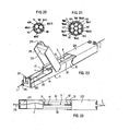
- FIGS. 20 and 21 Such an arrangement is illustrated in FIGS. 20 and 21, where the device appears in cross section.
- the rigid part In both cases, the rigid part is outside; it is denoted 608 in FIG. 20 and 708 in FIG. 21, and pre in both cases feels the shape of a circular crown in cross section.
- the soft material support is here made of several pieces. In FIG. 20, these are three profiles made of soft material, of straight cross-section, for example circular and of the same diameter (at the level of part 5 of the groove).
- the external contour defined by all of these three profiles 604A to 604C defines the groove-carrying surface 640.
- grooves are then defined between these three profiles and the inner surface of the tube 698. In each of these grooves are housed at three fiber ends, respectively denoted 11A to 11C.
- FIG. 21 illustrates a similar arrangement, but in which the support made of soft material comprises six profiles of the same diameter, regularly distributed around a seventh central profile.
- the six profiles are noted 704A to 704F, and the central profile 704G.
- the outer periphery of the profiles defines the groove-carrying surface 740, and in the grooves are housed the fiber ends 11A to 11F.
- the rigid part is preferably made of glass, or of another transparent rigid material.
- the support made of soft material, or the profiles made of soft material, are molded or machined in an elastomer of the silicone elastomer type, such as silastene sold by the company RHONE-POULENC.
- the rigid part When it is inside, the rigid part can also be made of glass, or even of any other rigid material, metallic or not.
- the groove support of soft material which is on the outside can then be either one of the elastomers already mentioned, or another synthetic material of comparable mechanical properties, and which is transparent on at least part of the visible spectrum, to facilitate control of the connection of optical fibers.
- FIGS. 22 and 23 show an improved variant of the invention, and are compared with FIGS. 1 and 2.
- the improvement essentially relates to the means for fixing the two optical fibers to be connected, on either side of the groove.
- the base 3'1 of the support 3 is provided each time with two tongues folded upwards 201 and 202, the upper part of which is shaped by means of clipping.
- a block of soft material 217 such as an elastomer is placed in axial support, in principle more adherent to the fiber than that of which the groove 5 is made.
- the end of the optical fiber 1 is threaded into a souplisseau 210, then the stripped part of the optical fiber is inserted into the groove, until practically coming into contact with the other optical fiber (assumed to have already been introduced and immobilized by the other fixing 225). It is not necessarily necessary to ensure intimate contact between the ends of the two optical fibers.
- the souplisseau 210 is placed so that it only substantially accommodates half of the part of the optical fiber 1 which rests on the elastomer block 117.
- a door 215 is pivotally fixed on the support 3. Internally, the door 215 houses an elastomer block 218 homologous with the block 217. The top of the door 215 is provided with a tongue 219 which is inserted between the two tabs 201 and 202, which can then come into engagement on the door and immobilize it by clipping.
- optical fiber 1 no longer necessarily has to undergo a slight buckling between its fixing by the blocks 217 and 218 and its guidance by the grooved block 4.
- the index adapter medium can be omitted in certain applications.
Landscapes
- Physics & Mathematics (AREA)
- General Physics & Mathematics (AREA)
- Optics & Photonics (AREA)
- Mechanical Coupling Of Light Guides (AREA)
Priority Applications (1)
| Application Number | Priority Date | Filing Date | Title |
|---|---|---|---|
| AT84400448T ATE53676T1 (de) | 1983-03-11 | 1984-03-06 | Verfahren und vorrichtung zum verbinden optischer fasern. |
Applications Claiming Priority (4)
| Application Number | Priority Date | Filing Date | Title |
|---|---|---|---|
| FR8304082 | 1983-03-11 | ||
| FR8304082A FR2542458B1 (fr) | 1983-03-11 | 1983-03-11 | Procede et dispositif de raccordement de fibres optiques |
| FR8306499 | 1983-04-20 | ||
| FR8306499A FR2544876B2 (fr) | 1983-04-20 | 1983-04-20 | Dispositifs perfectionnes pour le raccordement de fibres optiques |
Publications (3)
| Publication Number | Publication Date |
|---|---|
| EP0122169A2 true EP0122169A2 (de) | 1984-10-17 |
| EP0122169A3 EP0122169A3 (en) | 1987-08-19 |
| EP0122169B1 EP0122169B1 (de) | 1990-06-13 |
Family
ID=26223330
Family Applications (1)
| Application Number | Title | Priority Date | Filing Date |
|---|---|---|---|
| EP84400448A Expired - Lifetime EP0122169B1 (de) | 1983-03-11 | 1984-03-06 | Verfahren und Vorrichtung zum Verbinden optischer Fasern |
Country Status (5)
| Country | Link |
|---|---|
| US (1) | US4629284A (de) |
| EP (1) | EP0122169B1 (de) |
| CA (1) | CA1241824A (de) |
| DE (1) | DE3482500D1 (de) |
| ES (1) | ES8500662A1 (de) |
Cited By (14)
| Publication number | Priority date | Publication date | Assignee | Title |
|---|---|---|---|---|
| GB2179177A (en) * | 1985-08-19 | 1987-02-25 | Telephone Cables Ltd | Grooved connectors for optical fibres |
| FR2589250A1 (fr) * | 1985-10-29 | 1987-04-30 | Telecommunications Sa | Dispositif de raccordement de fibres optiques |
| EP0244225A3 (en) * | 1986-05-01 | 1989-06-07 | Minnesota Mining And Manufacturing Company | Optic fiber connector |
| US4861133A (en) * | 1987-03-27 | 1989-08-29 | Ant Nachrichtentechnik Gmbh | Device for applying a splice protector to optical conductors |
| US4968109A (en) * | 1984-04-19 | 1990-11-06 | E. I. Du Pont De Nemours And Company | Press bonding apparatus method for terminating an optical fiber with a plastically deformable termination member |
| EP0479415A3 (en) * | 1990-09-06 | 1992-07-01 | Reliance Comm/Tec Corporation | Fiber optic splicer |
| US5216741A (en) * | 1991-03-08 | 1993-06-01 | Koninklijke Ptt Nederland N.V. | Method of positioning and fixing optical fibres in a row of optical fibres and a coupling device provided with such a row of fibres |
| EP0553606A1 (de) * | 1992-01-13 | 1993-08-04 | Telia Ab | Methode und Anordnung zum Spleissen von optischen Wellenleitern |
| FR2698451A1 (fr) * | 1992-11-25 | 1994-05-27 | Mars Actel | Mandrin de retenue d'au moins une fibre optique. |
| EP0810455A1 (de) * | 1996-05-30 | 1997-12-03 | Fujikura Ltd. | Faseroptischer mechanischer Spleiss |
| EP0838705A1 (de) * | 1996-10-24 | 1998-04-29 | Alcatel | Faseroptisches Bundel mit geordneter Struktur |
| US5812718A (en) * | 1996-03-27 | 1998-09-22 | Minnesota Mining And Manufacturing Company | Method for connecting optical fibers and the interconnection |
| WO2007017948A1 (ja) * | 2005-08-11 | 2007-02-15 | Honda Tsushin Kogyo Co., Ltd. | フレキシブル光導波路用コネクタ |
| EP2357138A1 (de) | 2010-02-12 | 2011-08-17 | Tetra Laval Holdings & Finance S.A. | Vorrichtung und Verfahren zum Zuführen einer Bahn eines Verpackungsmaterials |
Families Citing this family (53)
| Publication number | Priority date | Publication date | Assignee | Title |
|---|---|---|---|---|
| FR2558966B1 (fr) * | 1984-01-31 | 1986-07-04 | Alliance Tech Ind | Coupleur-repartiteur a fibres optiques et son procede de fabrication |
| US4735477A (en) * | 1984-12-11 | 1988-04-05 | Amp Incorporated | Fiber optic splice terminal and method of using same |
| GB8510263D0 (en) * | 1985-04-23 | 1985-05-30 | British Telecomm | Optical fibre arrays |
| NL8503409A (nl) * | 1985-12-11 | 1987-07-01 | Philips Nv | Inrichting voor het verbinden van lichtgeleidende vezels. |
| US4728171A (en) * | 1986-10-20 | 1988-03-01 | Amphenol Corporation | System for use in temporary repair of multiple fiber cable |
| US4804241A (en) * | 1986-12-08 | 1989-02-14 | Chevron Research Company | Optical fiber holder |
| US4839635A (en) * | 1987-01-12 | 1989-06-13 | Inwave Corporation | Signboard for displaying optical images |
| DE3711940A1 (de) * | 1987-04-09 | 1988-10-20 | Standard Elektrik Lorenz Ag | Vielfach-steckverbinder fuer lichtwellenleiter |
| JPS63165603U (de) * | 1987-04-20 | 1988-10-28 | ||
| US4789217A (en) * | 1987-05-05 | 1988-12-06 | Tektronix, Inc. | Method of and apparatus for securing elongate members of generally cylindrical form in end-to-end relationship |
| US4784456A (en) * | 1987-05-06 | 1988-11-15 | E. I. Du Pont De Nemours And Company | Fiber optic connector |
| DE3802240A1 (de) * | 1987-09-30 | 1989-04-20 | Krone Ag | Verbindungselement fuer lichtwellenleiter |
| US4854661A (en) * | 1987-11-05 | 1989-08-08 | Gte Products Corporation | Splice cradle |
| US5159653A (en) * | 1988-04-18 | 1992-10-27 | Minnesota Mining And Manufacturing Company | Optical fiber splice |
| JP2533014Y2 (ja) * | 1989-02-10 | 1997-04-16 | 日本電気硝子 株式会社 | リボン状多心光ファイバの永久接続器 |
| US4883336A (en) * | 1989-02-17 | 1989-11-28 | Conseil National De Recherches Du Canada | Method and leadthrough system for laying out optical fibres across an aperture of a container shell |
| US5377289A (en) * | 1989-08-02 | 1994-12-27 | E. I. Du Pont De Nemours And Company | Optical fiber connector having an apparatus for positioning the center of an optical fiber along a predetermined reference axis |
| US5243673A (en) * | 1989-08-02 | 1993-09-07 | E. I. Du Pont De Nemours And Company | Opto-electronic component having positioned optical fiber associated therewith |
| US5404417A (en) * | 1989-08-02 | 1995-04-04 | E. I. Du Pont De Nemours And Company | Apparatus for positioning the center of an optical fiber along a predetermined reference axis |
| US4997255A (en) * | 1989-12-07 | 1991-03-05 | Northern Telecom Limited | Optical fiber splice retainer and method for its use |
| US5133033A (en) * | 1990-05-31 | 1992-07-21 | Northern Telecom Limited | Optical fiber mechanical splice and method for its use |
| USD334734S (en) | 1990-09-06 | 1993-04-13 | Reliance Comm/Tec Corporation | Optical fiber splicer |
| DE4041030A1 (de) * | 1990-12-20 | 1992-07-02 | Siemens Ag | Krimpspleiss |
| AU649162B2 (en) * | 1991-08-17 | 1994-05-12 | Nippon Telegraph & Telephone Corporation | Optical connector |
| CA2116667A1 (en) * | 1991-08-30 | 1993-03-18 | Melvin Harry Johnson | An optical fiber connector having an apparatus for positioning the center of an optical fiber along a predetermined reference axis |
| US5155781A (en) * | 1991-09-06 | 1992-10-13 | Minnesota Mining And Manufacturing Company | Multiple optical fiber splice with sealing end covers |
| SE500945C2 (sv) * | 1992-05-19 | 1994-10-03 | Stiftelsen Inst Foer Mikroelek | Skarvdon för ljusfibrer |
| FR2694417B1 (fr) * | 1992-07-31 | 1994-09-16 | Alcatel Cable | Ruban de fibres optiques individualisées. |
| US5375181A (en) * | 1992-08-12 | 1994-12-20 | Micron Optics, Inc. | Temperature compensated fiber fabry-perot filters |
| US5509093A (en) * | 1993-10-13 | 1996-04-16 | Micron Optics, Inc. | Temperature compensated fiber fabry-perot filters |
| JP2001074982A (ja) * | 1999-09-08 | 2001-03-23 | Nec Corp | 光モジュールの光結合装置及びその光結合方法 |
| FR2817628B1 (fr) * | 2000-12-05 | 2003-01-03 | Commissariat Energie Atomique | Structure de separation et de prepositionnement d'un ensemble de fibres et dispositif destine a recevoir un ensemble de fibres |
| US6985666B2 (en) * | 2001-02-28 | 2006-01-10 | Asahi Glass Company, Limited | Method for coupling plastic optical fibers |
| DE50102122D1 (de) * | 2001-11-10 | 2004-06-03 | Agilent Technologies Inc | Kabelhalter |
| US20030185520A1 (en) * | 2002-03-26 | 2003-10-02 | Bookbinder Dana C. | Device and method for coupling optical fibers |
| WO2004036700A2 (en) * | 2002-10-15 | 2004-04-29 | Micron Optics, Inc. | Waferless fiber fabry-perot filters |
| EP1583989A4 (de) * | 2002-12-20 | 2006-07-05 | Micron Optics Inc | Temperatur kompensierter ferrulen halter für einen fabry-perot-faserfilter |
| WO2005121726A2 (en) * | 2004-01-07 | 2005-12-22 | The United States Of America, As Represented By The Secretary Of The Navy | Method and apparatus for identifying a substance |
| US20060067636A1 (en) * | 2004-09-24 | 2006-03-30 | 3M Innovative Properties Company | Connector and splice holder device |
| US7333709B2 (en) * | 2004-09-24 | 2008-02-19 | 3M Innovative Properties Company | Splice holder device |
| JP4821209B2 (ja) * | 2005-04-14 | 2011-11-24 | 住友電気工業株式会社 | 光コネクタ及び光コネクタの組立方法 |
| JP3121157U (ja) * | 2006-02-13 | 2006-04-27 | 糸子 樋口 | メカニカルスプライス |
| US7534051B2 (en) * | 2006-04-12 | 2009-05-19 | Sumitomo Electric Industries, Ltd. | Optical fiber connector, optical fiber connecting method, and connector converter |
| JP4915243B2 (ja) * | 2007-01-15 | 2012-04-11 | 日立電線株式会社 | 光コネクタ |
| WO2009111176A1 (en) * | 2008-02-29 | 2009-09-11 | 3M Innovative Properties Company | Connecting structure for optical cable |
| US8485735B2 (en) * | 2008-12-19 | 2013-07-16 | US Conec, Ltd | Field install fiber clip and method of use |
| US8295669B2 (en) * | 2009-08-27 | 2012-10-23 | 3M Innovative Properties Company | Compact optical fiber splice holder device |
| JP6383617B2 (ja) * | 2014-09-11 | 2018-08-29 | 株式会社フジクラ | 光ファイバ接続構造、光ファイバ接続器 |
| US10656362B2 (en) | 2018-01-04 | 2020-05-19 | Globalfoundries Singapore Pte. Ltd. | Gamma groove arrays for interconnecting and mounting devices |
| CN112363274B (zh) * | 2020-11-04 | 2025-07-11 | 莱特尔科技(深圳)有限公司 | 一种光纤合束器制作装置和光纤合束器制作方法 |
| CN115291337B (zh) * | 2022-07-25 | 2024-10-22 | 无锡芯光互连技术研究院有限公司 | 一种mt接口光纤连接和固定装置 |
| GB2619784B (en) * | 2022-11-04 | 2024-06-05 | Alker Fibre Optic Specialists Ltd | Fibre optic cable splicing apparatus and method |
| WO2024095019A1 (en) * | 2022-11-04 | 2024-05-10 | Alker Fibre Optic Specialists Limited | Brace, rig and method for mechanically splicing a fibre optic cable |
Family Cites Families (20)
| Publication number | Priority date | Publication date | Assignee | Title |
|---|---|---|---|---|
| GB1430979A (en) * | 1973-12-13 | 1976-04-07 | Post Office | Dielectric optical waveguides |
| CA1053491A (en) * | 1974-08-19 | 1979-05-01 | Robert M. Hawk | Optical waveguide connector |
| DE2456552C2 (de) * | 1974-11-29 | 1983-12-01 | Siemens AG, 1000 Berlin und 8000 München | Verbindung von zwei Glasfaserbündeln und Verfahren zur Herstellung der Verbindung |
| DE2518319C2 (de) * | 1975-04-24 | 1981-11-05 | Siemens AG, 1000 Berlin und 8000 München | Loesbare Spleissverbindung fuer Lichtwellenleiterkabel |
| DE2522740C3 (de) * | 1975-05-22 | 1981-05-14 | Siemens AG, 1000 Berlin und 8000 München | Vorrichtung zum Verbinden eines ankommenden Lichtleitfaserkabels mit einem weiterführenden und Verfahren zur Herstellung der Vorrichtung |
| US4102561A (en) * | 1975-07-02 | 1978-07-25 | Corning Glass Works | Optical waveguide connector |
| DE2611658C3 (de) * | 1976-03-19 | 1981-12-17 | Licentia Patent-Verwaltungs-Gmbh, 6000 Frankfurt | Justiervorrichtung für Lichtleitfasern |
| US4172746A (en) * | 1976-03-31 | 1979-10-30 | Noane Georges Le | Method for on-site connection of cables with optical fibres |
| US4046454A (en) * | 1976-05-18 | 1977-09-06 | Bell Telephone Laboratories, Incorporated | Optical fiber connector |
| JPS5310445A (en) * | 1976-07-15 | 1978-01-30 | Furukawa Electric Co Ltd:The | Aligned joint of optical fibers |
| FR2360896A1 (fr) * | 1976-08-03 | 1978-03-03 | Lignes Telegraph Telephon | Structure de raccordement pour cable a fibres optiques |
| US4186997A (en) * | 1977-02-14 | 1980-02-05 | Amp Incorporated | Overlap type waveguide connector assembly and method |
| JPS5434251A (en) * | 1977-08-22 | 1979-03-13 | Nippon Telegr & Teleph Corp <Ntt> | Multiconnector for optical fibers |
| JPS54106246A (en) * | 1978-02-07 | 1979-08-21 | Nippon Telegr & Teleph Corp <Ntt> | Connectors for optical fibers |
| US4184741A (en) * | 1978-02-27 | 1980-01-22 | Corning Glass Works | Filament-to-device coupler |
| FR2443075A1 (fr) * | 1978-08-29 | 1980-06-27 | Comp Generale Electricite | Fiche de connecteur fibre a fibre avec element de raccordement a un cable optique |
| GB2046466B (en) * | 1979-01-24 | 1983-02-16 | Bicc Ltd | Joining optical fibres using magnifier |
| US4257674A (en) * | 1979-04-23 | 1981-03-24 | Gte Products Corporation | Elastomeric fiber optic splice |
| US4302267A (en) * | 1980-02-20 | 1981-11-24 | General Dynamics, Pomona Division | Optical fiber mating apparatus and method |
| JPS584110A (ja) * | 1981-06-30 | 1983-01-11 | Kyocera Corp | 光フアイバ用マルチコネクタ |
-
1984
- 1984-03-06 EP EP84400448A patent/EP0122169B1/de not_active Expired - Lifetime
- 1984-03-06 US US06/586,748 patent/US4629284A/en not_active Expired - Fee Related
- 1984-03-06 DE DE8484400448T patent/DE3482500D1/de not_active Expired - Fee Related
- 1984-03-08 ES ES530378A patent/ES8500662A1/es not_active Expired
- 1984-03-12 CA CA000449347A patent/CA1241824A/en not_active Expired
Cited By (23)
| Publication number | Priority date | Publication date | Assignee | Title |
|---|---|---|---|---|
| US4968109A (en) * | 1984-04-19 | 1990-11-06 | E. I. Du Pont De Nemours And Company | Press bonding apparatus method for terminating an optical fiber with a plastically deformable termination member |
| GB2179177A (en) * | 1985-08-19 | 1987-02-25 | Telephone Cables Ltd | Grooved connectors for optical fibres |
| FR2589250A1 (fr) * | 1985-10-29 | 1987-04-30 | Telecommunications Sa | Dispositif de raccordement de fibres optiques |
| EP0226482A1 (de) * | 1985-10-29 | 1987-06-24 | Societe Anonyme De Telecommunications (S.A.T.) | Verbindung für optische Fasern |
| EP0244225A3 (en) * | 1986-05-01 | 1989-06-07 | Minnesota Mining And Manufacturing Company | Optic fiber connector |
| US4861133A (en) * | 1987-03-27 | 1989-08-29 | Ant Nachrichtentechnik Gmbh | Device for applying a splice protector to optical conductors |
| EP0283658A3 (de) * | 1987-03-27 | 1990-08-08 | ANT Nachrichtentechnik GmbH | Vorrichtung zum Anbringen eines Spleissschutzes an Lichtwellenleitern |
| EP0479415A3 (en) * | 1990-09-06 | 1992-07-01 | Reliance Comm/Tec Corporation | Fiber optic splicer |
| US5216741A (en) * | 1991-03-08 | 1993-06-01 | Koninklijke Ptt Nederland N.V. | Method of positioning and fixing optical fibres in a row of optical fibres and a coupling device provided with such a row of fibres |
| EP0553606A1 (de) * | 1992-01-13 | 1993-08-04 | Telia Ab | Methode und Anordnung zum Spleissen von optischen Wellenleitern |
| FR2698451A1 (fr) * | 1992-11-25 | 1994-05-27 | Mars Actel | Mandrin de retenue d'au moins une fibre optique. |
| EP0599723A1 (de) * | 1992-11-25 | 1994-06-01 | Alcatel Cable Interface | Klemme zum Halten von mindestens einer optischen Faser |
| US5416883A (en) * | 1992-11-25 | 1995-05-16 | Mars Actel | Clamp for retaining at least one optical fiber |
| US5812718A (en) * | 1996-03-27 | 1998-09-22 | Minnesota Mining And Manufacturing Company | Method for connecting optical fibers and the interconnection |
| WO1997036200A3 (en) * | 1996-03-27 | 2000-02-17 | Minnesota Mining & Mfg | Method for connecting optical fibers and the interconnection |
| EP0810455A1 (de) * | 1996-05-30 | 1997-12-03 | Fujikura Ltd. | Faseroptischer mechanischer Spleiss |
| US5963699A (en) * | 1996-05-30 | 1999-10-05 | Fujikura Ltd. | Optical fiber mechanical splice |
| EP0838705A1 (de) * | 1996-10-24 | 1998-04-29 | Alcatel | Faseroptisches Bundel mit geordneter Struktur |
| FR2755248A1 (fr) * | 1996-10-24 | 1998-04-30 | Alsthom Cge Alcatel | Faisceau de fibres optiques a structure ordonnee |
| US6125224A (en) * | 1996-10-24 | 2000-09-26 | Alcatel | Ordered structure optical fiber ribbon bundle |
| WO2007017948A1 (ja) * | 2005-08-11 | 2007-02-15 | Honda Tsushin Kogyo Co., Ltd. | フレキシブル光導波路用コネクタ |
| EP2357138A1 (de) | 2010-02-12 | 2011-08-17 | Tetra Laval Holdings & Finance S.A. | Vorrichtung und Verfahren zum Zuführen einer Bahn eines Verpackungsmaterials |
| WO2011098591A1 (en) | 2010-02-12 | 2011-08-18 | Tetra Laval Holdings & Finance S.A. | Device and method for feeding a web of a packaging material |
Also Published As
| Publication number | Publication date |
|---|---|
| US4629284A (en) | 1986-12-16 |
| ES530378A0 (es) | 1984-11-01 |
| EP0122169A3 (en) | 1987-08-19 |
| ES8500662A1 (es) | 1984-11-01 |
| CA1241824A (en) | 1988-09-13 |
| DE3482500D1 (de) | 1990-07-19 |
| EP0122169B1 (de) | 1990-06-13 |
Similar Documents
| Publication | Publication Date | Title |
|---|---|---|
| EP0122169B1 (de) | Verfahren und Vorrichtung zum Verbinden optischer Fasern | |
| EP0136201B1 (de) | Verfahren zur Verbindung von optischen Fasern und optischer Spliess auf diese Weise erhalten | |
| CA1097111A (fr) | Fiche de connecteur fibre a fibre pour cable optique multifibre | |
| CA1131952A (fr) | Connecteur pour liaison a fibre optique | |
| CA1105749A (fr) | Dispositif de raccordement global en bout de deux groupes de sept fibres optiques | |
| EP0008980B1 (de) | Faser-an-Faser-Verbindungsstecker mit einem Anschlusselement für ein optisches Kabel | |
| FR2699689A1 (fr) | Connecteur de fibres optiques. | |
| EP0051510B1 (de) | Einrichtung für die optische Fasereinstellung in einer aus einem Stück gebildeten Zwinge zum Verbinden von zwei Transmissionskabeln mittels optischer Fasern | |
| FR2538919A1 (fr) | Dispositif de raccordement rapide des extremites de fibres optiques | |
| EP0011011A1 (de) | Endhülle eines Verbindungsstücks für eine optische Einzelfaser und mit derartiger Endhülle versehenes Verbindungsstück | |
| FR2553199A1 (fr) | Connecteur de fibres optiques | |
| EP2947485B1 (de) | Optische verbindungseinheit mit verbesserter führung der optischen kontaktenden, entsprechende stecker und verbindungsverfahren | |
| FR2717912A1 (fr) | Elément de raccordement à une fibre multicÓoeur et procédé de réalisation. | |
| FR2523318A1 (fr) | Connecteur pour guides d'ondes lumineuses | |
| FR2698180A1 (fr) | Porte-épissure de fibres optiques pour cordons de fibres optiques en forme de rubans. | |
| EP0014610A1 (de) | Lösbare Verbindungsvorrichtung für optische Fasern | |
| FR2542458A1 (fr) | Procede et dispositif de raccordement de fibres optiques | |
| FR2530829A1 (fr) | Connecteur de fibres optiques | |
| EP0146471B1 (de) | Verfahren und Vorrichtung zur halbpermanenten Verbindung von optischen Fasern | |
| CA1193125A (fr) | Connecteur optique monofibre | |
| FR2535069A1 (fr) | Embout de connexion optique multi-fibres, connecteur utilisant un tel embout et appareil pour le montage de fibres dans ledit embout | |
| EP0190962B1 (de) | Vorrichtung für faseroptische Kupplung und Verfahren zu deren Herstellung | |
| FR2739458A1 (fr) | Connecteur optique et son procede de realisation | |
| FR2818839A1 (fr) | Ensemble de connexion multivoie pour fibres optiques | |
| FR2697350A1 (fr) | Porte-épissure de fibres optiques. |
Legal Events
| Date | Code | Title | Description |
|---|---|---|---|
| PUAI | Public reference made under article 153(3) epc to a published international application that has entered the european phase |
Free format text: ORIGINAL CODE: 0009012 |
|
| AK | Designated contracting states |
Designated state(s): AT BE CH DE FR GB IT LI LU NL SE |
|
| PUAL | Search report despatched |
Free format text: ORIGINAL CODE: 0009013 |
|
| AK | Designated contracting states |
Kind code of ref document: A3 Designated state(s): AT BE CH DE FR GB IT LI LU NL SE |
|
| 17P | Request for examination filed |
Effective date: 19880125 |
|
| 17Q | First examination report despatched |
Effective date: 19891019 |
|
| ITF | It: translation for a ep patent filed | ||
| GRAA | (expected) grant |
Free format text: ORIGINAL CODE: 0009210 |
|
| AK | Designated contracting states |
Kind code of ref document: B1 Designated state(s): AT BE CH DE FR GB IT LI LU NL SE |
|
| PG25 | Lapsed in a contracting state [announced via postgrant information from national office to epo] |
Ref country code: SE Effective date: 19900613 Ref country code: AT Effective date: 19900613 |
|
| REF | Corresponds to: |
Ref document number: 53676 Country of ref document: AT Date of ref document: 19900615 Kind code of ref document: T |
|
| REF | Corresponds to: |
Ref document number: 3482500 Country of ref document: DE Date of ref document: 19900719 |
|
| GBT | Gb: translation of ep patent filed (gb section 77(6)(a)/1977) | ||
| PG25 | Lapsed in a contracting state [announced via postgrant information from national office to epo] |
Ref country code: LU Free format text: LAPSE BECAUSE OF NON-PAYMENT OF DUE FEES Effective date: 19910331 |
|
| PLBE | No opposition filed within time limit |
Free format text: ORIGINAL CODE: 0009261 |
|
| STAA | Information on the status of an ep patent application or granted ep patent |
Free format text: STATUS: NO OPPOSITION FILED WITHIN TIME LIMIT |
|
| 26N | No opposition filed | ||
| PGFP | Annual fee paid to national office [announced via postgrant information from national office to epo] |
Ref country code: GB Payment date: 19930305 Year of fee payment: 10 |
|
| PGFP | Annual fee paid to national office [announced via postgrant information from national office to epo] |
Ref country code: BE Payment date: 19930317 Year of fee payment: 10 |
|
| PGFP | Annual fee paid to national office [announced via postgrant information from national office to epo] |
Ref country code: CH Payment date: 19930325 Year of fee payment: 10 |
|
| ITTA | It: last paid annual fee | ||
| PGFP | Annual fee paid to national office [announced via postgrant information from national office to epo] |
Ref country code: NL Payment date: 19930331 Year of fee payment: 10 |
|
| PG25 | Lapsed in a contracting state [announced via postgrant information from national office to epo] |
Ref country code: GB Effective date: 19940306 |
|
| PG25 | Lapsed in a contracting state [announced via postgrant information from national office to epo] |
Ref country code: LI Effective date: 19940331 Ref country code: CH Effective date: 19940331 Ref country code: BE Effective date: 19940331 |
|
| BERE | Be: lapsed |
Owner name: ALLIANCE TECHNIQUE INDUSTRIELLE Effective date: 19940331 |
|
| PG25 | Lapsed in a contracting state [announced via postgrant information from national office to epo] |
Ref country code: NL Effective date: 19941001 |
|
| GBPC | Gb: european patent ceased through non-payment of renewal fee |
Effective date: 19940306 |
|
| NLV4 | Nl: lapsed or anulled due to non-payment of the annual fee | ||
| REG | Reference to a national code |
Ref country code: CH Ref legal event code: PL |
|
| PGFP | Annual fee paid to national office [announced via postgrant information from national office to epo] |
Ref country code: DE Payment date: 20010704 Year of fee payment: 18 |
|
| PG25 | Lapsed in a contracting state [announced via postgrant information from national office to epo] |
Ref country code: DE Free format text: LAPSE BECAUSE OF NON-PAYMENT OF DUE FEES Effective date: 20021001 |
|
| PGFP | Annual fee paid to national office [announced via postgrant information from national office to epo] |
Ref country code: FR Payment date: 20030327 Year of fee payment: 20 |