EP0122196A1 - Hydraulisches Bremsen-System - Google Patents
Hydraulisches Bremsen-System Download PDFInfo
- Publication number
- EP0122196A1 EP0122196A1 EP84400672A EP84400672A EP0122196A1 EP 0122196 A1 EP0122196 A1 EP 0122196A1 EP 84400672 A EP84400672 A EP 84400672A EP 84400672 A EP84400672 A EP 84400672A EP 0122196 A1 EP0122196 A1 EP 0122196A1
- Authority
- EP
- European Patent Office
- Prior art keywords
- bellows
- friction
- chamber
- annular
- friction element
- Prior art date
- Legal status (The legal status is an assumption and is not a legal conclusion. Google has not performed a legal analysis and makes no representation as to the accuracy of the status listed.)
- Granted
Links
- 229910052751 metal Inorganic materials 0.000 claims abstract description 10
- 239000002184 metal Substances 0.000 claims abstract description 10
- 239000007788 liquid Substances 0.000 claims abstract description 9
- 230000006835 compression Effects 0.000 claims description 6
- 238000007906 compression Methods 0.000 claims description 6
- 230000000694 effects Effects 0.000 description 6
- 230000003416 augmentation Effects 0.000 description 5
- 235000021183 entrée Nutrition 0.000 description 4
- 239000012530 fluid Substances 0.000 description 4
- 239000000463 material Substances 0.000 description 3
- 230000000750 progressive effect Effects 0.000 description 3
- 238000000429 assembly Methods 0.000 description 2
- 238000000576 coating method Methods 0.000 description 2
- 238000004519 manufacturing process Methods 0.000 description 2
- 230000002093 peripheral effect Effects 0.000 description 2
- 125000006850 spacer group Chemical group 0.000 description 2
- 229910000838 Al alloy Inorganic materials 0.000 description 1
- 229910000851 Alloy steel Inorganic materials 0.000 description 1
- 240000008042 Zea mays Species 0.000 description 1
- 230000000712 assembly Effects 0.000 description 1
- 230000015556 catabolic process Effects 0.000 description 1
- 239000011248 coating agent Substances 0.000 description 1
- 239000002131 composite material Substances 0.000 description 1
- 238000011010 flushing procedure Methods 0.000 description 1
- 230000005923 long-lasting effect Effects 0.000 description 1
- 230000007257 malfunction Effects 0.000 description 1
- 239000007769 metal material Substances 0.000 description 1
- 229910044991 metal oxide Inorganic materials 0.000 description 1
- 150000004706 metal oxides Chemical class 0.000 description 1
- 239000000203 mixture Substances 0.000 description 1
- 238000010926 purge Methods 0.000 description 1
- 238000011084 recovery Methods 0.000 description 1
- 230000002787 reinforcement Effects 0.000 description 1
- 239000010935 stainless steel Substances 0.000 description 1
- 229910001220 stainless steel Inorganic materials 0.000 description 1
- 238000011144 upstream manufacturing Methods 0.000 description 1
Images

Classifications
-
- F—MECHANICAL ENGINEERING; LIGHTING; HEATING; WEAPONS; BLASTING
- F16—ENGINEERING ELEMENTS AND UNITS; GENERAL MEASURES FOR PRODUCING AND MAINTAINING EFFECTIVE FUNCTIONING OF MACHINES OR INSTALLATIONS; THERMAL INSULATION IN GENERAL
- F16D—COUPLINGS FOR TRANSMITTING ROTATION; CLUTCHES; BRAKES
- F16D65/00—Parts or details
- F16D65/38—Slack adjusters
- F16D65/40—Slack adjusters mechanical
- F16D65/52—Slack adjusters mechanical self-acting in one direction for adjusting excessive play
- F16D65/54—Slack adjusters mechanical self-acting in one direction for adjusting excessive play by means of direct linear adjustment
-
- F—MECHANICAL ENGINEERING; LIGHTING; HEATING; WEAPONS; BLASTING
- F16—ENGINEERING ELEMENTS AND UNITS; GENERAL MEASURES FOR PRODUCING AND MAINTAINING EFFECTIVE FUNCTIONING OF MACHINES OR INSTALLATIONS; THERMAL INSULATION IN GENERAL
- F16D—COUPLINGS FOR TRANSMITTING ROTATION; CLUTCHES; BRAKES
- F16D55/00—Brakes with substantially-radial braking surfaces pressed together in axial direction, e.g. disc brakes
- F16D55/02—Brakes with substantially-radial braking surfaces pressed together in axial direction, e.g. disc brakes with axially-movable discs or pads pressed against axially-located rotating members
- F16D55/04—Brakes with substantially-radial braking surfaces pressed together in axial direction, e.g. disc brakes with axially-movable discs or pads pressed against axially-located rotating members by moving discs or pads away from one another against radial walls of drums or cylinders
- F16D55/06—Brakes with substantially-radial braking surfaces pressed together in axial direction, e.g. disc brakes with axially-movable discs or pads pressed against axially-located rotating members by moving discs or pads away from one another against radial walls of drums or cylinders without self-tightening action
- F16D55/10—Brakes actuated by a fluid-pressure device arranged in or on the brake
-
- F—MECHANICAL ENGINEERING; LIGHTING; HEATING; WEAPONS; BLASTING
- F16—ENGINEERING ELEMENTS AND UNITS; GENERAL MEASURES FOR PRODUCING AND MAINTAINING EFFECTIVE FUNCTIONING OF MACHINES OR INSTALLATIONS; THERMAL INSULATION IN GENERAL
- F16D—COUPLINGS FOR TRANSMITTING ROTATION; CLUTCHES; BRAKES
- F16D55/00—Brakes with substantially-radial braking surfaces pressed together in axial direction, e.g. disc brakes
- F16D55/02—Brakes with substantially-radial braking surfaces pressed together in axial direction, e.g. disc brakes with axially-movable discs or pads pressed against axially-located rotating members
- F16D55/22—Brakes with substantially-radial braking surfaces pressed together in axial direction, e.g. disc brakes with axially-movable discs or pads pressed against axially-located rotating members by clamping an axially-located rotating disc between movable braking members, e.g. movable brake discs or brake pads
-
- F—MECHANICAL ENGINEERING; LIGHTING; HEATING; WEAPONS; BLASTING
- F16—ENGINEERING ELEMENTS AND UNITS; GENERAL MEASURES FOR PRODUCING AND MAINTAINING EFFECTIVE FUNCTIONING OF MACHINES OR INSTALLATIONS; THERMAL INSULATION IN GENERAL
- F16D—COUPLINGS FOR TRANSMITTING ROTATION; CLUTCHES; BRAKES
- F16D65/00—Parts or details
- F16D65/14—Actuating mechanisms for brakes; Means for initiating operation at a predetermined position
- F16D65/16—Actuating mechanisms for brakes; Means for initiating operation at a predetermined position arranged in or on the brake
- F16D65/18—Actuating mechanisms for brakes; Means for initiating operation at a predetermined position arranged in or on the brake adapted for drawing members together, e.g. for disc brakes
- F16D65/186—Actuating mechanisms for brakes; Means for initiating operation at a predetermined position arranged in or on the brake adapted for drawing members together, e.g. for disc brakes with full-face force-applying member, e.g. annular
-
- F—MECHANICAL ENGINEERING; LIGHTING; HEATING; WEAPONS; BLASTING
- F16—ENGINEERING ELEMENTS AND UNITS; GENERAL MEASURES FOR PRODUCING AND MAINTAINING EFFECTIVE FUNCTIONING OF MACHINES OR INSTALLATIONS; THERMAL INSULATION IN GENERAL
- F16D—COUPLINGS FOR TRANSMITTING ROTATION; CLUTCHES; BRAKES
- F16D65/00—Parts or details
- F16D65/38—Slack adjusters
- F16D65/72—Slack adjusters hydraulic
- F16D65/74—Slack adjusters hydraulic self-acting in one direction
-
- F—MECHANICAL ENGINEERING; LIGHTING; HEATING; WEAPONS; BLASTING
- F16—ENGINEERING ELEMENTS AND UNITS; GENERAL MEASURES FOR PRODUCING AND MAINTAINING EFFECTIVE FUNCTIONING OF MACHINES OR INSTALLATIONS; THERMAL INSULATION IN GENERAL
- F16D—COUPLINGS FOR TRANSMITTING ROTATION; CLUTCHES; BRAKES
- F16D2121/00—Type of actuator operation force
- F16D2121/02—Fluid pressure
-
- F—MECHANICAL ENGINEERING; LIGHTING; HEATING; WEAPONS; BLASTING
- F16—ENGINEERING ELEMENTS AND UNITS; GENERAL MEASURES FOR PRODUCING AND MAINTAINING EFFECTIVE FUNCTIONING OF MACHINES OR INSTALLATIONS; THERMAL INSULATION IN GENERAL
- F16D—COUPLINGS FOR TRANSMITTING ROTATION; CLUTCHES; BRAKES
- F16D2125/00—Components of actuators
- F16D2125/02—Fluid-pressure mechanisms
- F16D2125/026—Pressure-to-pressure converters, e.g. hydropneumatic
-
- F—MECHANICAL ENGINEERING; LIGHTING; HEATING; WEAPONS; BLASTING
- F16—ENGINEERING ELEMENTS AND UNITS; GENERAL MEASURES FOR PRODUCING AND MAINTAINING EFFECTIVE FUNCTIONING OF MACHINES OR INSTALLATIONS; THERMAL INSULATION IN GENERAL
- F16D—COUPLINGS FOR TRANSMITTING ROTATION; CLUTCHES; BRAKES
- F16D2125/00—Components of actuators
- F16D2125/02—Fluid-pressure mechanisms
- F16D2125/10—Plural pistons interacting by fluid pressure, e.g. hydraulic force amplifiers using different sized pistons
-
- F—MECHANICAL ENGINEERING; LIGHTING; HEATING; WEAPONS; BLASTING
- F16—ENGINEERING ELEMENTS AND UNITS; GENERAL MEASURES FOR PRODUCING AND MAINTAINING EFFECTIVE FUNCTIONING OF MACHINES OR INSTALLATIONS; THERMAL INSULATION IN GENERAL
- F16D—COUPLINGS FOR TRANSMITTING ROTATION; CLUTCHES; BRAKES
- F16D2125/00—Components of actuators
- F16D2125/02—Fluid-pressure mechanisms
- F16D2125/14—Fluid-filled flexible members, e.g. enclosed air bladders
Definitions
- the present invention relates to hydraulic brake actuation systems, in particular for vehicles, and more particularly to a hydraulic brake actuation system of the type comprising at least one friction element disposed in the vicinity of a member to be braked, a device for hydraulic actuation comprising a chamber having at least one expandable part connected to the friction element and actuable by a pressurized liquid to move the friction element and bring it into friction contact with the member to be braked, the part expandable chamber being defined by a cylindrical metal bellows having a front end adjacent to the friction element, and means for connecting the actuating device to at least one source of pressurized liquid.
- the object of the present invention is to provide a hydraulic brake actuation system of the type defined above, making it possible, efficiently and reliably, to obtain such a play take-up by implementing a structure actuation device. simple, inexpensive and very low inertia, which is versatile and essentially free from the risk of malfunction.
- the bellows of the hydraulic actuation device is made of metal elastic, the means for connecting the bellows to the source of pressurized liquid comprising a non-return valve device.
- the natural tendency of an elastic bellows to retract is used to slightly and in a controlled manner separate the friction element from the member to be braked after cessation of the application of the braking pressure, the natural flushing effect of the fluid contained in the bellows resulting from the retraction of the latter being however immediately limited by the non-return valve device, so that the return spacing of the friction element vis-à-vis screw of the member to be braked is limited to a reduced value sufficient to avoid friction on this member to be braked as well as to prevent the breakdown effect and limit the dead travel during a subsequent reapplication of the brake, the expansion of the the bellows being thus controlled by the progressive wear of the lining of the friction element.
- a simple bellows purge allows it to automatically recover its initial retracted configuration, for example for the replacement of new friction elements.
- the bellows like the friction element, is annular, the member to be braked advantageously comprising at least two disc elements axially offset from one another, between which is disposed the annular bellows with interposition, respectively, of an annular friction element between each disc element and the adjacent end of the annular bellows.
- another object of the present invention is to propose, for an annular brake of the type defined last above, an annular brake actuation system in which the brake motor and the friction elements form a unitary assembly floating, guaranteeing an automatic backlash without requiring any additional mechanical means, thus allowing many structural variants for the realization of the discs.
- the friction elements are respectively secured at the axially opposite ends of the annular bellows, the non-return valve device being advantageously mounted on the support plate of one of the annular friction elements.
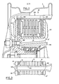
- a disc brake of the so-called annular type with spreader actuating device comprising, disposed inside a wheel hub 1, a disc structure "fork" 10 having at least two annular peripheral zones axially spaced from one another 11, 11 'defining between them an annular space in which is disposed an actuator or hydraulic spacer motor 50 intended to press against the friction surfaces facing each other screws 12, 12 'of the discs 11, 11' the friction linings 13 of annular friction elements 14 each comprising an annular support plate 15 on which is fixed the corresponding friction lining 13.
- the motor hydraulic spacer 50 is constituted by an annular bellows 51 (consisting of two concentric corrugated walls) defining an interior chamber 52 and produced made of elastic metal, for example alloy steel or stainless steel.
- the support plates 15 are directly secured, for example welded, to the axially opposite ends of the annular bellows 51, thus closing the axially opposite ends of the chamber 52.
- the support plate of the internal friction element 14 locally includes a portion 150 projecting radially outward beyond the periphery of the disc structure 10 and provided with a through opening 151 in which is mounted a non-return valve device 20 for establishing a connection between the interior chamber 52 and a source of pressurized liquid 200 (in this case a master cylinder) via a radial outward extension 152 of the interior end zone of the bellows 51 extending in line with opening 151.
- the non-return valve device 20 comprises a cylindrical body 21 formed with an internal bore 22 in which is received slidingly a piston 23 dividing the bore into an inlet chamber 24 communicating with the source pressure 200 by a connection inlet orifice 25 formed in the front end of the body 21, and a compression chamber 240 permanently connected to the internal chamber 52 of the bellows 51 via an orifice 26 in a plug 27 forming a connection mounting of the non-return device 20 on the extension 150 of the support plate of the internal friction element 14, the orifice 26 opening into the communication extension 152 of the bellows 51.
- the piston 23 has a central conical projection forming a valve 28 intended normally to bear against the seat-forming edge of the inlet orifice 25 under the effect of a spring 29 bearing on the cover and urging the piston 23 in the direction towards the orifice d 'entry 25.
- the piston 23 further comprises a central through passage 30 opening at the center of a projection 28, the opposite end, on the side of the compression chamber 25, of the passage 30 being flared to form a seat for an element ball valve 31 cooperating with a profiled cup 32 disposed in the compression chamber 240, advantageously inside the piston 23 itself, on which the other end of the spring 29 is supported, the biasing of the spring acting therefore on the piston 23 in the direction of the inlet orifice 25 by means of the ball 31 pressed against its seat and thus closing the passage 30.
- each annular support plate 15 in addition to the radial extension portion 150 of the support plate 15 of the internal friction element 14, each annular support plate 15 also has an extension 153 projecting radially outwards beyond the periphery of the disc elements 11, 11 ′ and profiled, for example in the shape of a U for cooperate in sliding with an axial longitudinal member of torque recovery 154 secured to a fixed structure 55 of the vehicle.
- the inner disc member 11 ' has a general L-shaped configuration and is secured simultaneously to the hub 1 of the wheel to the outer disc member 11 by a bolt 156.
- the design in the form of a compact unitary assembly of the hydraulic brake actuation system according to the invention further allows the production of a complete and also unitary annular braking assembly, free of leakage.
- friction linings 13 of friction linings of friction elements 14 of high resistance materials for example a mixture of sintered metallic materials and treating the friction surfaces opposite 12 and 12 'of the disc elements 11, 11 ′ so that they exhibit high characteristics of resistance to wear, for example by providing them with a coating of metal oxides, it is possible to envisage for the brake assembly a lifetime far exceeding the useful life of the vehicle fitted with this brake assembly.
- the disc structure 10 can consist of two symmetrical peripheral disc elements associated centrally by a central annular core portion 156, 156 ′ as seen in the figure. 1, these disc elements 11 and 11 ′ which can be formed from annular blanks stamped and welded to each other by their central core part 156, 156 ′, these disc elements being provided externally with ribs of radial reinforcement 157 stampings, the two disc elements 11, 11 'can, as a variant, be produced, in the same mold, in aluminum alloy.
- FIG. 4 shows a hydraulic brake actuation system according to the invention applied to a punctual action disc brake comprising a caliper 40 straddling a brake disc 10 and sliding relative to a fixed support (not shown) .
- a punctual action disc brake comprising a caliper 40 straddling a brake disc 10 and sliding relative to a fixed support (not shown) .
- at least one friction element 14 is disposed in the vicinity of one face of the disc 10, this friction element 14 comprising a friction lining 13 fixed on a support plate 15 itself received with guidance and sliding in the bracket 40 or in the fixed support of this last.
- a cavity 41 communicating through a passage 42 with an external pressure source, as will be explained later.
- a cylindrical metal bellows 51 made of elastic metal as described above, the axially opposite ends of which are welded respectively to a bottom plate 53, provided with a central opening 54 communicating with the passage 42, and with a plate support 55 intended to bear against the support plate 15 of the friction element 14, the bellows 51 and the plates 53, 55 thus defining an expandable chamber 52 as in the previous embodiment.
- a non-return valve device 20 in all points identical to that described in relation to FIG. Ballast, disposed upstream of the inlet passage 42 to produce a hydraulic brake actuation system operating exactly the same way as described above.
- the non-return valve device 20 is received in a hydraulic chamber 80 defined by a metal bellows 81 of a device 85 forming a pneumatic / hydraulic interface such. as described in the Spanish patent application No. in the name of the applicant, the "transmitter" bellows 81 being capable of being compressed by a piston 82 under the effect of the pneumatic pressure admitted into the inlet chamber 83 of the device 85 through the pneumatic inlet port 84 of the latter.
Landscapes
- Engineering & Computer Science (AREA)
- General Engineering & Computer Science (AREA)
- Mechanical Engineering (AREA)
- Braking Arrangements (AREA)
Applications Claiming Priority (2)
| Application Number | Priority Date | Filing Date | Title |
|---|---|---|---|
| ES521784A ES8403802A1 (es) | 1983-04-08 | 1983-04-08 | Sistema de accionamiento hidraulico de frenos. |
| ES521784 | 1983-04-08 |
Publications (2)
| Publication Number | Publication Date |
|---|---|
| EP0122196A1 true EP0122196A1 (de) | 1984-10-17 |
| EP0122196B1 EP0122196B1 (de) | 1986-11-05 |
Family
ID=8485618
Family Applications (1)
| Application Number | Title | Priority Date | Filing Date |
|---|---|---|---|
| EP84400672A Expired EP0122196B1 (de) | 1983-04-08 | 1984-04-05 | Hydraulisches Bremsen-System |
Country Status (5)
| Country | Link |
|---|---|
| EP (1) | EP0122196B1 (de) |
| JP (1) | JPS59194138A (de) |
| BR (1) | BR8401694A (de) |
| DE (1) | DE3461216D1 (de) |
| ES (1) | ES8403802A1 (de) |
Cited By (2)
| Publication number | Priority date | Publication date | Assignee | Title |
|---|---|---|---|---|
| FR2613007A1 (fr) * | 1986-11-21 | 1988-09-30 | Teves Gmbh Alfred | Frein a disque du type a garniture complete a refroidissement par circulation de fluide |
| WO1990010565A1 (fr) * | 1989-03-07 | 1990-09-20 | Franco Sbarro | Dispositif de regeneration du fluide hydraulique dans un circuit hydraulique de freinage |
Citations (12)
| Publication number | Priority date | Publication date | Assignee | Title |
|---|---|---|---|---|
| US1642784A (en) * | 1922-09-01 | 1927-09-20 | Luomier Rene Le | Brake mechanism |
| US2174635A (en) * | 1934-10-22 | 1939-10-03 | Linderman Devices Inc | Fluid actuated device |
| FR1412045A (fr) * | 1964-09-29 | 1965-09-24 | éléments de freins | |
| GB1059735A (en) * | 1962-11-13 | 1967-02-22 | Girling Ltd | Improvements in hydraulic braking systems for vehicles |
| DE1655888B1 (de) * | 1966-11-19 | 1970-02-19 | Eaton Yale & Towne Gmbh | Selbsttaetige Nachstellvorrichtung fuer eine hydraulisch betaetigte Bremse,insbesondere fuer Kraftfahrzeuge |
| US3675742A (en) * | 1970-04-16 | 1972-07-11 | Tom H Thompson | Disc brake caliper assembly |
| US3675743A (en) * | 1970-07-30 | 1972-07-11 | Tom H Thompson | Hydraulic disc brake construction |
| US3837443A (en) * | 1973-12-10 | 1974-09-24 | Westinghouse Air Brake Co | Slack adjuster for hydro-pneumatic brake unit having automatic air bleed |
| US3851567A (en) * | 1967-12-20 | 1974-12-03 | T Thompson | Brake mechanism |
| US3993171A (en) * | 1975-05-21 | 1976-11-23 | Tonn Erwin W | Fluid seal piston and cylinder assembly for a disc brake |
| DE2521575A1 (de) * | 1975-05-15 | 1976-12-02 | Knorr Bremse Gmbh | Wellkoerper zur direkten beaufschlagung von scheibenbremsen |
| US3995723A (en) * | 1975-08-13 | 1976-12-07 | Clark Equipment Company | Deformable rigid seal for a hydraulic brake apparatus |
Family Cites Families (2)
| Publication number | Priority date | Publication date | Assignee | Title |
|---|---|---|---|---|
| JPS49147443U (de) * | 1973-04-21 | 1974-12-19 | ||
| JPS5533502B2 (de) * | 1973-10-11 | 1980-09-01 |
-
1983
- 1983-04-08 ES ES521784A patent/ES8403802A1/es not_active Expired
-
1984
- 1984-04-05 DE DE8484400672T patent/DE3461216D1/de not_active Expired
- 1984-04-05 EP EP84400672A patent/EP0122196B1/de not_active Expired
- 1984-04-05 JP JP59066844A patent/JPS59194138A/ja active Granted
- 1984-04-06 BR BR8401694A patent/BR8401694A/pt not_active IP Right Cessation
Patent Citations (12)
| Publication number | Priority date | Publication date | Assignee | Title |
|---|---|---|---|---|
| US1642784A (en) * | 1922-09-01 | 1927-09-20 | Luomier Rene Le | Brake mechanism |
| US2174635A (en) * | 1934-10-22 | 1939-10-03 | Linderman Devices Inc | Fluid actuated device |
| GB1059735A (en) * | 1962-11-13 | 1967-02-22 | Girling Ltd | Improvements in hydraulic braking systems for vehicles |
| FR1412045A (fr) * | 1964-09-29 | 1965-09-24 | éléments de freins | |
| DE1655888B1 (de) * | 1966-11-19 | 1970-02-19 | Eaton Yale & Towne Gmbh | Selbsttaetige Nachstellvorrichtung fuer eine hydraulisch betaetigte Bremse,insbesondere fuer Kraftfahrzeuge |
| US3851567A (en) * | 1967-12-20 | 1974-12-03 | T Thompson | Brake mechanism |
| US3675742A (en) * | 1970-04-16 | 1972-07-11 | Tom H Thompson | Disc brake caliper assembly |
| US3675743A (en) * | 1970-07-30 | 1972-07-11 | Tom H Thompson | Hydraulic disc brake construction |
| US3837443A (en) * | 1973-12-10 | 1974-09-24 | Westinghouse Air Brake Co | Slack adjuster for hydro-pneumatic brake unit having automatic air bleed |
| DE2521575A1 (de) * | 1975-05-15 | 1976-12-02 | Knorr Bremse Gmbh | Wellkoerper zur direkten beaufschlagung von scheibenbremsen |
| US3993171A (en) * | 1975-05-21 | 1976-11-23 | Tonn Erwin W | Fluid seal piston and cylinder assembly for a disc brake |
| US3995723A (en) * | 1975-08-13 | 1976-12-07 | Clark Equipment Company | Deformable rigid seal for a hydraulic brake apparatus |
Cited By (2)
| Publication number | Priority date | Publication date | Assignee | Title |
|---|---|---|---|---|
| FR2613007A1 (fr) * | 1986-11-21 | 1988-09-30 | Teves Gmbh Alfred | Frein a disque du type a garniture complete a refroidissement par circulation de fluide |
| WO1990010565A1 (fr) * | 1989-03-07 | 1990-09-20 | Franco Sbarro | Dispositif de regeneration du fluide hydraulique dans un circuit hydraulique de freinage |
Also Published As
| Publication number | Publication date |
|---|---|
| EP0122196B1 (de) | 1986-11-05 |
| ES521784A0 (es) | 1984-04-01 |
| JPS59194138A (ja) | 1984-11-02 |
| JPH0556409B2 (de) | 1993-08-19 |
| BR8401694A (pt) | 1984-11-20 |
| ES8403802A1 (es) | 1984-04-01 |
| DE3461216D1 (en) | 1986-12-11 |
Similar Documents
| Publication | Publication Date | Title |
|---|---|---|
| FR2493940A1 (fr) | Frein a friction perfectionne, notamment pour poids lourds | |
| EP0028955B1 (de) | Schwimmsattel-Scheibenbremse | |
| EP0122195B1 (de) | Hydropneumatische Bremsvorrichtung | |
| WO1996024781A1 (fr) | Butee de debrayage a commande hydraulique pour embrayage a diaphragme, notamment pour vehicule automobile comportant un manchon de guidage | |
| EP0156666B1 (de) | Bremskraftregler | |
| FR2563882A1 (fr) | Amortisseur hydraulique telescopique a butee de detente | |
| FR2480882A1 (fr) | Frein a disque a garnitures partielles pour vehicules automobiles | |
| EP3645914B1 (de) | Verriegelungsvorrichtung für einen elektromechanischen aktuator und elektromechanischer aktuator mit dieser vorrichtung | |
| FR2657051A1 (fr) | Dispositif d'actionnement d'embrayage. | |
| FR2535797A1 (fr) | Unite d'actionnement hydraulique, en particulier pour frein a disque a garnitures partielles | |
| FR2626337A1 (fr) | Amortisseur de torsion a amortissement visqueux et double volant amortisseur comportant un tel amortisseur | |
| EP0122196B1 (de) | Hydraulisches Bremsen-System | |
| EP0153888B1 (de) | Bremsverstärker | |
| EP1407161A1 (de) | Scheibenbremse für kraftfahrzeuge mit einer bewegungsumwandler | |
| FR2476574A1 (fr) | Servomoteur d'assistance au freinage a structure allegee | |
| EP0076202A1 (de) | Scheibenbremsen mit auf einem festen Träger axial verschiebbarem Sattel | |
| FR2471516A1 (fr) | Dispositif de rattrapage d'usure des garnitures de freins a garnissage circulaire | |
| FR2724356A1 (fr) | Servomoteur pneumatique d'assistance au freinage | |
| FR2780464A1 (fr) | Embrayage a friction a dispositif de rattrapage d'usure, notamment pour vehicule automobile | |
| EP0242240B1 (de) | Bremsmotorteilmontage | |
| EP0175600A1 (de) | Nachstellvorrichtung für Scheibenbremse | |
| FR2745617A1 (fr) | Dispositif de debrayage a commande hydraulique perfectionnee notamment pour vehicules automobiles | |
| EP0725226B1 (de) | Scheibenbremse mit verringerter Absorption | |
| FR2765172A1 (fr) | Maitre-cylindre a reaction hydraulique dynamique reglee par une difference de sections | |
| EP1412655B1 (de) | Scheibenbremse für kratfahrzeuge mit nachstellvorrichtung des belagverschleisses |
Legal Events
| Date | Code | Title | Description |
|---|---|---|---|
| PUAI | Public reference made under article 153(3) epc to a published international application that has entered the european phase |
Free format text: ORIGINAL CODE: 0009012 |
|
| 17P | Request for examination filed |
Effective date: 19840411 |
|
| AK | Designated contracting states |
Designated state(s): DE FR GB IT |
|
| ITF | It: translation for a ep patent filed | ||
| RAP1 | Party data changed (applicant data changed or rights of an application transferred) |
Owner name: BENDIX ESPANA S.A. |
|
| GRAA | (expected) grant |
Free format text: ORIGINAL CODE: 0009210 |
|
| AK | Designated contracting states |
Kind code of ref document: B1 Designated state(s): DE FR GB IT |
|
| REF | Corresponds to: |
Ref document number: 3461216 Country of ref document: DE Date of ref document: 19861211 |
|
| PLBE | No opposition filed within time limit |
Free format text: ORIGINAL CODE: 0009261 |
|
| STAA | Information on the status of an ep patent application or granted ep patent |
Free format text: STATUS: NO OPPOSITION FILED WITHIN TIME LIMIT |
|
| 26N | No opposition filed | ||
| ITTA | It: last paid annual fee | ||
| PGFP | Annual fee paid to national office [announced via postgrant information from national office to epo] |
Ref country code: GB Payment date: 19970325 Year of fee payment: 14 |
|
| PGFP | Annual fee paid to national office [announced via postgrant information from national office to epo] |
Ref country code: FR Payment date: 19970421 Year of fee payment: 14 |
|
| PGFP | Annual fee paid to national office [announced via postgrant information from national office to epo] |
Ref country code: DE Payment date: 19970627 Year of fee payment: 14 |
|
| PG25 | Lapsed in a contracting state [announced via postgrant information from national office to epo] |
Ref country code: GB Free format text: LAPSE BECAUSE OF NON-PAYMENT OF DUE FEES Effective date: 19980405 |
|
| PG25 | Lapsed in a contracting state [announced via postgrant information from national office to epo] |
Ref country code: FR Free format text: THE PATENT HAS BEEN ANNULLED BY A DECISION OF A NATIONAL AUTHORITY Effective date: 19980430 |
|
| GBPC | Gb: european patent ceased through non-payment of renewal fee |
Effective date: 19980405 |
|
| PG25 | Lapsed in a contracting state [announced via postgrant information from national office to epo] |
Ref country code: DE Free format text: LAPSE BECAUSE OF NON-PAYMENT OF DUE FEES Effective date: 19990202 |
|
| REG | Reference to a national code |
Ref country code: FR Ref legal event code: ST |