EP0122217A2 - Verfahren und Vorrichtung zum Freilegen eines Spannschlitzes eines Tiefdruckformzylinders - Google Patents
Verfahren und Vorrichtung zum Freilegen eines Spannschlitzes eines Tiefdruckformzylinders Download PDFInfo
- Publication number
- EP0122217A2 EP0122217A2 EP84710010A EP84710010A EP0122217A2 EP 0122217 A2 EP0122217 A2 EP 0122217A2 EP 84710010 A EP84710010 A EP 84710010A EP 84710010 A EP84710010 A EP 84710010A EP 0122217 A2 EP0122217 A2 EP 0122217A2
- Authority
- EP
- European Patent Office
- Prior art keywords
- cylinder
- filling
- slot
- heating
- heating line
- Prior art date
- Legal status (The legal status is an assumption and is not a legal conclusion. Google has not performed a legal analysis and makes no representation as to the accuracy of the status listed.)
- Granted
Links
Images

Classifications
-
- B—PERFORMING OPERATIONS; TRANSPORTING
- B41—PRINTING; LINING MACHINES; TYPEWRITERS; STAMPS
- B41F—PRINTING MACHINES OR PRESSES
- B41F27/00—Devices for attaching printing elements or formes to supports
- B41F27/12—Devices for attaching printing elements or formes to supports for attaching flexible printing formes
- B41F27/1262—Devices for attaching printing elements or formes to supports for attaching flexible printing formes without tensioning means
-
- B—PERFORMING OPERATIONS; TRANSPORTING
- B41—PRINTING; LINING MACHINES; TYPEWRITERS; STAMPS
- B41F—PRINTING MACHINES OR PRESSES
- B41F27/00—Devices for attaching printing elements or formes to supports
- B41F27/12—Devices for attaching printing elements or formes to supports for attaching flexible printing formes
- B41F27/1293—Devices for filling up the cylinder gap; Devices for removing the filler
Definitions
- the invention relates to a method for exposing a clamping slot on the forme cylinder side associated with the hooking claws of gravure winding plates, which is sealed radially inward by means of a sealing strip and provided with a filling made of hard material radially outside of the sealing strip.
- Another inventive idea relates to an advantageous device for performing this method.
- Another object of the present invention is to simultaneously provide a simple and reliable device for performing this method.
- the solution according to the invention relating to the procedural part of the task consists in softening or melting from a plastic which at least softens or melts the action of heat when the tensioning slot is exposed by exposure to the tensioning slot side.
- the slot-side heating of the filling material ensures easy removal of the filling.
- Transferring the plastic forming the filling into a soft, doughy phase can weaken the mutual connection of the beaking edges laterally bounding the clamping slot or the hooking claws extending over the filling, so that the clamping device assigned to the beaking edges can be actuated in the relaxation direction, in many cases the filling is already torn and the connection of the beak edges thus caused is dissolved, or in any case such mobility is achieved that removal of the winding plates is possible.
- the solution according to the invention relating to the device-related part of the task consists in that at least one heating line is provided in the area of the tensioning slot or the walls delimiting it, which heating energy can be applied to from one end of the cylinder.
- a gravure forme cylinder equipped in this way permits simple slot-side heating of the slot material and can therefore greatly facilitate the handling of the filling which softens or melts when exposed to heat. There is generally good accessibility in the area of the cylinder end face, which can make the connection of the heating line to an appropriate energy supply very simple.
- the heating line can have a loop with two branches which are laid in parallel and connected in series and are connected to one another in the area of a cylinder end face and at their end in the area each of the opposite ends of the cylinder end faces has connection elements for corresponding supply and disposal lines. This ensures in an advantageous manner that the heating line can be operated both on the supply side and on the disposal side from a cylinder end face, which can simplify and simplify the connection to a corresponding energy supply and at the same time advantageously results in a large heating line length.
- the heating line can have a heating wire which can be acted upon by electric current.
- a further advantageous measure can consist in that the heating line is received in an assigned channel, preferably closed on the slot side, which enables protected accommodation of the heating line, which can therefore be used again and again.
- the channel receiving the heating line can be thermally insulated radially inwards by means of an asbestos strip or the like. This measure advantageously results in an increase in the heat flow to the tensioning slot and thus to the filling material.
- the gravure printing cylinder on which FIG. 1 is based and which is suitable for accommodating winding plates 1 has at least one pit 2 which interrupts its circumference and is delimited by lateral beak plates 3 and 4, on which the hooking claws 5 of the winding plate or plates 1 can be suspended.
- the hooking claws 5 are pressed against the respectively assigned beak edge 3 or 4 by means of continuous clamping strips 6, which can be actuated by means of an eccentric shaft or the like, not shown.
- One of the beak edges 3 or 4 can be swiveled in and out in the radial direction in order to facilitate the hooking in of the hooking claws 5.
- the beak edges 3 and 4 are moved towards one another.
- one beak edge can be arranged stationary with respect to the cylinder axis and the other beak edge can be arranged rotatably with respect to the cylinder axis.
- the beak edges 3 and 4 do not abut each other even in the tensioning state on which FIG. 1 is based, so that there is a clamping slot 7 which is laterally delimited from the beaking edges 3 and 4 or from the hooking claws 5 which cross over these, which is filled with a filling 8 to achieve a smooth cylinder surface.
- the filling 8 consists of a plastic that becomes soft or dough under the influence of heat, e.g. B. from a heat or light-cured polymer, such as an acrylate resin.
- the cylinder is provided with a heating device in order to bring about a possible heat effect on the filling material.
- the heating device simply consists of a heating line 9 extending over the entire cylinder width, here simply in the form of a heating wire 11 provided with heat-resistant insulation 10, which can be supplied with electrical current to form an electrical resistance heater.
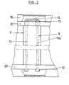
- the heating wire 11 as can be seen in FIG. 2, is provided in the region of its ends with connection elements formed by plug sockets 12 for corresponding supply and disposal cables.
- the heating line 9 has two branches 13 and 13a, which run parallel to one another and are connected in series in terms of the current flow, as FIG. 2 also shows.
- the heating line 9 simply forms a loop with two parallel branches which are connected to one another by an arch 14 in the region of a cylinder end face.
- the heating line 9 can simply be formed by a one-piece, approximately U-shaped shaped piece. If the two branches 13 or
- the branches 13 and 13a of the heating line 9 are fixed on mutually movable cylinder parts, a removable bend 14 can be advantageous, so that with corresponding movements, for example in the case of the tensioning or relaxing process, no constraining forces can occur.
- the branches 13 and 13a can be provided on the arch side with connecting elements formed here by plug sockets 15, onto which the arch 14 provided with corresponding counterparts can be attached.
- a corresponding excess length would have to be provided in the region of the arch 14 in order to avoid constraining forces.
- the heating wire forming the heating line 9 can simply be inserted into the tensioning slot 7 or glued to the radially outer end faces of the tensioning flaps 6. In this case, the heating wire is practically embedded in the material forming the filling 8, so that when the heating wire is activated, the filling 8 is heated quickly.
- the heating line 9 can expediently be designed in the form of a film cable which has a heating conductor embedded in an adhesive film.
- the tensioning flaps 6, as can best be seen from FIG. 1, are provided in the region of their radially outer ends with a channel 16 which extends over the entire length of the flap and into which a heating line 9, here in the form of an insulation jacket 10, is provided Heating wire 11, can be inserted.
- Each channel 16 can be assigned a heating wire loop, which is provided at its ends with plugs 12 for connecting supply and disposal cables.
- the two channels 16 of the two clamping flaps 6, which are arranged opposite one another at the same height, are each a branch 13 or 13a of the heating line forming a single loop 9 assigned, which results in a particularly compact channel cross section.
- an asbestos strip 17 is placed in each of the channels 16, which shields the heating line 9 inwards.
- the channels 16 are covered towards the clamping slot 7 by means of a cover plate 18.
- the branches of the heating line 9 arranged in the closed channels 16 are reliably protected against damage or contamination, which means that a long service life can be expected.
- a heating medium could also be used to form a heating line, e.g. B. with a hot gas, etc., can be acted upon pipeline provided the use of electric current should raise safety concerns.
- cover hoods 19 are provided in the area of the cylinder end faces, which protect the sockets 12 and 15 and possibly exposed parts of the heating line 9, in the present case the bend 14.
- the cover hoods 19 can simply be attached to the support rings 20 provided on the end face.
- the winding plate 1 can only be removed from the cylinder when the hooking claws 5 are exposed.
- the filling 8 of the clamping slot 7 must be removed or in any case weakened in such a way that the movable beak edge 4 can be displaced with respect to the stationary beak edge 3.
- the heating line 9 installed on the cylinder side is activated. The heat given off by this gives way to the filling 8 that the movable beak edge 4 is movable. In the course of this movement, the softened filling 8 is pulled apart and sheared off as a result of the transverse forces which become effective here. If this should not yet be fully achieved by moving the beak edge 4, a corresponding shearing off results in any case when the corresponding suspension claw 5 is removed.
- the filling 8 which can be softened or melted by means of the heating line 9 can have been introduced into the tensioning slot 7 by customary methods.
- the radially inner boundary of the clamping slot 8 can simply form a sealing strip 23 inserted into a corresponding groove of the clamping strips 6 and arranged radially inside the heating line 9, so that there is a mold cavity which is closed radially inwards.
Landscapes
- Engineering & Computer Science (AREA)
- Mechanical Engineering (AREA)
- Heating, Cooling, Or Curing Plastics Or The Like In General (AREA)
- Printing Plates And Materials Therefor (AREA)
- Manufacture Or Reproduction Of Printing Formes (AREA)
- Shaping Of Tube Ends By Bending Or Straightening (AREA)
Abstract
Description
- Die Erfindung betrifft gemäß eines ersten Erfindungsgedankens ein Verfahren zum Freilegen eines den Einhängklauen von Tiefdruckwickelplatten zugeordneten, formzylinderseitigen Spannschlitzes, der mittels eines Dichtstreifens nach radial innen abgedichtet und radial außerhalb des Dichtstreifens mit einer aus hartem Material bestehenden Füllung versehen ist. Ein weiterer Erfindungsgedanke geht auf eine vorteilhafte Vorrichtung zur Durchführung dieses Verfahrens.
- Bei der Verwendung von Wickelplatten im Tiefdruck ergibt sich praktisch eine Unterbrechung des Zylinderumfangs in Form eines schmalen Spannschlitzes, der zur Erzielung einer glatten Zylinderoberfläche und damit eines ruhigen Rakelverhaltens mit einem geeigneten Füllmaterial ausgefüllt werden muß. Die bekannten Vorschläge zielen nun darauf ab, als Füllmaterial eine aushärtende Masse, z.B. Amalgam oder Kunststoffe, zu verwenden, die mittels eines Spritzverfahrens einbringbar ist. Zum Abnehmen der Wickelplatten müssen die Einhängklauen freigelegt sein. In diesem Zusammenhang war man bisher darauf angewiesen, die Schlitzfüllung mit Hilfe eines Meißels zu entfernen, was sich als sehr umständlich und zeitaufwendig erwiesen hat.
- Hiervon ausgehend ist es daher die Aufgabe der vorliegenden Erfindung unter Vermeidung der Nachteile der bekannten Anordnungen ein Verfahren gattungsgemäßer Art zu schaffen, das eine schnelle und bequeme Entfernung der Spannschlitzfüllung ermöglicht. Eine weitere Aufgabe der vorliegenden Erfindung besteht darin, gleichzeitig eine einfache und zuverlässige Vorrichtung zur Durchführung dieses Verfahrens zu schaffen.
- Die auf den verfahrensmäßigen Teil der Aufgabe sich beziehende erfindungsgemäße Lösung besteht darin, daß aus einem die Füllungrbei Wärmeeinwirkung zumindest erweichenden oder schmelzenden Kunststoff beim Freilegen des Spannschlitzes durch spannschlitzseitige Wärmeeinwirkung zum Erweichen bzw. Schmelzen gebracht wird.
- Die schlitzseitige Erwärmung des Füllungsmaterials gewährleistet eine einfache Entfernung der Füllung. Durch Überführen des die Füllung bildenden Kunststoffs in eine weiche, teigige Phase kann die durch die Füllung an sich gewährleistete gegenseitige Verbindung der den Spannschlitz seitlich begrenzenden Schnabelkanten bzw. der diese übergreifenden Einhängklauen so geschwächt werden, daß die den Schnabelkanten zugeordnete Spannvorrichtung in Entspannrichtung betätigt werden kann, wobei vielfach die Füllung bereits durchreißt und damit die hierdurch bewirkte Verbindung der Schnabelkanten aufgelöst wird, bzw. jedenfalls eine solche Beweglichkeit erreicht wird, daß eine Entfernung der Wickelplatten möglich ist.
- Die auf den vorrichtungsmäßigen Teil der Aufgabe sich beziehende, erfindungsgemäße Lösung besteht darin, daß im Bereich des Spannschlitzes bzw. der diesen begrenzenden Wandungen mindestens eine Heizleitung vorgesehen ist, die von einer Zylinderstirnseite her mit Heizenergie beaufschlagbar ist.
- Ein derart ausgestatteter Tiefdruckformzylinder gestattet eine einfache schlitzseitige Beheizung des Schlitzmaterials und kann daher die Handhabung der bei Wärmeeinwirkung aufweichenden bzw. schmelzenden Füllung sehr erleichtern. Im Bereich der Zylinderstirnseite besteht in der Regel eine gute Zugänglichkeit, was den Anschluß der Heizleitung an eine entsprechende Energieversorgung sehr einfach gestalten kann.
- In vorteilhafter Weiterbildung der übergeordneten Maßnahmen kann die Heizleitung eine Schleife mit zwei parallel verlegten, in Serie geschalteten Ästen aufweisen, die im Bereich einer Zylinderstirnseite durch einen Bogen miteinander verbunden sind und an ihrer im Bereich der jeweils gegenüberliegenden Zylinderstirnseite liegenden Enden Anschlußelemente für entsprechende Ver- bzw. Entsorgungsleitungen aufweist. Hierbei ist in vorteilhafter Weise sichergestellt, daß die Heizleitung sowohl versorgungsseitig als auch entsorgungsseitig von einer Zylinderstirnseite her bedienbar ist, was den Anschluß an eine entsprechende Energieversorgung sehr erleichtern und vereinfachen kann und gleichzeitig in vorteilhafter Weise eine große Heizleitungslänge ergibt.
- Gemäß einer besonders zu bevorzugenden Fortbildung der übergeordneten Maßnahmen kann die Heizleitung einen mit elektrischem Strom beaufschlagbaren Heizdraht aufweisen. Eine Anordnung dieser Art ergibt in vorteilhafter Weise eine elektrische Widerstandsheizung, was eine besonders einfache Fernversorgung mit Hilfe elektrischer Kabel gewährleistet und gleichzeitig auf einfache Weise vergleichsweise hohe Temperaturen ermöglicht.
- Eine weitere vorteilhafte Maßnahme kann darin bestehen, daß die Heizleitung in einem zugeordneten, vorzugsweise schlitzseitig verschlossenen Kanal aufgenommen ist, was eine geschützte Unterbringung der Heizleitung ermöglicht, die somit immer wieder verwendbar ist.
- In weiterer Fortbildung dieser Maßnahmen kann der die Heizleitung aufnehmende Kanal mittels einer Asbestleiste oder dergleichen nach radial innen wärmevisoliert sein. Diese Maßnahme ergibt in vorteilhafter Weise eine Verstärkung des Wärmeflusses zum Spannschlitz und damit zum Füllungsmaterial hin.
- Weitere vorteilhafte Ausgestaltungen und zweckmäßige Fortbildungen der übergeordneten Maßnahmen ergeben sich aus der nachstehenden Beschreibung eines Ausführungsbeispiels anhand der Zeichnung in Verbindung mit den restlichen Unteransprüchen.
- In der Zeichnung zeigen:
- Figur 1 einen Radialschnitt durch einen mit Wickelplatten versehenen Tiefdruckformzylinder und
- Figur 2 eine Draufsicht auf den mit Wickelplatten versehenen Tiefdruckformzylinder gemäß Figur 1.
- Der der Figur 1 zugrunde liegende, zur Aufnahme von Wickelplatten 1 geeignete Tiefdruckformzylinder besitzt mindestens eine seinen Umfang unterbrechende Grube 2, die durch seitliche Schnabelkatten 3 bzw. 4 begrenzt ist, an denen die Einhängklauen 5 der Wickelplatte bzw. -platten 1 einhängbar sind. Die Einhängklauen 5 werden mittels durchgehender Klemmleisten 6, die mittels einer nicht näher dargestellten Exzenterwelle oder dergleichen betätigbar sein können, an die jeweils zugeordnete Schnabelkante 3 bzw. 4 angepreßt. Eine der Schnabelkanten 3 bzw. 4 kann zur Erleichterung des Einhängens der Einhängklauen 5 in radialer Richtung ein- und ausschwenkbar sein. Zum Spannen der Wickelplatte bzw. -platten 1 werden die Schnabelkanten 3 bzw. 4 aufeinander zubewegt. Hierzu kann die eine Schnabelkante bezüglich der Zylinderachse stationär und die andere Schnabelkante bezüglich der Zylinderachse drehbar angeordnet sein.
- Die Schnabelkanten 3 bzw. 4 liegen auch in dem der Figur 1 zugrunde liegenden Spannzustand nicht aneinander an, so daß sich ein von den Schnabelkanten 3 bzw. 4 bzw. von den diese übergreifenden Einhängklauen 5 seitlich begrenzter, nach radial außen offener Spannschlitz 7 ergibt, der zur Erzielung einer glatten Zylinderoberfläche durch eine Füllung 8 ausgefüllt ist. Die Füllung 8 besteht aus einem unter Wärmeeinwirkung weich bzw. teigig werdenden Kunststoff, z. B. aus einem wärme- oder lichtgehärtetem Polymer, etwa einem Acrylat-Harz. Zur Bewerkstelligung einer möglichen Wärmeeinwirkung auf das Füllungsmaterial ist der Zylinder mit einer Heizeinrichtung versehen.
- Die Heizeinrichtung besteht im dargestellten Ausführungsbeispiel einfach aus einer über die ganze Zylinderbreite sich erstreckenden Heizleitung 9 hier einfach in Form eines mit einer wärmebeständigen Isolation 10 versehen Heizdrahts 11, der zur Bildung einer elektrischen Widerstandsheizung mit elektrischem Strom beaufschlagbar ist. Hierzu ist der Heizdraht 11, wie Figur 2 erkennen läßt, im Bereich seiner Enden mit durch Steckbuchsen 12 gebildeten Anschlußelementen für entsprechende Ver- bzw. Entsorgungskabel versehen.
- Die Heizleitung 9 weist im dargestellten Ausführungsbeispiel, wie Figur 2 weiter erkennen läßt, zwei parallel zueinander verlaufende Aste 13 bzw. 13a auf, die stromführungsmäßig in Serie liegen. Hierzu bildet die Heizleitung 9 einfach eine Schleife mit zwei parallelen Ästen, die im Bereich einer Zylinderstirnseite durch einen Bogen 14 miteinander verbunden sind. Hierzu kann die Heizleitung 9 einfach durch ein einstückiges, etwa U-förmiges Formstück gebildet werden. Sofern die beiden Äste 13 bzw.
- 13a der Heizleitung 9 auf gegeneinander bewegbaren Zylinderteilen fixiert sind, kann ein abnehmbarer Bogen 14 vorteilhaft sein, so daß bei entsprechenden Bewegungen etwa im Falle des Spann- bzw. Entspannvorgangs keine Zwangskräfte auftreten können. Hierzu können die Äste 13 bzw. 13a bogenseitig mit hier durch Steckbuchsen 15 gebildeten Verbindungselementen versehen sein, auf die der mit entsprechenden Gegenstücken versehene Bogen 14 aufsteckbar ist. Im Falle einer einteiligen Ausführung müßte zur Vermeidung von Zwangskräften im Bereich des Bogens 14 eine entsprechende Überlänge vorgesehen sein.
- Der die Heizleitung 9 bildende Heizdraht kann einfach in den Spannschlitz 7 eingelegt bzw. auf die radial äußeren Stirnseiten der Spannklappen 6 aufgeklebt sein. In diesem Fall ist der Heizdraht praktisch in das die Füllung 8 bildende Material eingebettet, so daß bei einer Aktivierung des Heizdrahts eine schnelle Beheizung der Füllung 8 stattfindet. Zweckmäßig kann die Heizleitung 9 dabei in Form eines Folienkabels ausgebildet sein, das einen in eine Klebefolie eingebetteten Heizleiter besitzt. Im dargestellten Ausführungsbeispiel sind die Spannklappen 6, wie am besten aus Figur 1 erkennbar ist, im Bereich ihrer radial äußeren Enden mit jeweils einem über die ganze Klappenlänge durchgehenden Kanal 16 versehen, in den eine Heizleitung 9, hier in Form eines mit einem Isolationsmantel 10 versehenen Heizdrahts 11, einlegbar ist. Dabei kann jedem Kanal 16 eine Heizdrahtschleife zugeordnet sein, die an ihren Enden mit Stechbuchsen 12 zum Anschließen von Ver- und Entsorgungskabeln versehen ist. Im dargestellten Ausführungsbeispiel ist den beiden, auf gleicher Höhe einander gegenüberliegend angeordneten Kanälen 16 der beiden Spannklappen 6 jeweils ein Ast 13 bzw. 13a der eine Einfachschleife bildenden Heizleitung 9 zugeordnet, was einen besonders kompakten Kanalquerschnitt ergibt. Zur Vermeidung eines nach radial innen gerichteten Wärmeflusses ist in die Kanäle 16 jeweils eine Asbestleiste 17 eingelegt, welche die Heizleitung 9 nach innen abschirmt. Die Kanäle 16 sind zum Spannschlitz 7 hin mittels einer Deckplatte 18 abgedeckt. Es wäre jedoch auch denkbar, die Kanäle 16 einfach als Bohrungen auszubilden. Die in den geschlossenen Kanälen 16 angeordneten Äste der Heizleitung 9 sind gegen Beschädigungen bzw. Verunreinigungen zuverlässig geschützt, was eine hohe Lebensdauer erwarten läßt.
- Anstelle eines eine elektrische Widerstandsheizung bildenden Heizdrahts könnte zur Bildung einer Heizleitung auch eine mit einem Heizmedium, z. B. mit einem heißen Gas etc., beaufschlagbare Rohrleitung vorgesehen sein, sofern die Verwendung von elektrischem Strom auf sicherheitstechnische Bedenken stoßen sollte. Im dargestellten Ausführungsbeispiel sind aus Sicherheitsgründen, wie Figur 2 am besten zeigt, im Bereich der Zylinderstirnseiten angeordnete Abdeckhauben 19 vorgesehen, welche die Steckbuchsen 12 bzw. 15 und evtl. freiliegende Teile der Heizleitung 9, im vorliegenden Fall den Bogen 14, schützen. Die Abdeckhauben 19 können einfach an den stirnseitig vorgesehenen Stützringen 20 befestigt sein.
- Die Wickelplatte 1 kann vom Zylinder nur abgenommen werden, wenn die Einhängklauen 5 freiliegen. Hierzu muß die Füllung 8 des Spannschlitzes 7 entfernt oder jedenfalls so geschwächt werden, daß die bewegbare Schnabelkante 4 gegenüber der stationären Schnabelkante 3 verschoben werden kann. Hierzu wird die zylinderseitig eingebaute Heizleitung 9 aktiviert. Die von dieser abgegebene Wärme weicht die Füllung 8 so weit auf, daß die bewegbare Schnabelkante 4 bewegbar ist. Im Verlauf dieser Bewegung wird die aufgeweichte Füllung 8 auseinandergezogen und infolge der hierbei wirksam werdenden Querkräfte abgeschert. Sofern dies durch Bewegung der Schnabelkante 4 noch nicht voll err_eicht werden sollte, ergibt sich eine entsprechende Abscherung auf jeden Fall beim Herausnehmen der entsprechenden Einhängklaue 5.
- Die mittels der Heizleitung 9 aufweichbare bzw. aufschmelzbare Füllung 8 kann in den Spannschlitz 7 nach üblichen Methoden eingebracht worden sein. Die radial innere Begrenzung des Spannschlitzes 8 kann dabei einfach ein in eine entsprechende Nut der Spannleisten 6 eingelegter, radial innerhalb der Heizleitung 9 angeordneter Dichtstreifen 23 bilden, so daß ein nach radial innen geschlossener Formhohlraum gegeben ist.
Claims (10)
Applications Claiming Priority (4)
| Application Number | Priority Date | Filing Date | Title |
|---|---|---|---|
| DE3312343 | 1983-04-06 | ||
| DE3312343 | 1983-04-06 | ||
| DE3337111 | 1983-10-12 | ||
| DE3337111A DE3337111C2 (de) | 1983-04-06 | 1983-10-12 | Tiefdruckformzylinder |
Publications (3)
| Publication Number | Publication Date |
|---|---|
| EP0122217A2 true EP0122217A2 (de) | 1984-10-17 |
| EP0122217A3 EP0122217A3 (en) | 1985-10-23 |
| EP0122217B1 EP0122217B1 (de) | 1988-01-27 |
Family
ID=25809742
Family Applications (1)
| Application Number | Title | Priority Date | Filing Date |
|---|---|---|---|
| EP84710010A Expired EP0122217B1 (de) | 1983-04-06 | 1984-03-29 | Verfahren und Vorrichtung zum Freilegen eines Spannschlitzes eines Tiefdruckformzylinders |
Country Status (2)
| Country | Link |
|---|---|
| EP (1) | EP0122217B1 (de) |
| DE (2) | DE3337111C2 (de) |
Families Citing this family (3)
| Publication number | Priority date | Publication date | Assignee | Title |
|---|---|---|---|---|
| DE3644501A1 (de) * | 1986-12-24 | 1988-07-07 | Koenig & Bauer Ag | Stuetzeinrichtung in einer zylindergrube |
| DE3928640A1 (de) * | 1989-08-30 | 1991-03-14 | Roland Man Druckmasch | Gummituchzylinder fuer bogenrotations-offsetdruckmaschinen |
| EP2683064A1 (de) * | 2012-07-03 | 2014-01-08 | Alstom Technology Ltd. | Verfahren zur Beseitigung von Stangen oder Spulen aus Schlitzen einer elektrischen Maschine |
Family Cites Families (4)
| Publication number | Priority date | Publication date | Assignee | Title |
|---|---|---|---|---|
| FR1367860A (fr) * | 1963-08-13 | 1964-07-24 | Crabtree & Sons Ltd R | Perfectionnement aux machines à imprimer rotatives |
| DE2545618A1 (de) * | 1975-10-11 | 1977-04-21 | Frankenthal Ag Albert | Formzylinder fuer tiefdruck mit einer magnetisch aufgespannten wickelplatte |
| DE3049143A1 (de) * | 1980-12-24 | 1982-07-22 | M.A.N.- Roland Druckmaschinen AG, 6050 Offenbach | Formzylinder fuer bogenrotations-tiefdruck-druckmaschinen |
| DE3304946A1 (de) * | 1983-02-12 | 1984-10-11 | Albert-Frankenthal Ag, 6710 Frankenthal | Vorrichtung zum erleichtern des abnehmens von wickelplatten vom formzylinder einer tiefdruckmaschine |
-
1983
- 1983-10-12 DE DE3337111A patent/DE3337111C2/de not_active Expired
-
1984
- 1984-03-29 DE DE8484710010T patent/DE3468995D1/de not_active Expired
- 1984-03-29 EP EP84710010A patent/EP0122217B1/de not_active Expired
Also Published As
| Publication number | Publication date |
|---|---|
| DE3337111A1 (de) | 1984-10-11 |
| EP0122217B1 (de) | 1988-01-27 |
| EP0122217A3 (en) | 1985-10-23 |
| DE3337111C2 (de) | 1985-05-09 |
| DE3468995D1 (en) | 1988-03-03 |
Similar Documents
| Publication | Publication Date | Title |
|---|---|---|
| DE2607058A1 (de) | Verfahren und form zum herstellen von geformten kabel-spleisstellen | |
| DE69014859T2 (de) | Spleissverschlüsse. | |
| DE2432670A1 (de) | Vorrichtung zum trennen von elektrischen verbindern von tragstreifen und zum andruecken derselben an draehte | |
| DE2039917A1 (de) | Schweissverfahren fuer Kabelmaentel unter Verwendung einer waermeaufschrumpfbaren Waermeabschirmung | |
| EP0122217B1 (de) | Verfahren und Vorrichtung zum Freilegen eines Spannschlitzes eines Tiefdruckformzylinders | |
| EP0051109A1 (de) | Vorrichtung zum Verbinden und Umhüllen von Kabelverbindungen, insbesondere von Breitband-Kommunikationskabeln | |
| DE2651014C2 (de) | Klemme für einadrige elektrische Leiter | |
| EP0124695B1 (de) | Klemme und Muffe für eine derartige Klemme | |
| DE2800871C3 (de) | Anlage zum Stranggießen von Drähten | |
| DE1046133B (de) | Zange zum Abisolieren von elektrischen Leitungen | |
| DE1564416A1 (de) | Verfahren und Vorrichtung zum Herstellen von Halbleitern | |
| DE2705829B2 (de) | Verfahren und Vorrichtung zum Abisolieren eines Endabschnittes eines litzenförmigen Leiters | |
| DE2927558C2 (de) | Anschlußleitung für ein elektrisches Gerät | |
| DE3527658C2 (de) | ||
| DE4019314C2 (de) | ||
| DE2723851C2 (de) | Verfahren zum Abisolieren der Enden einer Flachleiter-Bandleitung | |
| DE102016121909A1 (de) | Dichtung von Leitungsverbindern | |
| DE8214042U1 (de) | Elektrischer Lötkolben | |
| DE102015104537B4 (de) | Elektrische Verbindung in Kabelbäumen für Fahrzeuge sowie Verfahren zur Herstellung einer solchen Verbindung | |
| DE69610247T2 (de) | Verfahren zum Bereitstellen eines Kabelendes sowie Muffe für Hochspannungskabel | |
| DE2628151A1 (de) | Verfahren zum anbringen eines schutzkontaktes an einem kabel und schutzvorrichtung hierfuer | |
| DE69302015T2 (de) | Verfahren und vorrichtung zum herstellen eines umhüllten leitungsbündels | |
| DE2165442A1 (de) | Steckerverbindung fuer elektrische leitungen und verfahren zur herstellung der steckerverbindung.- | |
| EP1712117B1 (de) | Landwirtschaftliche Verteilmaschine | |
| EP0000731B1 (de) | Verfahren zur Herstellung von Abzweigungen an einem isolierten elektrischen Kabel |
Legal Events
| Date | Code | Title | Description |
|---|---|---|---|
| PUAI | Public reference made under article 153(3) epc to a published international application that has entered the european phase |
Free format text: ORIGINAL CODE: 0009012 |
|
| AK | Designated contracting states |
Designated state(s): CH DE FR GB IT LI |
|
| PUAL | Search report despatched |
Free format text: ORIGINAL CODE: 0009013 |
|
| AK | Designated contracting states |
Designated state(s): CH DE FR GB IT LI |
|
| 17P | Request for examination filed |
Effective date: 19860205 |
|
| RAP1 | Party data changed (applicant data changed or rights of an application transferred) |
Owner name: BASF AKTIENGESELLSCHAFT |
|
| 17Q | First examination report despatched |
Effective date: 19870622 |
|
| GRAA | (expected) grant |
Free format text: ORIGINAL CODE: 0009210 |
|
| AK | Designated contracting states |
Kind code of ref document: B1 Designated state(s): CH DE FR GB IT LI |
|
| ITF | It: translation for a ep patent filed | ||
| REF | Corresponds to: |
Ref document number: 3468995 Country of ref document: DE Date of ref document: 19880303 |
|
| GBT | Gb: translation of ep patent filed (gb section 77(6)(a)/1977) | ||
| ET | Fr: translation filed | ||
| PLBE | No opposition filed within time limit |
Free format text: ORIGINAL CODE: 0009261 |
|
| STAA | Information on the status of an ep patent application or granted ep patent |
Free format text: STATUS: NO OPPOSITION FILED WITHIN TIME LIMIT |
|
| 26N | No opposition filed | ||
| ITTA | It: last paid annual fee | ||
| PGFP | Annual fee paid to national office [announced via postgrant information from national office to epo] |
Ref country code: FR Payment date: 19930217 Year of fee payment: 10 |
|
| PGFP | Annual fee paid to national office [announced via postgrant information from national office to epo] |
Ref country code: CH Payment date: 19930222 Year of fee payment: 10 |
|
| PGFP | Annual fee paid to national office [announced via postgrant information from national office to epo] |
Ref country code: DE Payment date: 19930313 Year of fee payment: 10 |
|
| PGFP | Annual fee paid to national office [announced via postgrant information from national office to epo] |
Ref country code: GB Payment date: 19930315 Year of fee payment: 10 |
|
| PG25 | Lapsed in a contracting state [announced via postgrant information from national office to epo] |
Ref country code: GB Effective date: 19940329 |
|
| PG25 | Lapsed in a contracting state [announced via postgrant information from national office to epo] |
Ref country code: LI Effective date: 19940331 Ref country code: CH Effective date: 19940331 |
|
| GBPC | Gb: european patent ceased through non-payment of renewal fee |
Effective date: 19940329 |
|
| PG25 | Lapsed in a contracting state [announced via postgrant information from national office to epo] |
Ref country code: FR Effective date: 19941130 |
|
| REG | Reference to a national code |
Ref country code: CH Ref legal event code: PL |
|
| PG25 | Lapsed in a contracting state [announced via postgrant information from national office to epo] |
Ref country code: DE Effective date: 19941201 |
|
| REG | Reference to a national code |
Ref country code: FR Ref legal event code: ST |