EP0122236A2 - Halter für Flachsicherungen - Google Patents
Halter für Flachsicherungen Download PDFInfo
- Publication number
- EP0122236A2 EP0122236A2 EP84830101A EP84830101A EP0122236A2 EP 0122236 A2 EP0122236 A2 EP 0122236A2 EP 84830101 A EP84830101 A EP 84830101A EP 84830101 A EP84830101 A EP 84830101A EP 0122236 A2 EP0122236 A2 EP 0122236A2
- Authority
- EP
- European Patent Office
- Prior art keywords
- holder
- pair
- elements
- sides
- blocking
- Prior art date
- Legal status (The legal status is an assumption and is not a legal conclusion. Google has not performed a legal analysis and makes no representation as to the accuracy of the status listed.)
- Granted
Links
Images


Classifications
-
- H—ELECTRICITY
- H01—ELECTRIC ELEMENTS
- H01H—ELECTRIC SWITCHES; RELAYS; SELECTORS; EMERGENCY PROTECTIVE DEVICES
- H01H85/00—Protective devices in which the current flows through a part of fusible material and this current is interrupted by displacement of the fusible material when this current becomes excessive
- H01H85/02—Details
- H01H85/20—Bases for supporting the fuse; Separate parts thereof
- H01H85/2045—Mounting means or insulating parts of the base, e.g. covers, casings
-
- H—ELECTRICITY
- H01—ELECTRIC ELEMENTS
- H01H—ELECTRIC SWITCHES; RELAYS; SELECTORS; EMERGENCY PROTECTIVE DEVICES
- H01H85/00—Protective devices in which the current flows through a part of fusible material and this current is interrupted by displacement of the fusible material when this current becomes excessive
- H01H85/02—Details
- H01H85/20—Bases for supporting the fuse; Separate parts thereof
- H01H85/203—Bases for supporting the fuse; Separate parts thereof for fuses with blade type terminals
- H01H85/2035—Bases for supporting the fuse; Separate parts thereof for fuses with blade type terminals for miniature fuses with parallel side contacts
-
- H—ELECTRICITY
- H01—ELECTRIC ELEMENTS
- H01H—ELECTRIC SWITCHES; RELAYS; SELECTORS; EMERGENCY PROTECTIVE DEVICES
- H01H85/00—Protective devices in which the current flows through a part of fusible material and this current is interrupted by displacement of the fusible material when this current becomes excessive
- H01H85/02—Details
- H01H85/20—Bases for supporting the fuse; Separate parts thereof
- H01H85/201—Bases for supporting the fuse; Separate parts thereof for connecting a fuse in a lead and adapted to be supported by the lead alone
Definitions
- the present invention relates to a holder for plate fuses, in particular for cars.
- fuses of different shapes and sizes, connected in series within the circuit, are employed in several appliances in order to protect the various apparatus of an electrical system, for example of cars.
- Fuse holders bearing a pair of receptacles connected to the circuit and in which the ends of appropriate fuses are inserted, are employed in order to allow an easy replacement of the melted fuses.
- the object of the present invention is to provide, at a low prime cost, an appropriately insulated holder for plate fuses apt to contain a pair of plane receptacles and to be associated to one or more holders of the same type in order to house, in a close structure, all the fuses protecting an electrical system.
- the present invention provides a fuse holder obtained from a single moulded piece for containing and keeping in position two metal receptacles, into which the electric contacts of plate type fuses can be inserted, and provided with means for its connection to other holders of the same type and/or to fixed supporting structures.
- the present invention it is possible to rapidly and easily assemble and disassemble the holder and the metal receptacles therein contained. It is also possible to rapidly and easily connect and disconnect two or more assembled holders of the invention respectively for their reciprocal connection or disconnection or for their connection with or disconnection from fixed supporting structures.
- the present invention provides a holder for plate fuses, in particular for cars, consisting of a shaped plate in dielectric plastic comprising two sides and a central portion, which are delimited from each other by t MO parallel folding lines in reduced thickness material, said sides being provided with ribbings for housing and keeping in position, electrically insulated each other, a pair of plane metal receptacles, said sides being furthermore foldable each towards the other so as to hold and to allow the blocking of the metal receptacles, each side laterally bearing elastic elements and corresponding seats for blocking the sides in the closed position of the holder as well as further elastic elements and further corresponding seats for connecting and packing two or more fuse holders of the invention placed side by side.
- an anchor plate which bears a pair of seats for housing and engaging the pair of further elastic elements projecting from a holder, said plate being also provided with means for constraining it to a fixed supporting structure, for example to the body of a car or the like.
- said elastic elements and the corresponding seats for blocking the holder in the closed position consist respectively of a pair of hook elements projecting from the upper part of one side towards the inside of the holder and of a pair of step hollows obtained in the corresponding areas of the opposite side and apt to engage said elastic hook elements during the closing of the sides for forming the holder.
- the elastic elements and the corresponding seats for packing two or more holders consist respectively of a pair of hook elements projecting towards the outside of the holder in a direction perpendicular to the plane of the side and placed on the same side bearing the step hollows designed for blocking the holder in the closed position and of a pair of step hollows obtained in the corresponding areas of the opposite side, below the elastic hook elements designed for blocking the holder in the closed position, and apt to engage the hook elements projecting from the outer side of a further holder to be packed.
- the side bearing the pair of hook elements designed for blocking the holder in the closed position also bears a further elastic element, placed in its lower inner part, in the middle as to the width, and preferably consisting of a hook element, which is designed to be engaged in a corresponding seat obtained in the opposite side and preferably consisting of a step hollow, for a better blocking of the holder in the closed position and which constitutes, together with complementary ribbings which are present on the two sides and designed for forming a slide in order to close the holder in a correct position, an insulating partition for the electric contacts.
- the pair of seats provided in the anchor plate advantageously consists of a pair of step hollows apt to engage the pair of elastic hook elements projecting towards the outside of a single holder or of a holder connected to one or more holders packed according to the invention.
- Said preferred embodiment of the invention furthermore provides, on the inner surfaces of the sides, ribbings having a different relief for housing and keeping in seat the metal receptacles as well as appropriately prearranged outlet grooves for the wires, which allow the holder of the invention to contain either plane metal receptacles having a plate orthogonal to the receptacle itself, or plane metal receptacles having a wire orthogonal to the receptacle.
- the inner surfaces of the sides are provided with ribbings for housing and keeping in position, electrically insulated from each other, a pair of metal receptacles of the type called "Faston” or the like.
- the inner surfaces of the sides also bear pins and sleeves designed to fit each other for centering the two opposite sides in the correct position when closing the holder.
- the elastic elements and the corresponding seats for blocking the holder in the closed position respectively consist of a pair of staple elements projecting from the upper part of one side towards the inside of the holder and of a pair of tooth elements obtained in the corresponding areas of the opposite side and apt to engage said staple elements when closing the sides for forming the holder.
- the elastic elements and the corresponding seats for packing two or more holders consist respectively of a pair of staple elements projecting towards the outside of the holder in a direction perpendicular to the plane of the side and placed on the same side bearing the tooth elements designed for blocking the holder in the closed position,and of a pair of tooth elements obtained in the corresponding areas of the opposite side, below the staple elements designed for blocking the holder in the closed position, and apt to engage the staple elements projecting from the outer side of a further holder to be packed.
- the pair of seats provided in the anchor plate advantageously consists of a pair of tooth elements apt to engage the pair of staple elements projecting towards the outside of a single holder or of a holder connected to one or more holders packed according to the invention.
- the holder according to said further embodiment of the invention furthermore provides a middle partition, lengthwhise arranged, and appropriate lateral openings placed in its lower part for allowing the passage of the wires for the electric connection of the metal receptacles therein contained.
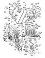
- the fuse holder 1 of the invention according to a preferred embodiment thereof consists of a shaped plate, in insulating plastic, which can be folded along the parallel lines 2, 3 having a reduced thickness and delimitating two sides 1a, 1b as well as a central portion 1c preferably bearing an opening 1d.
- the side 1b furthermore bears, in its lower inner part and in a central position with respect to the width, a hook element 9 designed for engaging, when closing the holder, in the corresponding step hollow 10 of the side 1a for a better blocking of the holder itself in the closed position.
- the side 1b provides ribbings having a higher relief 11, 11b for housing the metal receptacles, while ribbings having a lower relief 12, 12b are provided on both sides 1a, 1b for keeping in seat said metal receptacles.
- the side 1a provides a tooth relief 13 designed, when closing the holder, to be inserted between the ribbings 11b of the side 1b for a correct positioning of the two sides and to form, in the closed position of the holder and in co-operation with the hook element 9, an insulating partition for the electric contacts.
- Appropriate semicylindrical hollows 14 are laterally provided in the lower part of both sides 1a and 1b for allowing the wires, when present, to pass.
- Said receptacles 15 or 17 will be blocked, in the closed position of the holder, as to their slidings in a direction parallel to the ribbings having a higher relief 11b, for example during the insertion or the extraction of a plate fuse, by the lower transversal sections of the ribbings having a higher relief 4b as well as by the transversal ribbings having a lower relief 12b, and, as to their slidings in a direction parallel to the lines 2, 3 having a reduced thickness, by the ribbings having a higher relief 11b.
- a hole 1d is furthermore preferably obtained in order to allow the air for cooling the contacts and/or the fuses at the time of melting to pass.
- Figure 4 is shown the fuse holder 1 of Figure 1 housing two metal receptacles 15 with an orthogonal wire 16, which has been folded along the lines 2 and 3, closed and fixed by engaging the hook elements 6 in the corresponding step hollows 7. By the further engaging of the hook element 9 in the corresponding step hollow 10 there is obtained the optimum blocking of the mounted holder in the closed position.
- the tooth relief 13 is inserted between the ribbings 11b, thus allowing the correct positioning of the two sides 1a and 1b and preventing possible lateral slidings thereof.
- a plate fuse 19 is inserted, by its contact plates 19', into the receptacles 15 of the holder 1.
- Figure 4 is furthermore shown a second fuse holder 1' housing two metal receptacles with an orthogonal plate 17, mounted as above described and packed to the holder 1 by engaging its lower hook elements 5' into the step hollows 8 of the holder 1, said holder 1' presenting its step hollows 8' free for connecting further holders.
- the fixing of the holder, or of a group of packed fuse holders, to a fixed supporting structure, for example to the body of a car or the like, can be made using an anchor element of the type illustrated in Figure 5, in which a plate 20 is provided with a pair of lateral step hollows 21 designed to engage the hook element 5 of the fuse holder 1 and with a lower projection 22 for supporting the holder itself.
- the plate 20 can be fixed in the use position by means of an adhesive or of a bi-adhesive plate, or by means of screws.
- a pair of elastic tooth wedges 23 designed to be inserted and fixed in an appropriately shaped hole obtained in the body of the car or the like.
- said plate 20 will be provided with a projecting pin 24 or the like, which enters a corresponding hole in the body, in order to prevent the plate 20 from rotating.
- the fuse holder 101 of the invention according to a further embodiment thereof consists of a shaped plate, in insulating plastic, which can be folded along two parallel lines 102, 103 having a reduced thickness and delimiting two sides 101a, 101b as well as a central portion 101c.
- Sides 101a, 101b present lateral relief edges 104, interrupted in a portion next to the central portion 101c and opposite fixing elements 105, 106 consisting respectively of a sleeve 105 and of a pin 106, which can be inserted into said sleeve 105.
- Relief ribbings 107, 108 are furthermore provided on both sides 101a, 101b.
- the lateral relief edges 104 of the side 101a bear, in their upper parts, tooth elements 109 while, in correspondence to them, the lateral relief edges 104 of the side 101b bear staple elements 110.
- the lateral relief edges 104 of the side 101a bear the staple elements 111 while, in correspondence to them, the lateral relief edges 104 of the side 101b bear the tooth elements 112.
- the side 101b furthermore bears the partition 113 subdividing it into two portions.
- Said receptacles 114 are blocked, as to their slidings in a direction parallel to the partition 113, by said relief ribbings 107, 108.
- recesses 104a can be obtained with the purpose of facilitating the extraction of the fuse with fingers.
- FIG 8 there is illustrated the holder 101, housing two receptacles 114, which has been folded along the lines 102 and 103, closed and fixed by engaging the tooth elements 109 inside the corresponding staple elements 110.
- pins 106 When closing the holder, pins 106, inserted inside the sleeves 105, assure the centering of the coupling of the two sides 101a and 101b and prevent possible lateral slidings thereof.
- Figure 8 is furthermore shown a plate fuse 116 inserted, by its contact plates 117, into the receptacles 114.
- FIG 8 there is shown how a second fuse holder 101', with the fuse 116' inserted, is connected to the holder 101 by engaging its staple elements 111' beyond the tooth elements 112 of the holder 101 and presenting its tooth elements 112' free for the connection of further holders.
- the fixing of the holder 101, or of a group of packed fuse holders 101, to a fixed supporting structure, for example to the body of a car or the like, can be made using an anchor element of the type illustrated in Figure 9, in which a plate 118 is provided with a pair of lateral tooth elements 119 designed to couple with the staple elements 111 of the fuse holder 101, and with a lower projection 120 for supporting the holder 101.
- the plate 118 can be fixed in the use position as already described and illustrated with reference to Figure 5.
- the metal receptacles of the type "Faston" 114 or the like are kept in position, when a pressure is exerted for inserting the fuse 116, by the relief ribbings 108 against which the bent ends 114a of the receptacle 114 can lean.
- the fuse 116 is pulled for its extraction, the upper end of the receptacles 114, indicated with the reference 114b in Figure 7, leans against the ribbings 107, thus preventing the slipping of the receptacles 114 out of the holder.
- a different arrangement of the pins 105 and of the sleeves 106 in the holder 101 may be provided and two openings in the central portion 101c will be provided in order to allow the wires connected to the receptacles to pass.
- the holder according to the invention can be also applied, without any substantial change or variation, to the electrical connection of two poles of an electric system. by substituting the fuse with a plate plug which may be joined or separated.
Landscapes
- Fuses (AREA)
Priority Applications (1)
| Application Number | Priority Date | Filing Date | Title |
|---|---|---|---|
| AT84830101T ATE44332T1 (de) | 1983-04-07 | 1984-04-02 | Halter fuer flachsicherungen. |
Applications Claiming Priority (4)
| Application Number | Priority Date | Filing Date | Title |
|---|---|---|---|
| ITMI1983U21450U IT8321450U1 (it) | 1983-04-07 | 1983-04-07 | Contenitore portafusibili per fusibili lamellari. |
| IT2145083U | 1983-04-07 | ||
| IT3564584U | 1984-03-14 | ||
| ITRM1984U35645U IT8435645U1 (it) | 1984-03-14 | 1984-03-14 | Contenitore portafusibili per fusibili lamellari. |
Publications (3)
| Publication Number | Publication Date |
|---|---|
| EP0122236A2 true EP0122236A2 (de) | 1984-10-17 |
| EP0122236A3 EP0122236A3 (en) | 1985-11-06 |
| EP0122236B1 EP0122236B1 (de) | 1989-06-28 |
Family
ID=26327899
Family Applications (1)
| Application Number | Title | Priority Date | Filing Date |
|---|---|---|---|
| EP19840830101 Expired EP0122236B1 (de) | 1983-04-07 | 1984-04-02 | Halter für Flachsicherungen |
Country Status (3)
| Country | Link |
|---|---|
| EP (1) | EP0122236B1 (de) |
| DE (1) | DE3478834D1 (de) |
| ES (1) | ES278632Y (de) |
Cited By (1)
| Publication number | Priority date | Publication date | Assignee | Title |
|---|---|---|---|---|
| EP1235246A3 (de) * | 2001-02-22 | 2004-05-26 | J.S.T. Mfg. Co., Ltd. | Halter für einen Sicherungseinsatz |
Families Citing this family (1)
| Publication number | Priority date | Publication date | Assignee | Title |
|---|---|---|---|---|
| DE202016100939U1 (de) | 2016-02-23 | 2016-04-12 | Lisa Dräxlmaier GmbH | Bauteilträger für eine Mehrzahl elektrischer Bauteile |
Family Cites Families (7)
| Publication number | Priority date | Publication date | Assignee | Title |
|---|---|---|---|---|
| FR1431137A (fr) * | 1964-02-27 | 1966-03-11 | Amp | Enveloppe élastique isolante pour connecteurs électriques |
| DE1490668A1 (de) * | 1964-09-23 | 1969-06-04 | Siemens Ag | Elektrischer Anschlussstecker |
| GB1210844A (en) * | 1968-04-24 | 1970-11-04 | Amp Inc | Electrical component holder |
| GB1397249A (en) * | 1971-12-30 | 1975-06-11 | Lucas Electrical Co Ltd | Electrical connector arrangement |
| US4040703A (en) * | 1975-09-05 | 1977-08-09 | Amp Incorporated | Tri-lead cable connector |
| DE2825558C3 (de) * | 1978-06-10 | 1981-05-14 | Fa. Leopold Kostal, 5880 Lüdenscheid | Mehrfach-Streckverbindung für elektrische Leitungen,insbesondere in Kraftfahrzeugen |
| US4391485A (en) * | 1981-01-09 | 1983-07-05 | Mcgraw-Edison Company | In-line fuse holder for miniature plug-in fuse |
-
1984
- 1984-04-02 DE DE8484830101T patent/DE3478834D1/de not_active Expired
- 1984-04-02 EP EP19840830101 patent/EP0122236B1/de not_active Expired
- 1984-04-06 ES ES1984278632U patent/ES278632Y/es not_active Expired
Cited By (1)
| Publication number | Priority date | Publication date | Assignee | Title |
|---|---|---|---|---|
| EP1235246A3 (de) * | 2001-02-22 | 2004-05-26 | J.S.T. Mfg. Co., Ltd. | Halter für einen Sicherungseinsatz |
Also Published As
| Publication number | Publication date |
|---|---|
| EP0122236A3 (en) | 1985-11-06 |
| DE3478834D1 (en) | 1989-08-03 |
| EP0122236B1 (de) | 1989-06-28 |
| ES278632U (es) | 1984-10-16 |
| ES278632Y (es) | 1985-04-16 |
Similar Documents
| Publication | Publication Date | Title |
|---|---|---|
| CA1191221A (en) | Terminal bridging adapter | |
| US3850496A (en) | Connector block for hermetic motor compressor | |
| US4992062A (en) | Electrical connection device | |
| EP0170694A4 (de) | Elektrisches zwischengerät. | |
| GB2024541A (en) | Fuse assembly | |
| KR950034877A (ko) | 배터리장치 및 이 배터리장치가 장착된 전자기기 | |
| US6457995B1 (en) | Vehicle fuse block extenders | |
| RU2001105901A (ru) | Плавкий предохранитель и основание плавких предохранителей | |
| JPH07501919A (ja) | 母線カバー | |
| JPH08124639A (ja) | 電気接続箱用の中継端子 | |
| US4434548A (en) | Method of manufacturing plug-in electrical fuses | |
| US20030003808A1 (en) | Adapter with fuse and indicator and capable of being used as plug | |
| US6101079A (en) | Current and transient voltage protector | |
| US3467941A (en) | Duplex socket contact with breakoff tab | |
| US3333231A (en) | Receptacle assemblies | |
| EP0122236A2 (de) | Halter für Flachsicherungen | |
| US4192571A (en) | Electrical connector strain relief housing | |
| EP1339139A1 (de) | Steckverbinderanordnung für Zündsystem und Kurzschlussanordnung | |
| US4222627A (en) | Pullout fuse holder | |
| US6843668B2 (en) | Device for connecting an electrical load to an insulated power supply cable | |
| KR20030028760A (ko) | 단락 전기 커넥터 | |
| GB2263588A (en) | Junction box and bridging terminal | |
| JP7482933B2 (ja) | 導体アダプタを受けるための貫通開口部を有するプラガブルコネクタを備えた電気アセンブリ | |
| CN114824864B (zh) | 包括具有侧向部分的导电条的端子块 | |
| US4655536A (en) | Plug arrangement for electric cord set |
Legal Events
| Date | Code | Title | Description |
|---|---|---|---|
| PUAI | Public reference made under article 153(3) epc to a published international application that has entered the european phase |
Free format text: ORIGINAL CODE: 0009012 |
|
| AK | Designated contracting states |
Designated state(s): AT BE CH DE FR GB LI LU NL SE |
|
| PUAL | Search report despatched |
Free format text: ORIGINAL CODE: 0009013 |
|
| AK | Designated contracting states |
Designated state(s): AT BE CH DE FR GB LI LU NL SE |
|
| 17P | Request for examination filed |
Effective date: 19860328 |
|
| 17Q | First examination report despatched |
Effective date: 19871116 |
|
| GRAA | (expected) grant |
Free format text: ORIGINAL CODE: 0009210 |
|
| AK | Designated contracting states |
Kind code of ref document: B1 Designated state(s): AT BE CH DE FR GB LI LU NL SE |
|
| PG25 | Lapsed in a contracting state [announced via postgrant information from national office to epo] |
Ref country code: SE Effective date: 19890628 Ref country code: LI Effective date: 19890628 Ref country code: CH Effective date: 19890628 |
|
| REF | Corresponds to: |
Ref document number: 44332 Country of ref document: AT Date of ref document: 19890715 Kind code of ref document: T |
|
| REF | Corresponds to: |
Ref document number: 3478834 Country of ref document: DE Date of ref document: 19890803 |
|
| REG | Reference to a national code |
Ref country code: CH Ref legal event code: PL |
|
| ET | Fr: translation filed | ||
| PLBE | No opposition filed within time limit |
Free format text: ORIGINAL CODE: 0009261 |
|
| STAA | Information on the status of an ep patent application or granted ep patent |
Free format text: STATUS: NO OPPOSITION FILED WITHIN TIME LIMIT |
|
| PG25 | Lapsed in a contracting state [announced via postgrant information from national office to epo] |
Ref country code: LU Free format text: LAPSE BECAUSE OF NON-PAYMENT OF DUE FEES Effective date: 19900430 |
|
| 26N | No opposition filed | ||
| PGFP | Annual fee paid to national office [announced via postgrant information from national office to epo] |
Ref country code: GB Payment date: 19930330 Year of fee payment: 10 Ref country code: FR Payment date: 19930330 Year of fee payment: 10 |
|
| PGFP | Annual fee paid to national office [announced via postgrant information from national office to epo] |
Ref country code: BE Payment date: 19930414 Year of fee payment: 10 |
|
| PGFP | Annual fee paid to national office [announced via postgrant information from national office to epo] |
Ref country code: AT Payment date: 19930428 Year of fee payment: 10 |
|
| PGFP | Annual fee paid to national office [announced via postgrant information from national office to epo] |
Ref country code: NL Payment date: 19930430 Year of fee payment: 10 |
|
| PGFP | Annual fee paid to national office [announced via postgrant information from national office to epo] |
Ref country code: DE Payment date: 19930623 Year of fee payment: 10 |
|
| PG25 | Lapsed in a contracting state [announced via postgrant information from national office to epo] |
Ref country code: GB Effective date: 19940402 Ref country code: AT Effective date: 19940402 |
|
| PG25 | Lapsed in a contracting state [announced via postgrant information from national office to epo] |
Ref country code: BE Effective date: 19940430 |
|
| BERE | Be: lapsed |
Owner name: MENBER'S S.P.A. Effective date: 19940430 |
|
| PG25 | Lapsed in a contracting state [announced via postgrant information from national office to epo] |
Ref country code: NL Effective date: 19941101 |
|
| GBPC | Gb: european patent ceased through non-payment of renewal fee |
Effective date: 19940402 |
|
| NLV4 | Nl: lapsed or anulled due to non-payment of the annual fee | ||
| PG25 | Lapsed in a contracting state [announced via postgrant information from national office to epo] |
Ref country code: FR Effective date: 19941229 |
|
| PG25 | Lapsed in a contracting state [announced via postgrant information from national office to epo] |
Ref country code: DE Effective date: 19950103 |
|
| REG | Reference to a national code |
Ref country code: FR Ref legal event code: ST |