EP0122290A1 - Haut-parleur - Google Patents
Haut-parleur Download PDFInfo
- Publication number
- EP0122290A1 EP0122290A1 EP83903209A EP83903209A EP0122290A1 EP 0122290 A1 EP0122290 A1 EP 0122290A1 EP 83903209 A EP83903209 A EP 83903209A EP 83903209 A EP83903209 A EP 83903209A EP 0122290 A1 EP0122290 A1 EP 0122290A1
- Authority
- EP
- European Patent Office
- Prior art keywords
- speaker
- microphone
- feedback
- pitched tone
- cabinet
- Prior art date
- Legal status (The legal status is an assumption and is not a legal conclusion. Google has not performed a legal analysis and makes no representation as to the accuracy of the status listed.)
- Granted
Links
Images





Classifications
-
- H—ELECTRICITY
- H04—ELECTRIC COMMUNICATION TECHNIQUE
- H04R—LOUDSPEAKERS, MICROPHONES, GRAMOPHONE PICK-UPS OR LIKE ACOUSTIC ELECTROMECHANICAL TRANSDUCERS; ELECTRIC HEARING AIDS; PUBLIC ADDRESS SYSTEMS
- H04R3/00—Circuits for transducers
- H04R3/002—Damping circuit arrangements for transducers, e.g. motional feedback circuits
Definitions
- This invention relates to a speaker apparatus where the sound pressure characteristics of a speaker is controlled by MFB (Motional Feed Back) and the lowest resonance frequency is decreased so that the reproduction capability in the low frequency range is improved.
- MFB Motion Feed Back
- MFB technique has been known, according to which the acceleration of the diaphragm of a speaker is detected by a certain method and the detected output is'negatively fed back to a power amplifier thereby to lower the lowest resonance frequency of the speaker.
- a microphone In the case when a microphone is used as a method for detecting the acceleration of the diaphragm of a speaker, an angle arm is provided in front of the diaphragm.
- the microphone is fixed in the center part of the angle arm and the sound pressure reproduced by the diaphragm is detected by the microphone.
- the method has a merit of detecting vibration without any contact between the diaphragm and the microphone.
- the angle arm for fixing the microphone which protrudes in front of the diaphragm disturbs the radiation of sound; the angle arm resonates; the external appearance becomes bad; and furthermore, since the speaker and the microphose should be always built in as a pair, there is a problem that the freedom of design is limited.
- the low frequency region is enhanced and the displacement of the diaphragm increases.
- the angle arm should be kept' at a distance from the diaphragm.
- the feedback upper-limit frequency the maximum frequency.at which the amount of feedback becomes 0 dB
- the microphone is provided in front of the speaker, the-influence of the so-called Doppler distortion due to the Doppler effect is unavoidable.
- This invention provides a speaker apparatus where the detection by a microphone scarecely influences the reproduction of sound; limitation of design is small; design is excellent; and furthermore, the feedback upper-limit frequency can be increased and the influence of Doppler distortion is small.
- Fig. 1 shows the arrangement of measuring the radiation sound pressure of a speaker 2 on a buffle plate of a speaker box 1, strictly speaking, at a height of 1 cm from the surface of the buffle plate, by placing a microphone at points A, B, C, D and E marked by x in the figure.
- Each point A, B, C, D and E lies in a plane which is approximately perpendicular to the sound radiation direction of the speaker 2 and contains substantially the acoustic center of the speaker 2.
- Fig. 2 shows the sound pressure-frequency characteristics at points A, B, C, D and E. The ordinate is the sound pressure, while the abscissa is the frequency.
- the frequency characteristic is not so much different from the characteristic at the point A on the sound radiation.axis.
- the phase rotation should not exceed 90° in order to apply feedback. Therefore, the distance between the microphone and the speaker 2 can be increased up to a range not exceeding 1/4 of the wavelength at the feedback upper-limit frequency. If this principle is utilized, the microphone can be set with a large versatility. In the case of applying MFB to the speaker 2, it is not always necessary to provide the microphone within either a speaker box 1 or a speaker driver unit. Thus, it becomes allowable to mount the microphone on an adapter prepared as an external adapter, when MFB is applied to a conventional speaker which is already used by a user.
- the microphone can be separated from the speaker 13 as far as 25 cm which is equal to 1/4 wavelength. Furthermore, from Fig. 2, we may consider that up to the point D (20 cm) the frequency characteristic below 200 Hz is nearly the same as that at the point A. Therefore, it is desirable to set the feedback upper limit frequency 200 - 300 Hz and the distance between the microphone and the speaker 2 within 20 - 25 cm.
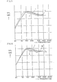
- Dashed curves in Fig. 3 and Fig. 4 show the characteristics after feedback at points A and C. In both cases, only the amount of feedback a is adjusted so that the frequency characteristics after feedback at points A and C become of the some characteristic curves with each other.
- F denote sound pressures after feedback while H denotes sound pressure without MFB.
- Fig. 5 and Fig. 6 show amounts of feedback in the states of Fig. 3 and Fig. 4, respectively.
- I denotes sound pressure without MFB.
- J and K denote sound pressures with MFB. Shaded regions correspond to negative feedback, while the other regions correspond to positive feedback.
- the feedback upper limit frequencies are denoted by L and M, respectively.
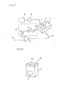
- FIG. 7 A block diagram for the actual measurement is shown in Fig. 7.
- An acceleration pick-up 3 is fixed on the center part of the diaphragm of a speaker 2.
- the frequency of input signal which is supplied to the speaker 2 from an input terminal 4 through a power amplifier 5 and a speaker code 6 is swept and the acceleration of the diaphragm at each frequency is detected by the pick-up 3.
- the output is drawn on a level recorder 9 through a pick-up cable 7 and a pick-up amplifier 8. If a switch S 1 is closed, MFB is applied through a microphone 10, the switch S 1 , a feedback amplifier 11, and a variable resistor R l .
- the amount of feedback ⁇ is varied by the variable resistor R 1 .
- Fig. 8 shows the first embodiment of this invention to which the above-mentioned principle is applied.
- An adapter 12 is placed in the vicinmy or a speaker.
- a feedback circuit composed of the microphone 10, switch S 1 , feedback amplifier 11 and variable resistor R 1 , etc., as shown in Fig. 7, is built in the adapter 12.
- an MFB speaker can be constituted simply.
- it is desirable that the setting position of the adapter 12 is in the vicinity of the speaker box 1 as near as possible, it is not always necessary to make it in intimate contact with the speaker box 1. Freedom of setting is extremely large.
- the amount of feedback should be set less than or equal to 0 dB at a frequency where the difference between the phases of the reproduced sound of speaker 2 and of the detected signal of microphone 10 becomes larger than or equal to 90°.
- a speaker for low-pitched tone 14 (hereinafter called as woofer) and a speaker for high-pitched tone 13 (hereinafter called as tweeter) are mounted on a buffle plate la of a speaker box.
- a microphone 10 is mounted in the vicinity of the diaphragm of woofer 14 on the buffle plate la of a speaker box 1.
- Fig. 10 shows the sound pressure-frequency characteristic actually measured by the apparatus of Fig. 9.
- N denotes measured data in the case where the microphone is disposed on the position of 1 cm on the sound radiation axis of woofer 14 while 0 denotes data in the case where the microphone is disposed at a position of 1 cm above the buffle plate la of the speaker box 1, distanced by 8 cm from the sound radiation axis of woofer 14 in a plane perpendicular to the axis.
- N and 0 have nearly a similar pattern. Namely, it is seen that not only the position with the characteristic N but also the position with the characteristic O is satisfactory as the detecting position of microphone to control the speaker.
- phase difference becomes less than or equal to 90° and a negative feedback results in if the distance between the speaker and the microphone 10 is less than or equal to a 1/4. wavelength at the feedback upper-limit frequency. Therefore, when.the microphone 10 and the speaker are separated by 8 cm, a negative feedback may be applied up to 1 KHz since the phase difference bcomes 90° at 1.06 KHz.
- a switch S 1 if the switch S 1 is closed, the microphone 10 detects the signal which is proportional to the reproduced sound pressure of woofer 14 and the detected signal is introduced to a feedback amplifier 11 through the switch S 1 . A prescribed quantity is fed back to the input of a power amplifier 5 and hence an MFB is applied.
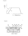
- Fig. 11 shows the sound pressure-frequency characteristic before and after feedback in the present embodiment.
- the abscissa is the frequency and the ordinate is the sound pressure.
- P denotes the sound pressure-frequency characteristic before feedback while Q denotes the sound pressure-frequency characteristic after feedback.
- the lowest resonance frequency can be decreased by the application of MFB and that the sound pressure characteristic is improved.
- the microphone may be disposed at any position on the buffle la, it is desirable that it is in'the vicinity of the speaker in view of the phase difference between the speaker and the microphone 10, which is not to exceed 90° at the feedback upper limit frequency and the detection sensitivity of the microphone.
- the front panel can be taken as the buffle plate of the speaker box. Therefore, in such a case, the microphone may be mounted on the front panel of the cabinet.
- a microphone for MFB may be mounted on the buffle plate of the speaker box so that the reproduced sound from the diaphragm and the bassreflex point is detected by this microphone to control the speaker. Then, a speaker apparatus of bassreflex type with a stable characteristic can be realized.
- the third embodiment of this invention is shown in Fig. 12 to Fig. 14.
- tweeter 13 and woofer 14 are built in a speaker box 1.
- a microphone 10 is provided near the center of an equalizer grille 15 for the tweeter.
- This microphone 10 detects both the reproduced sound of tweeter 13 and the reproduced sound of woofer 14 which are fed back to an inverting input of a power amplifier 17 through a feedback circuit 16 as shown in Fig. 13.
- Reference numeral 18 denotes a network which drives the tweeter 13 and the woofer 14.
- the microphone 10 detects sounds in the whole reproduction frequency range from low-pitched tone to high-pitched tone, the so-called acceleration feedback is applied to the tweeter 13 and the woofer 14. Distortions of tweeter 13 and woofer 14 are reduced by the amount of feedback. Especially, in the woofer 14, the lowest resonance frequency in the lower frequency range is lowered. This situation is shown in F ig. 14.
- the abscissa is the frequency and the ordinate is the sound pressure.
- Solid curve R denotes the characteristic before feedback while dashed curve S denotes the characteristic after feedback. It is apparent that the lowest resonance frequency in the lower frequency range is lowered.
- the stand or angle arm resonates by receiving the radiation sound of the speaker, reflects it and causes irregular disturbance on the frequency characteristic. Furthermore, wavelength becomes short in the higher frequency range and yet since the distance between the tweeter 13 and the microphone 10 becomes large, the phase rotates and feedback is not applicable.
- the sound velocity is 340 m/s.
- the phase exceeds 90° above 1 KHz corresponding to 1/4 wavelength and positive feedback appears. The appearance of the negative feedback is limited below 1 KHz.
- the microphone 10 when the microphone 10 is provided at the acoustic center on the axis of tweeter 13 ensuring a small phase lag for the high-pitched tone, feedback becomes, in principle, possible as far as the reproduction limiting high frequency of tweeter 13. Furthermore, the tweeter 13 is usually provided with the equalizer grille 15 in order to make flat the frequency characteristic at the receiving point. If a small type microphone 10 is provided at the center of this equalizer grille 15 and the form of equalizer is selected to make flat the frequency characteristic at the receiving point including the microphone 10, the disadvantages of an angle arm, etc. which is placed in front of the woofer 14 can be avoided. In this case, the microphone need not always be mounted on the equalizer 15 of tweeter 13.
- the microphone 10 may be fixed on a stand or alternatively it may be fixed in a hole which is provided in the center of the diaphragm of tweeter 13. In any case, if the microphone is set in the vicinity of the acoustic center of tweeter 13, feedback can be applied from high-pitched to low-pitched tones.
- the microphone 10 can detect correctly the reproduced sound pressure of woofer 14 is apparent from the following. Namely, the directivity of the speaker at low-pitched tones is non-directional; the difference being of the order of 1 - 3 dB between on the sound radiation axis and near the speaker; since the wavelength is long, the sound pressure is equal in a wide range of direction; the phase rotation is very small or of a negligible order. If a non directional microphone is used as the microphone 10, the microphone need not always be directed toward the direction of woofer 14.
- the microphone 10 it is naturally desirable, in this case, to place the microphone 10 as near as possible to the acoustic center of woofer 14 in view of phase and sensitivity characteristics. It is preferable that the tweeter and the woofer are located close to each other, if the directional characteristic of the speaker system at the receiving point is taken into account.
- Fig. 15 shows the fourth embodiment of this invention, where such a problem is solved.
- 10 denotes a microphone for MFB, 19 a diaphragm for high-pitched tone, 20, 21, 22'edges, 23, 24 frames, 25 a diaphragm for low-pitched tone, 26, 27 top plates, 28, 29 magnets, 30, 31 yokes, 32 a pipe, 33, 34 voice coil bobbins, and 35 a damper.
- the relation of connecting the circuit for driving the speaker apparatus of Fig. 12 is the same as that shown in Fig. 13.
- the tweeter 13 of Fig. 13 is a coanial type tweeter and the woofer 14 is a coaxial type woofer.
- the signal is divided into high-pitched tone and low-pitched tone to drive the tweeter 13 and the woofer 14.
- the microphone 10 provided in the center hole detects the reproduced sound of the tweeter 13 and the woofer 14 and feeds it back'to a power amplifier 17 through a feedback circuit 16.
- the MFB theory it is well known from the MFB theory that as the microphone 10 detects the signal proportional to the acceleration of the speaker 13, 14 the acceleration feedback is applied, that the lower reproduction limit frequency of woofer 14 is lowered; and that the distortion is reduced by the amount of feedback.
- the reproduction-sound detecting sensitivities of tweeter 13 and woofer 14 are nearly equal.
- a sensitivity correcting equalizer that has been conventionally necessary for the case when the woofer 14 is distanced from the microphone 10 is not necessary.
- the speaker is of coaxial type, the inter-modulation distortion that has been the.conventional problem is mitigated by the amount of feedback.
- the harmonic distortion is also improved.
- the tweeter 13 and the woofer 14 are disposed concentric, the directivity characteristic of the speaker is improved in comparison with the conventional multi-unit type. The low frequency region-is expanded by the acceleration feedback. Then, a unique speaker with a high performance can be provided.
- the microphone is placed in a hole provided in the diaphragm of the speaker for high-pitched tone, the diaphragm need not always be perforated.
- the microphone is placed in the vicinity of the diaphragm near the sound radiation axis of the diaphragm for high-pitched tone under the condition that the phase of the reproduced sound does not rotate much, and fixed by an acoustic equalizer or a grille of the tweeter 13.
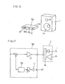
- Fig. 16 and Fig. 17 show the fifth embodiment of this invention, where a microphone 10 for MFB is mounted on the panel 36a of an audio apparatus 36.
- 37 is a switch and 38 is a variable resistor for feedback control.
- the output terminal of this audio apparatus 36 is connected with an input terminal of a speaker box 1, as shown in Fig. 17.
- the audio apparatus 36 is placed in the vicinity of the speakers 13, 14. Reproduced sound of the speakers 13, 14 generated from the speaker box 1 is detected by the microphone 10 and fed back to the speakers 13, 14 through the audio apparatus 36.
- the amount of feedback should be set less than or equal to 1 if the phases of the reproduced sound of speakers 13, 14 and the detected sound of the microphone 10 is more than or aqual to 90°. If we take the sound velocity as 340 m/s and apply the negative feedback up to 300 Hz, the distance between the microphone 10 and the speakers 13, 14 should be set within about 28 cm by considering the wavelength.
- Fig. 17 is a block diagram of the audio apparatus 36, where the reproduced sound of the speaker 13, 14 is detected by the microphone as an acoustic pressure and applied to an inverting input of the power amplifier 17 through the feedback amplifier 11 and the phase correction circuit 39.
- the variable resistor R 1 for feedback control varies the amount of feedback. If we assume that the gains of the power amplifier 17 and the feedback amplifier 11 are A and ⁇ respectively, the lowest resonance frequencies of the speakers 13, 14 after feedback decrease in proportion to the inverse of the amount of feedback 1 + AS.
- the audio apparatus 36 provided with a microphone 10 for MFB and a feedback circuit is mounted in the vicinity of the speaker box 1 without reconstructing the speaker.
- MFB can be applied to the speakers 13, 14.
- the frequency characteristic after feedback becomes smooth in proportion to the amount of feedback. Distortions due to bending motion of the diaphragm of speaker and the inhere sound due to the resonance of cabinet which cannot be detected by the vibration detector can be detected. Therefore, there is a merit of a decrease in distortion.
- Fig. 16 and Fig. 17 shows the provision of an MFB microphone in the audio apparatus 36 with the built-in power amplifier 17, it is needless to say that the MFB microphone can be disposed on an arbitrary position of an audio apparatus provided with a preamplifier, an equalizer, a tuner, a tape recorder and a record player other than the power amplifier.
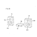
- a microphone 10 for MFB is provided on the surface of an audio apparatus 36 which is the same as the audio apparatus 36 as shown in Fig. 16.
- Low-pitched tones reproduced by woofers 14L, 14R in the left and right speaker boxes 1L, 1R are detected by the microphone 7 on the audio apparatus 36 provided in the center of the speaker boxes 1L, 1R and fed back to the power amplifier.
- the reproduced sounds of woofers 14L, 14R are detected by the microphone 10.
- a low-pitched tone signal is derived from a low pass filter 4'0 through a feedback circuit 16. This is fed back to the inverting input of each amplifier (subtractor) 41L, 41R.
- Equalizers 42L, 42R filter the wave at the feedback upper limit frequency of MFB.
- the phase differences between the reproduced sounds of woofers 14L, 14R and the detected signal of the microphone 10 become 90° when the distances from the microphone 10 to woofers 14L, 14R are 1/4 wavelength or 85 cm. Namely, the amount of feedback becomes zero.
- the detection sensitivity of the microphone 10 decreases and the amount of feedback becomes less than or equal to 1. Therefore, even if the phase rotates more than 90°, neither positive feedback nor oscillation occurs.
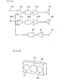
- Fig. 20 shows a modification of Fig. 18.
- the invention is applied to a cassette tape recorder combined with a radio and a compact stereo, etc. where left and right speakers 2L, 2R are accommodated in a common cabinet 45.
- the microphone 10 for MFB is provided in the center part of the cabinet 45. Furthermore, since the distance between the microphone 10 and the speakers 2L, 2R are fixed, there is a merit that the characteristics are guaranteed simply.
- Embodiments of Fig. 18 to Fig. 20 have an extremely large utility, since a plurality of microphones are not required to apply MFB in an audio apparatus having a plurality of reproduction systems; MFB is constituted with only one microphone; especially when the low pass filter 40 of Fig. 19 is limited below 100 Hz, the sound image of stereo reproduction is defined or localized without any substantial damage; in the case of MFB by the acceleration feedback, a reduction of the lowest resonance frequency of speakers can be attained cheaply. Furthermores, the embodiments have an extremely large effect of reducing the lowest resonance frequency in cassette tape recorders attached with a radio with a small type cabinet, etc.
- the essential of this invention lies in that a microphone is disposed in a plane which is substantially perpendicular to the radiation direction of the speaker and contains substantially the acoustic center of the speaker and that the output of the microphone is fed back to a power amplifier in a frequency range lower than a frequency at which the distance between the speaker and the microphone is equal to 1/4 wavelength.
- the output signal of the microphone is directly fed back to the power amplifier, it is needless to say that the lowest resonance frequency and its sharpness Q can be varied by the feedback through an integration circuit, by the velocity feedback or by the amplitude feedback.
- a speaker apparatus wherein the detection by a microphone or an MFB detecting element gives no influence on the reproduction of sound; limitation of design is little; design or external appearance is excellent; the feedback upper limit frequency is high; and the influence of Doppler distortion is small.
Landscapes
- Physics & Mathematics (AREA)
- Engineering & Computer Science (AREA)
- Acoustics & Sound (AREA)
- Signal Processing (AREA)
- Circuit For Audible Band Transducer (AREA)
Abstract
Applications Claiming Priority (6)
| Application Number | Priority Date | Filing Date | Title |
|---|---|---|---|
| JP57180705A JPS5970098A (ja) | 1982-10-14 | 1982-10-14 | スピ−カ装置 |
| JP180705/82 | 1982-10-14 | ||
| JP201353/82 | 1982-11-15 | ||
| JP57201341A JPS5990489A (ja) | 1982-11-15 | 1982-11-15 | スピ−カ |
| JP57201353A JPS5990496A (ja) | 1982-11-15 | 1982-11-15 | スピ−カ装置 |
| JP201341/82 | 1982-11-15 |
Publications (3)
| Publication Number | Publication Date |
|---|---|
| EP0122290A1 true EP0122290A1 (fr) | 1984-10-24 |
| EP0122290A4 EP0122290A4 (fr) | 1986-10-02 |
| EP0122290B1 EP0122290B1 (fr) | 1991-04-03 |
Family
ID=27324890
Family Applications (1)
| Application Number | Title | Priority Date | Filing Date |
|---|---|---|---|
| EP83903209A Expired EP0122290B1 (fr) | 1982-10-14 | 1983-10-13 | Haut-parleur |
Country Status (4)
| Country | Link |
|---|---|
| US (1) | US4592088A (fr) |
| EP (1) | EP0122290B1 (fr) |
| DE (1) | DE3382241D1 (fr) |
| WO (1) | WO1984001682A1 (fr) |
Cited By (2)
| Publication number | Priority date | Publication date | Assignee | Title |
|---|---|---|---|---|
| EP0208389A3 (en) * | 1985-06-27 | 1988-03-16 | Bose Corporation | Headphone apparatus |
| GB2196815A (en) * | 1986-09-25 | 1988-05-05 | David Robin Birt | Motional feedback system for loudspeakers |
Families Citing this family (47)
| Publication number | Priority date | Publication date | Assignee | Title |
|---|---|---|---|---|
| DE3429147C2 (de) * | 1984-08-08 | 1987-04-02 | Friedrich 6650 Homburg Müller | Anordnung zur akustischen Gegenkopplung von Lautsprechern |
| US5361381A (en) * | 1990-10-23 | 1994-11-01 | Bose Corporation | Dynamic equalizing of powered loudspeaker systems |
| DE19507850A1 (de) * | 1995-03-07 | 1996-09-12 | Juergen Hasenmaier | Abnahme-Verstärkersystem für eine Beschallungsanlage |
| DE19746645C1 (de) * | 1997-10-22 | 1999-05-20 | Fraunhofer Ges Forschung | Adaptiver akustischer Monitor |
| US6434240B1 (en) * | 1997-12-19 | 2002-08-13 | Charles J. Kulas | Sound isolation cabinet using two sound sources to generate complimentary sound waves |
| US6792120B1 (en) | 1999-02-25 | 2004-09-14 | Jonathan M. Szenics | Audio signal enhancement and amplification system |
| JP2001157293A (ja) * | 1999-12-01 | 2001-06-08 | Matsushita Electric Ind Co Ltd | スピーカ装置 |
| US7031476B1 (en) | 2000-06-13 | 2006-04-18 | Sharp Laboratories Of America, Inc. | Method and apparatus for intelligent speaker |
| US20040101153A1 (en) * | 2001-05-08 | 2004-05-27 | Oleg Grudin | Gas flow sensor, speaker system and microphone, utilizing measurement absolute of time-variations in absolute pressure |
| CA2408045A1 (fr) * | 2001-10-16 | 2003-04-16 | Audio Products International Corp. | Haut-parleur a asservissement a grand deplacement |
| JP3823824B2 (ja) * | 2001-12-27 | 2006-09-20 | ヤマハ株式会社 | 電子楽音発生装置および信号処理特性調整方法 |
| JP3896967B2 (ja) * | 2003-01-10 | 2007-03-22 | 松下電器産業株式会社 | 圧電スピーカ |
| WO2004110095A1 (fr) * | 2003-06-05 | 2004-12-16 | Koninklijke Philips Electronics N.V. | Haut-parleur et microphone combines |
| US9084058B2 (en) | 2011-12-29 | 2015-07-14 | Sonos, Inc. | Sound field calibration using listener localization |
| US9706323B2 (en) | 2014-09-09 | 2017-07-11 | Sonos, Inc. | Playback device calibration |
| US9690539B2 (en) | 2012-06-28 | 2017-06-27 | Sonos, Inc. | Speaker calibration user interface |
| US9106192B2 (en) | 2012-06-28 | 2015-08-11 | Sonos, Inc. | System and method for device playback calibration |
| US9668049B2 (en) | 2012-06-28 | 2017-05-30 | Sonos, Inc. | Playback device calibration user interfaces |
| US9690271B2 (en) | 2012-06-28 | 2017-06-27 | Sonos, Inc. | Speaker calibration |
| US9219460B2 (en) | 2014-03-17 | 2015-12-22 | Sonos, Inc. | Audio settings based on environment |
| US8965033B2 (en) | 2012-08-31 | 2015-02-24 | Sonos, Inc. | Acoustic optimization |
| US9118985B2 (en) * | 2012-12-04 | 2015-08-25 | Bose Corporation | Communication of diagnostic information from satellite to host |
| US9264839B2 (en) | 2014-03-17 | 2016-02-16 | Sonos, Inc. | Playback device configuration based on proximity detection |
| US10127006B2 (en) | 2014-09-09 | 2018-11-13 | Sonos, Inc. | Facilitating calibration of an audio playback device |
| US9910634B2 (en) | 2014-09-09 | 2018-03-06 | Sonos, Inc. | Microphone calibration |
| US9891881B2 (en) | 2014-09-09 | 2018-02-13 | Sonos, Inc. | Audio processing algorithm database |
| US9952825B2 (en) | 2014-09-09 | 2018-04-24 | Sonos, Inc. | Audio processing algorithms |
| US9973851B2 (en) | 2014-12-01 | 2018-05-15 | Sonos, Inc. | Multi-channel playback of audio content |
| WO2016172593A1 (fr) | 2015-04-24 | 2016-10-27 | Sonos, Inc. | Interfaces utilisateur d'étalonnage de dispositif de lecture |
| US10664224B2 (en) | 2015-04-24 | 2020-05-26 | Sonos, Inc. | Speaker calibration user interface |
| US9538305B2 (en) | 2015-07-28 | 2017-01-03 | Sonos, Inc. | Calibration error conditions |
| WO2017049169A1 (fr) | 2015-09-17 | 2017-03-23 | Sonos, Inc. | Faciliter l'étalonnage d'un dispositif de lecture audio |
| US9693165B2 (en) | 2015-09-17 | 2017-06-27 | Sonos, Inc. | Validation of audio calibration using multi-dimensional motion check |
| US9743207B1 (en) | 2016-01-18 | 2017-08-22 | Sonos, Inc. | Calibration using multiple recording devices |
| US11106423B2 (en) | 2016-01-25 | 2021-08-31 | Sonos, Inc. | Evaluating calibration of a playback device |
| US10003899B2 (en) | 2016-01-25 | 2018-06-19 | Sonos, Inc. | Calibration with particular locations |
| US9864574B2 (en) | 2016-04-01 | 2018-01-09 | Sonos, Inc. | Playback device calibration based on representation spectral characteristics |
| US9860662B2 (en) | 2016-04-01 | 2018-01-02 | Sonos, Inc. | Updating playback device configuration information based on calibration data |
| US9763018B1 (en) | 2016-04-12 | 2017-09-12 | Sonos, Inc. | Calibration of audio playback devices |
| US9794710B1 (en) | 2016-07-15 | 2017-10-17 | Sonos, Inc. | Spatial audio correction |
| US9860670B1 (en) | 2016-07-15 | 2018-01-02 | Sonos, Inc. | Spectral correction using spatial calibration |
| US10372406B2 (en) | 2016-07-22 | 2019-08-06 | Sonos, Inc. | Calibration interface |
| US10459684B2 (en) | 2016-08-05 | 2019-10-29 | Sonos, Inc. | Calibration of a playback device based on an estimated frequency response |
| US10299061B1 (en) | 2018-08-28 | 2019-05-21 | Sonos, Inc. | Playback device calibration |
| US11206484B2 (en) | 2018-08-28 | 2021-12-21 | Sonos, Inc. | Passive speaker authentication |
| US10734965B1 (en) | 2019-08-12 | 2020-08-04 | Sonos, Inc. | Audio calibration of a portable playback device |
| EP4409571B1 (fr) | 2021-09-30 | 2025-03-26 | Sonos Inc. | Gestion de conflit pour processus de détection de mot d'activation |
Family Cites Families (14)
| Publication number | Priority date | Publication date | Assignee | Title |
|---|---|---|---|---|
| US2841648A (en) * | 1955-08-08 | 1958-07-01 | Electro Voice | Sound producing device |
| US3009991A (en) * | 1955-12-01 | 1961-11-21 | Bekey Ivan | Sound reproduction system |
| DE2141141A1 (de) * | 1971-08-12 | 1973-02-22 | Neumann Gmbh Georg | Schaltungsanordnung zur gegenkopplung eines lautsprechers |
| US3943564A (en) * | 1975-06-05 | 1976-03-09 | Superscope, Inc. | Stereophonic recording and playback apparatus |
| US4100380A (en) * | 1976-03-12 | 1978-07-11 | Federal Signal Corporation | Supervisory circuit for monitoring speaker coils |
| NL7609200A (en) * | 1976-08-19 | 1978-02-21 | Philips Nv | Amplifier and loudspeaker circuit - has feedback loop including phase shifting correction network operating below speaker resonance point |
| DE2725346C3 (de) * | 1977-06-04 | 1981-05-14 | Josef Wilhelm 8725 Arnstein Manger | Lautsprecher |
| JPS5814795B2 (ja) * | 1977-11-01 | 1983-03-22 | 日本ビクター株式会社 | マルチウエイスピ−カの駆動回路方式 |
| JPS5539460A (en) * | 1978-09-14 | 1980-03-19 | Matsushita Electric Ind Co Ltd | Headphone |
| JPS6025194Y2 (ja) * | 1978-11-13 | 1985-07-29 | 株式会社東芝 | アコ−ステイツクフイ−ドバツクシステム |
| JPS55112097A (en) * | 1979-02-21 | 1980-08-29 | Sony Corp | Acoustic system |
| US4276443A (en) * | 1979-08-17 | 1981-06-30 | Meyers Stanley T | Sound reproducing system utilizing motional feedback and velocity-frequency equalization |
| NL8001592A (nl) * | 1980-03-18 | 1981-10-16 | Philips Nv | Mfb systeem met een overnamenetwerk. |
| JPS57188198A (en) * | 1981-05-15 | 1982-11-19 | Sanyo Electric Co Ltd | Motional feedback speaker circuit |
-
1983
- 1983-10-13 US US06/621,917 patent/US4592088A/en not_active Expired - Fee Related
- 1983-10-13 WO PCT/JP1983/000345 patent/WO1984001682A1/fr not_active Ceased
- 1983-10-13 DE DE8383903209T patent/DE3382241D1/de not_active Expired - Lifetime
- 1983-10-13 EP EP83903209A patent/EP0122290B1/fr not_active Expired
Cited By (2)
| Publication number | Priority date | Publication date | Assignee | Title |
|---|---|---|---|---|
| EP0208389A3 (en) * | 1985-06-27 | 1988-03-16 | Bose Corporation | Headphone apparatus |
| GB2196815A (en) * | 1986-09-25 | 1988-05-05 | David Robin Birt | Motional feedback system for loudspeakers |
Also Published As
| Publication number | Publication date |
|---|---|
| EP0122290B1 (fr) | 1991-04-03 |
| DE3382241D1 (de) | 1991-05-08 |
| WO1984001682A1 (fr) | 1984-04-26 |
| US4592088A (en) | 1986-05-27 |
| EP0122290A4 (fr) | 1986-10-02 |
Similar Documents
| Publication | Publication Date | Title |
|---|---|---|
| EP0122290B1 (fr) | Haut-parleur | |
| US4051919A (en) | High fidelity speaker enclosure | |
| KR890000105B1 (ko) | 스피커 장치 | |
| US5815589A (en) | Push-pull transmission line loudspeaker | |
| US4610024A (en) | Audio apparatus | |
| US4276443A (en) | Sound reproducing system utilizing motional feedback and velocity-frequency equalization | |
| US4596034A (en) | Sound reproduction system and method | |
| GB2074427A (en) | Acoustic apparatus | |
| EP0113370A1 (fr) | Systemes de haut-parleurs s'adaptant a l'environnement | |
| US4100371A (en) | Loudspeaker system with phase difference compensation | |
| US4154979A (en) | Woofer efficiency | |
| JP3068635B2 (ja) | スピーカ装置 | |
| CA1120580A (fr) | Haut-parleur comportant un transducteur a bobine mobile pour circuit de retour | |
| CA2091324C (fr) | Enceinte acoustique | |
| US6031921A (en) | Loudspeaker unit | |
| JPH02218295A (ja) | オーディオ出力装置 | |
| GB2037130A (en) | Single source stereo sound | |
| JP3900676B2 (ja) | オーディオ装置の聴取位置自動設定装置 | |
| US20050286727A1 (en) | Apparatus for expanding sound image upward | |
| JPH01151898A (ja) | 低音スピーカボツクス | |
| JPH06311582A (ja) | スピーカ装置 | |
| JPS59183581A (ja) | スピ−カシステム | |
| CA1110176A (fr) | Enceinte a woofer egalise | |
| JPH05199584A (ja) | フットモニタースピーカシステム | |
| JP3018597B2 (ja) | マイクロホン装置 |
Legal Events
| Date | Code | Title | Description |
|---|---|---|---|
| PUAI | Public reference made under article 153(3) epc to a published international application that has entered the european phase |
Free format text: ORIGINAL CODE: 0009012 |
|
| 17P | Request for examination filed |
Effective date: 19840620 |
|
| AK | Designated contracting states |
Designated state(s): DE FR GB |
|
| A4 | Supplementary search report drawn up and despatched |
Effective date: 19861002 |
|
| 17Q | First examination report despatched |
Effective date: 19881108 |
|
| GRAA | (expected) grant |
Free format text: ORIGINAL CODE: 0009210 |
|
| AK | Designated contracting states |
Kind code of ref document: B1 Designated state(s): DE FR GB |
|
| REF | Corresponds to: |
Ref document number: 3382241 Country of ref document: DE Date of ref document: 19910508 |
|
| ET | Fr: translation filed | ||
| PLBE | No opposition filed within time limit |
Free format text: ORIGINAL CODE: 0009261 |
|
| STAA | Information on the status of an ep patent application or granted ep patent |
Free format text: STATUS: NO OPPOSITION FILED WITHIN TIME LIMIT |
|
| 26N | No opposition filed | ||
| PGFP | Annual fee paid to national office [announced via postgrant information from national office to epo] |
Ref country code: GB Payment date: 19941004 Year of fee payment: 12 |
|
| PGFP | Annual fee paid to national office [announced via postgrant information from national office to epo] |
Ref country code: DE Payment date: 19941010 Year of fee payment: 12 |
|
| PGFP | Annual fee paid to national office [announced via postgrant information from national office to epo] |
Ref country code: FR Payment date: 19941011 Year of fee payment: 12 |
|
| PG25 | Lapsed in a contracting state [announced via postgrant information from national office to epo] |
Ref country code: GB Effective date: 19951013 |
|
| GBPC | Gb: european patent ceased through non-payment of renewal fee |
Effective date: 19951013 |
|
| PG25 | Lapsed in a contracting state [announced via postgrant information from national office to epo] |
Ref country code: FR Effective date: 19960628 |
|
| PG25 | Lapsed in a contracting state [announced via postgrant information from national office to epo] |
Ref country code: DE Effective date: 19960702 |
|
| REG | Reference to a national code |
Ref country code: FR Ref legal event code: ST |